objects are stored in a directed a-cyclic graph called the scene ... Figure 2: A Scene and its associated Scene Graph. .... the Cosmo3D [10] scene graph API.
VRIC, Virtual Reality International Conference, Lava Virtual 2001, May 16-18
Integration of Constraints into a VR Environment G. Smith and W. Stuerzlinger Dept. of Computer Science, York University 4700 Keele St., Toronto, Ontario, Canada M3J 1P3
Keywords: interactive 3D VR environments, 3D scene construction, semantic constraints Abstract: Interactive Virtual Reality applications are in general complex and non-intuitive. One fundamental problem is that manipulation of 3D objects is very difficult for non-experienced users. We describe a constraint based 3D scene construction system that exploits human intuitions to restrict object placement and interactions. In particular, we focus on the constraints themselves by describing how they are defined, and how they are used within a scene. Several different types of constraints are discussed, including virtual constraints, which decouple the constraint areas from the geometry of an object, and negative constraints, which restrict object placements within certain volumes of space. Furthermore, we discuss techniques that can be used to automatically generate constraints for most geometric objects, which makes incorporating new objects into the system much easier. Finally, we argue that the presented constraint techniques can be incorporated into existing Virtual Reality systems to make interactions easier.
1. Introduction The field of computer graphics has advanced considerably in the last several years. Computer images and animations are achieving realism which was previously impossible. Applications such as physical simulations, architectural walk-through, and other Virtual Reality (VR) systems require semi-realistic three-dimensional (3D) scenes composed of many objects. The objects in these scenes are generally detailed geometric models, and many techniques exist for creating them. Many applications are readily available in the areas of 3D modeling and scene construction/manipulation, but in general, these products are difficult to use and require many hours of training. For example, products such as Maya (Alias|wavefront) and 3D Studio Max (Discreet) have dozens of menus, modes and widgets for scene creation and manipulation, which can be very intimidating for an untrained user. Our efforts address these difficulties. Creating a 3D scene from scratch, or modifying an existing 3D scene is in general a very complex task. To simplify the problem, we choose to focus on the creation and modification of 3D scenes based on a library of existing objects. Here the challenge is to enable the user to easily add objects and to quickly position them in the environment. In general, positioning an object in a 3D scene is difficult as six independent variables must be controlled, three for positioning and three for orientation.
Our observations of humans rearranging furniture and planning environments indicate that humans do not think about scene manipulation as a problem with six degrees of freedom. The rationale is that most real objects are not placed arbitrarily in space, but are constrained by physics (e.g. gravity) and/or human conventions (ceiling lamps are almost never placed permanently onto the floor or onto chairs). This leads us to believe that an interface that exposes the full six degrees of freedom to the user makes it harder for the average person to interact with virtual environments. Many real objects have a maximum of three degrees of freedom in practice – e.g. all objects resting on a plane. In addition, many objects are often placed against walls or other objects, thus further reducing the available degrees of freedom. This implies that a two-dimensional (2D) input device such as a mouse is sufficient to manipulate objects in a virtual environment. In our system, information about how an object interacts with the physical world assists the user in placing and manipulating objects in virtual environments. Each object in a scene is given a set of rules, called constraints, which must be followed when the object is being manipulated. For example, a photocopier must stand on the floor at all times. When a user interacts with the photocopier by translating or rotating it in the scene, it never leaves the floor. This concept of constraints makes manipulating objects in 3D much simpler.
VRIC, Virtual Reality International Conference, Lava Virtual 2001, May 16-18
1.1
Previous Work
For 2D object manipulation various forms of constraint systems have been introduced. For recent work on interactive constraint satisfaction and references to previous work see [4][19]. Previous work on 3D object manipulation can be classified into two categories: those that use 2D and those that use 3D input devices. The simplest solution for a 2D input device is to decompose the manipulation task into positioning and orientation. Unfortunately, there is no intuitive mapping of these tasks with three degrees of freedom each to a mouse with three buttons. Bier introduced ‘Snap-Dragging’ [1] to simplify the creation of line drawings in a 2D interactive graphics program. The mouse cursor snaps to points and curves using a gravity function. Bier subsequently applied these ideas to placing and orienting objects in a 3D environment [2]. The main features of this system are a general-purpose gravity function, 3D alignment objects, and smooth motion affine transformations of objects. Gleicher [9] built on this work and introduced a method that can deal even with non-linear constraints. For 3D scene construction Bukowski and Sequin [7] employ a combination of pseudo-physical and goal-oriented properties called ‘Object Associations’ to position objects in a 3D scene with 2D devices (mouse and monitor). Although intuitive, their approach has a few drawbacks. First, associations apply only to the object currently being moved and are not maintained after the current manipulation. In addition, when an object is selected for relocation, a local search for associated objects is performed, which can result in lag between the motion of the selected object and the motion of its associated objects. Goesele and Stuerzlinger [8] built upon the ideas of Object Associations. Each scene object is given predefined offer and binding areas. These areas are used to define constraining surfaces between objects. Collision detection is used to prevent objects from passing though each other. Drawbacks of this approach include the following: Once a constraint has been satisfied, there are no means to re-constrain an object to another surface or to un-constrain it. Furthermore, the constraint satisfaction search is global, in that an object will be moved across the entire scene to satisfy a constraint, This has often-undesirable effects for the user, especially because constraints cannot be undone. A number of authors have investigated the performance of object manipulation with 3D input devices, such as a space-ball or a six degree-offreedom tracker. Such devices enable direct interaction with a 3D scene. In combination with
devices that generate a 3D view, such systems can simulate Virtual Reality (VR). One of the first researchers to use 3D devices to manipulate a 3D scene was Bolt in 1980 [3]. Subsequently many other researchers studied the creation and manipulation of 3D environments in VR (see e.g. [12][16]). Most of these systems provide collision detection. Very few utilize constraints for object manipulation and even these support only the simplest geometric constraints (e.g. on-plane). Closest to the work discussed here is the ‘SmartScene’ system by Multigen [18]. This VR system uses tracked pinch-gloves as interaction devices. For some tasks, object manipulation is facilitated with pre-defined object behaviors. These behaviors can express semantic properties of objects. More recently Bowman et al. [5], Mine et al. [12], and Pierce et al. [13] proposed different 3D manipulation methods that can be applied in a variety of settings. Poupyrev et al. recently also addressed the problem of 3D rotation [15]. For a more complete overview over previous work in this area, we refer the reader to [6].
1.2
Motivation
We wanted to provide a simple way for objects to constrain to each other without using a full constraint solver. Our initial hypothesis was that our virtual constraints would provide the basic functionality of a full constraint solver, but at a fraction of the computing cost, and without some of the problems inherent to constraint solving systems.
2. The MIVE System The MIVE (Multi-user Intuitive Virtual Environment) system extends the work done in [8] by improving the way existing constraints behave, and adding new useful constraints. This paper discusses only the interaction of a single user. Three of the main constraint ideas used in MIVE are virtual constraints, constraint semantics, and negative constraints.
2.1
Virtual Constraints
2.1.1 Design Decisions Our first thought when designing the MIVE constraint system was to use the geometry of objects to define constraints. Some object relationships are clearly based on geometry, such as the relationship between a tabletop and a book. One face of the book will rest on the top face of the table. However, there are some relationships that are more functional than physical.
VRIC, Virtual Reality International Conference, Lava Virtual 2001, May 16-18 For example, a chair is most commonly positioned in front of a desk or table, or beside other chairs in a row. These relationships are not based on the physical geometry of the chair. Instead they are based on our understanding of how chairs interact with other objects. Furthermore, basing the constraints on object geometry has many technical problems. Polygons making up the surface of an object may be slightly non-planar, which would cause difficulty when trying to constrain objects together. Also, since the polygons of an object are usually segmented, there may be slight gaps between them, or overlapping may occur. Rather than trying to fix the geometry of objects in our system, we chose to separate the constraints from the object geometry entirely. This manner is less restricted, and affords much more flexibility under a wide variety of situations. Another decision we had to make concerns where to store the constraints for an object. We wanted to support multiple file formats for object geometry, so that finding objects to import into our system would be easier. We decided to define constraints for an object in a file separate from that that defines the object geometry (same filename, different extension). 2.1.2 Implementation Each object in a scene is given predefined constraint areas. A constraint area is defined as a convex polygon, and an orientation vector. Each constraint area of an object can be one of two types, an offer area, or a binding area. Offer areas are used to define locations on an object where other objects are allowed to reside. For example, a table would have an offer area over its top surface so that the user can place objects on top of the table. Binding areas define locations on an object where this object can constrain to an offer area. For example, a chair would have a binding area below its base, so that it could be positioned on the offer area of the floor of a room. When a binding area constrains itself to an offer area, we say that binding area has been “satisfied”. Binding areas are allowed to be one of two types, hard or soft. Hard binding areas define constraints that must always be satisfied in the scene. For example, in figure 1, the bottoms of both the table and chair have a hard binding area on their base, which forces them to always lie on the floor. These constraints can never be broken. Alternately, a soft constraint can be defined for an object that is allowed to remain unsatisfied by an offer area. Such an area exists on the front of the chair in figure 1.
We call these two constraint types (offer and binding) Virtual Constraints because the areas are not limited by the geometry of the object. We can, for example, place an offer area that floats underneath a table, which can be used for constraining the front of a chair. Figure 1 illustrates a simple scene containing a table and chair. The virtual constraints under each side of the table have been highlighted. The front of the chair can be constrained to either of these areas.
Figure 1: Virtual Constraint under a table
2.2
Constraint Semantics
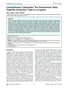
2.2.1 Design Decisions In practice, human placement of objects displays natural characteristics. For example, when placing a chair in a room, a person will never try to place it so that the base of the chair is on the wall. Most real objects are not placed arbitrarily in space, human conventions are usually followed. This leads us to believe that restricting object placement makes interactions more intuitive. So, in addition to using constraints, we introduce semantics to the constraint process to further restrict object placement/movement. 2.2.2 Implementation The current constraint relationships between objects are stored in a directed a-cyclic graph called the scene graph. Figure 2 depicts a simple scene, and it’s associated scene graph. When an object is moved in the scene, all of its descendants in the scene graph move with it.
VRIC, Virtual Reality International Conference, Lava Virtual 2001, May 16-18 A labeled constraint hierarchy is used to add semantics to the constraint process. The hierarchy is a tree structure, and defines the behavior of the constraint and offer areas. Every constraint area is associated with a label from the hierarchy. The label of a binding area defines what offer areas this binding area is allowed to attach to. A binding area constrains only to offer areas whose label is equal to or is an ancestor in the constraint hierarchy tree. This method is used to make object manipulations more intuitive.
Figure 2: A Scene and its associated Scene Graph. Links describe constraint relations Notice that edges in the scene graph of Figure 2 correspond directly to satisfied constraints in the scene. The user can modify the scene graph structure by interacting with objects in the scene. Constraints can be broken and re-constrained in with ease by simply clicking on the desired object, and pulling away from the existing constraint to break it. This allows us to dynamically change the structure of the scene graph. Figure 3 shows the same scene as Figure 2 after the chair has been pulled away from the large table, and dragged under the smaller table.
Figure 4: Semantic Constraint tree A simplified version of the semantic constraint tree used in MIVE is shown in Figure 4. This tree is used to restrict object placements. For example, the phone in fig 2 has a binding area on it base, which has the OnWorkspace label associated with it, hence it can be constrained to any offer area with an OnWorkspace label, OnHorizontal label, or OnPlane label. The top of the table has an OnWorkspace label associated with its offer area, so the phone can constrain there. The phone cannot be placed on the floor, which has an OnFloor label associated with its offer area, because the label of the floor’s offer area is not an ancestor of OnWorkspace in the tree. Semantics are added in a similar manner to every binding and offer area.
2.3
Negative Constraints
2.3.1 Design Decisions In 3D modeling and scene construction, it is possible to imagine volumes of space where we may wish to prevent certain objects from residing. For example, in practice when designing a room, a person would not place “large” objects directly in front of a doorway. To deal with such volumes in space, MIVE introduces a new constraint type, which we call negative constraints.
Figure 3: Scene from Fig.2 after moving chair
2.3.2 Implementation Negative constraints are defined on a per object basis. The constraint volume itself is defined as the sweep of a convex polygon. A desk, for example,
VRIC, Virtual Reality International Conference, Lava Virtual 2001, May 16-18 could have negative constraint volumes defined for each of its drawers by using the front of the drawer as the convex polygon, the direction the drawer opens as the sweep direction, and the depth of the drawer as the sweep length. Every object has a flag that is set to be “movable” or “unmovable”. Movable objects are generally small objects, and are allowed to move through negative constraint volumes unhindered. Unmovable objects are not allowed into any negative constraint volumes. Intuitively, we can think of an easily movable chair blocking a filing cabinet being less of a problem than if a desk was blocking the same cabinet from opening. Also, in many situations negative constraint volumes may intersect in the scene. For example, in a kitchen, the cabinets on the wall that meet at a corner will have doors that may collide if opened simultaneously. To deal with such cases, negative constraint volumes are allowed to intersect in MIVE. Initial experience with negative constraints proved confusing. It was difficult to tell the exact dimensions of the constraint volumes, and interacting with them was difficult. So, to provide cognitive visual feedback to the user, negative constraint volumes light up red when violated. This turns out to be very helpful when performing interactions, and makes placing objects around negative constraint areas very intuitive.
Figure 5: Scenes with and without negative constraints enabled
3. Constraint Satisfaction 3.1.1 Design Decisions When interacting with objects in the scene, we need to decide how and when they should become constrained to each other. One possibility is to provide a full constraint solver to attempt to find constraints between objects. This solution is computationally expensive when there are a large number of objects. Also, this method has the undesirable effect of causing objects to move by themselves, which, we believe, makes interaction with the environment non-intuitive. Another possibility, as done in [8], is to perform a global search for objects to constrain to when an object is being moved. However, this has the undesirable effect of causing objects to jump large distances across a scene to satisfy a constraint. We chose instead to perform a local search for constraints only for an object that is being moved by the user in the scene. Collision detection is used in our system to prevent interpenetration of objects in a scene. When objects become constrained to each other, due to mathematical inaccuracies and imprecise polygonal objects collisions may occur. For example, when a lamp is constrained to a desk, the base of the lamp sits against the top of the desk. If the lamp is translated along the surface of the desk, collisions
VRIC, Virtual Reality International Conference, Lava Virtual 2001, May 16-18 may occur between the base of the lamp, and the top of the desk. Simply disabling collision detection between objects that are constrained to each other may not be enough, because we may want certain parts of the objects to continue to collide. Figure 6 shows a lamp that has been constrained to a desk with the constraints disabled.
Figure 6: Collision of constrained objects One solution is to only disable collisions between polygons that fall completely within a bounding box of the constraint areas of the two objects. This allows us to disregard collisions along the constraint surfaces, while still checking collisions between other parts of the objects. This solution works well in practice. 3.1.2 Implementation For our constraint system, binding and offer areas both have a polygon and vector, which represent their effective areas and orientation. A binding area is satisfied by an offer area by aligning their orientation vectors and by translating the binding polygon so that it lies within the offer polygon (excluding the offer polygon edges). If after rotation and translation the binding polygon is not completely enclosed by the offer polygon, then the binding area is not constrained to the offer area. If the binding polygon does lie completely within the offer polygon, then the objects are checked for any geometric collisions. Since only one object is moving in the scene, collisions need only be checked between that moving object, and the rest of the objects in the scene. If no collisions are found, then the constraint was successful. In addition, a binding area cannot be bound to an offer area of the same object: an object cannot be constrained to itself. In Borning’s [4] terms, our
system implements locally-predicate-better constraints. To constrain an object, we attempt to satisfy all of its binding areas. For each binding area of an object, we search through the scene to find potential satisfying offer areas. Semantics restrict the offer areas that a binding area is allowed to constrain to. To prevent objects from jumping large distances to satisfy constraints, we only consider constraining an object to offer areas that are close to the object being constrained. Closeness is relative to object size, therefore we consider only objects that are within a sphere with a radius that is twice the radius of the sphere bound of the object. Using this heuristic, constraints remain unsatisfied until an object is moved close to a valid offer area. It also ensures that objects are always locally constrained. For each binding area, if there are multiple satisfying offer areas, the closest satisfying offer area found is chosen. The object is moved to connect the binding and offer areas. The bound object then becomes a child of the offering object in the scene graph, and the search is repeated for the next binding area. Once an object is constrained, its motion is restricted such that the binding areas of the object always remain in contact with the associated offer areas. This essentially removes degrees of freedom from object manipulations. When one object becomes constrained to another, it is placed as a child of the other object in the scene graph. When an object is moved, all descendants of that object in the scene graph move with it. So, constraining objects has the effect of uni-directional grouping. Constraints can be broken with ease by simply pulling an object away from its associated offer area. A constraint can only be broken if it is a soft constraint, and it has at least one other constraint that will remain satisfied. Objects are not allowed to have no satisfied constraints.
4. Constraint Generation We wished to be able to easily import a large number of objects into our system while avoiding the tedious task of defining constraints for these objects manually. Observations of object libraries showed that the orientation and size of objects are usually consistent across a library. Object constraints are stored in a text file that resides next to the file specifying the object geometry. This allows us to support multiple geometry file formats easily. In many cases, the offer and binding areas of an object fall precisely on faces of the bounding box of the object. For example, the tables in figure 2 have a binding area underneath (bottom of the
VRIC, Virtual Reality International Conference, Lava Virtual 2001, May 16-18 bounding box) that constrains to the floor, and an offer area on the workspace (top of the bounding box) so that objects may be placed on their surfaces. In fact, many other cases arise where the constraints of an object are just faces of the bounding box, which makes automatic generation of constraints possible for some objects. In other objects, we can exploit object geometry to further define constraints automatically. For example, in a bookcase, we can look for any polygons that have a normal pointing upward (i.e. the shelves), and place an offer area so that books may be constrained there. Automatic generation may not be possible in some cases, so a program was developed which allows a user to open a file specifying an objects geometry, and visually click points to make up an offer or binding polygon. This visual method of defining constraints is very simple and intuitive in practice, but may be tedious if many objects must have their constraints defined manually. Finally, since the constraints for an object are stored in a text file, we can manually open this file and specify any constraints we like. This method of defining constraints is rarely needed.
5. The MIVE Interface
object selection window, and clicking on the desired location to add it in the scene window. Drag & Drop is supported as well. To facilitate selection of small objects all objects are scaled logarithmically. The upper left-hand corner of the window contains buttons for performing tasks such as loading or saving the scene, deleting an object, undoing the previous operation, or quitting the program. There is also a radio button, which can be used to switch between interaction and navigation mode. This functionality was disabled for the tests in this publication. The MIVE system is implemented in C++ and runs on an SGI Onyx2 running IRIX 6.5. It is based on the Cosmo3D [10] scene graph API.
5.1
Interaction
The interface for MIVE was designed to be as simple and uncluttered as possible. All interactions between the participant and the program are done using a 3-button mouse. When constraints are enabled in MIVE, only two of the three buttons are needed. The left mouse button is used to translate objects by clicking and dragging them to the desired new location. The middle mouse button is used to rotate the objects. The third mouse button is currently unused.
6. Conclusion
Figure 7: The MIVE interface The MIVE interface consists of three windows: the scene window, the object selection window, and the button window. The scene window sits on the right hand side of the screen. The participant directly interacts with objects in the scene window by clicking and dragging them. The lower left-hand corner shows the object selection window. Objects are positioned on an invisible cylinder, which is rotated by clicking any mouse button within the window and dragging left and right. Objects are added to the scene window by simply clicking on the desired object in the
In this publication we presented a system that allows users to easily manipulate a 3D scene with traditional 2D devices. The MIVE system is based on semantic constraints, which enable an intuitive mapping from 2D interactions to 3D manipulations. Phrased differently, the semantic constraints and associated manipulation techniques encapsulate the user’s expectations of how objects move in an environment. These techniques are very general, and could be easily incorporated into existing interactive VR systems. The benefits of our interaction techniques become very apparent when one compares the simple MIVE user interface with the complex 3D user interface in commercial packages such as AutoCAD, Maya or 3DStudio Max that are also based on 2D input devices. We can only hypothesize at the outcome of a test comparing our system with e.g. Maya, but are confident that it is clearly easier to learn our user interface due to the reduced complexity. In fairness, we need to point out that these packages are also capable of object creation and the specification of animations, which our system does not currently address.
VRIC, Virtual Reality International Conference, Lava Virtual 2001, May 16-18
7. References 1.Bier, E.A., and Stone, M.C. Snap-dragging. SIGGRAPH 1986 proceedings, ACM Press, pp. 233-240.
16.Shaw, C., Green, M., THRED: A Two-Handed Design System, Multimedia Systems Journal,5(2),1997.
2.Bier, E.A. Snap dragging in three dimensions, SIGGRAPH 1990, pp. 193-204.
17.Shoemake, K., ARCBALL: A user interface for specifying three-dimensional orientation using a mouse, Graphics Interface, 1992, pp. 151-156.
3.Bolt, R., Put-that-there, SIGGRAPH ‘80, 262270.
18.SmartScene promotional material, Multigen (San Jose, CA), 1999.
4.Borning, A., Freeman, B., Ultraviolet: A Constraint Satisfaction Algorithm for Interactive Graphics, Constraints: An International Journal, 3, 1-26, 1998.
19.Zanden, B., Myers, B., Giuse, D., Szekely, Integrating Pointer Variables into One-Way Constraint Models, ACM Transactions on Computer-Human Interaction, 1(2), 161-213, 1994.
5.Bowman, D., Hodges, L. An evaluation of techniques for grabbing and manipulating remote objects in immersive virtual environments. Proceedings of ACM Symp. on Interactive 3D Graphics, 1997, pp. 35-38. 6.Bowman, D., Kruijff, E., LaViola, J., Mine, M., Poupyrev, I., 3D user interface design, ACM SIGGRAPH 2000, Course notes # 36, 2000. 7.Bukowski, R., and Sequin, C. Object associations. ACM Symp. Interactive 3D Graphics 1995, 131-138. 8.Goesele, M, Stuerzlinger, W. Semantic constraints for scene manipulation. Proc. Spring Conference in Computer Graphics 1999, pp. 140146. 9.Gleicher, M, A Graphics Toolkit Based on Differential Constraints. Proc. UIST 93, 109-120. 10.Eckel, G., Cosmo 3D programmers guide. Silicon Graphics Inc. 1998. 11.Mine, M., ISAAC: A Meta-CAD System for Virtual Environments. Computer-Aided Design, 29(8), 97. 12.Mine, M., Brooks, F., Sequin, C. Moving Objects in Space: Exploiting proprioception in virtual-environment interaction. SIGRAPH 1997, pp. 19-26. 13.Pierce, J., Forsberg, A., Conway, M., Hong, S., Zeleznik, R. et al., Image plane interaction techniques in 3D immersive environments. Proceedings of ACM Symp. on Interactive 3D Graphics. 1997. pp. 39-43. 14.Poupyrev, I., Weghorst, S., Billinghurst, M., Ichikawa, T., Egocentric object manipulation in virtual environments: empirical evaluation of interaction techniques. Computer Graphics Forum, 17(3), 1998, 41-52. 15.Poupyrev, I., Weghorst, S., Fels, S. Nonisomorphic 3D rotational techniques. ACM CHI'2000, pp. 546-547.