2009 IEEE 11th International Conference on Rehabilitation Robotics Kyoto International Conference Center, Japan, June 23-26, 2009
Integration of Error Augmentation Training Method to an Assistive Controller for Rehabilitation Robotic Systems Furui Wang, student member, IEEE, Duygun Erol Barkana, and Nilanjan Sarkar, Senior Member, IEEE Abstract: This paper presents an approach to enhance an assistive controller, which has been designed for robotic rehabilitation of the upper extremity after stroke, with an error augmentation training method. The assistive controller provides robotic assistance to the participant as and when needed, while position errors that are visually fed back to the participant are amplified to heighten the participant’s motivation to improve tracking accuracy. Experimental results on unimpaired participants are presented to demonstrate the efficacy of the enhanced assistive controller. 1
Keywords: assistive controller, error augmentation, movement tracking training, robot-assisted rehabilitation
I. INTRODUCTION Stroke is a highly prevalent condition [1], especially among the elderly, that results in high costs to the individual and society [2]. According to the American Heart Association (2009), in the U.S., approximately 795 000 people suffer a first or recurrent stroke each year [1]. It is a leading cause of disability, commonly involving deficits of motor function. Recent clinical results have indicated that movement assisted therapy can have a significant beneficial impact on a large segment of the population affected by stroke or other motor deficit disorders. In the last few years, robot-assisted rehabilitation for the stroke patients has been an active research area, which provides repetitive movement exercise and standardized delivery of therapy with the potential of enhancing quantification of the therapeutic process [3]-[6]. The promising results of rehabilitation robotic systems indicate that robots could be used as effective rehabilitation tools. It has been demonstrated that movement tracking training that requires cognitive processing achieved greater gains in performance than that of movement training that did not require cognitive processing [7]. Meanwhile, many models and artificial learning systems such as neural networks suggest that error drives learning, so that one can learn more quickly if the error is large [8]. Such error-driven learning processes are believed to be central to adaptation and the acquisition of skill in human movement [9, 10]. Patton et al. [11] have
This work was supported in part by the U.S. National Institutes of Health Grant NIH 5 R21 HD055478-02 NIH (NICHD). Furui Wang and Nilanjan Sarkar are with the Mechanical Engineering Department, Vanderbilt University, Nashville, TN, 37235 USA. (e-mail: {furui.wang, nilanjan.sarkar} @vanderbilt.edu). Duygun Erol Barkana is with the Department of Electrical and Electronics Engineering, Yeditepe University, Istanbul, 34755, TURKEY(e-mail:
[email protected]).
9781-4244-3789-4/09/$25.00 ©2009 IEEE
shown that visual error augmentation can improve the rate and extent of motor learning in healthy subjects and also suggested that error amplification may facilitate neurorehabilitation strategies that restore function in brain injuries such as stroke. In our previous work, a rehabilitation robotic system was designed to provide assistance to help the participant track the desired motion accurately based on his/her performance. It was an assist-as-needed controller. The experimental results demonstrated that participants were able to obtain good tracking performance after trainings [12]-[14]. In this work, the assistive controller of the existing rehabilitation robotic system is enhanced with the error augmentation training method in order to improve the training efficacy. The performances of the participants trained with the enhanced controller are then compared with the performances trained with the previously presented assist-as-needed controller. This paper is organized as follows. It first presents the proposed rehabilitation robotic system in Section 2. The methodology section (Section 3) includes task description, decision logic for robotic assistance and the concept of error augmentation. Experimental results and analysis are presented in Section 4. Section 5 discusses the potential contributions of this work and possible future research directions. II. THE REHABILITATION ROBOTIC SYSTEM A. Robotic System setup A PUMA 560 robotic manipulator is used as the main hardware platform in this work. The manipulator is augmented with a force-torque sensor and a hand attachment device (Fig. 1). The PUMA 560 robotic manipulator is a 6 degrees-offreedom (DOF) device consisting of six revolute joints [15]. In order to record the force and torque applied by the human, an ATI Gamma force/torque sensor is used. The robot is interfaced with Matlab/Real-time Workshop to allow fast and easy system development. The force values recorded from the force/torque sensor are obtained using a National Instruments PCI-6031E data acquisition card with a sampling rate of 1000Hz. The joint angles of the robot are measured using encoder and received through by a Measurement Computing PCIQUAD04 card with a 1000Hz sampling rate. The torque output to the robot is provided by a Measurement Computing PCIM-DDA06/16 card with the same sample rate. A computer monitor is placed in front of the participant to provide visual 463
feedback about his/her motion trajectory during the execution of the task. Since in this work we are primarily interested in effecting assistance to the upper arm, we design a hand attachment device where the participant’s arm is strapped into a splint that restricts wrist and hand movement. The PUMA 560 is attached to the splint to provide assistance to the upper arm movement using the assistive controller (Fig. 1). Forearm padded aluminum splint (from MooreMedical), which ensures the participant’s comfort, is used as a splint in this device. A steel plate is designed with proper grooves that hold two small flat-faced electromagnets (from Magnetool Inc.) that are screwed on it. This plate is also screwed with the force-torque sensor to provide a rigid connection with the robot. A light-weight steel plate is attached under the splint, which is then attached to the electromagnets of the plate. These electromagnets are rated for continuous duty cycle (100% duty cycle), i.e., they can run continuously at normal room temperature. Pull ratings of these magnets are 40lb. Two electromagnets are used to generate a larger pulling force to keep the splint attached to the hand attachment device. An automatic release (AU) rectifier controller (Magnetool Inc.) has been used to provide a quick, clean release of these electromagnets. A push button, which has been connected to the AU Rectifier Controller, is used to magnetize and demagnetize the electromagnets when the participant wants to remove the hand attachment device from the robotic manipulator in a safe and quick manner.
B. Assistive Controller The assistive controller introduced in this work is responsible for providing robotic assistance to a participant to complete the movement tracking task in the task-space in an accurate manner. In this controller, an outer force feedback loop is designed around an inner position loop. The tracking of the reference trajectory is guaranteed by the inner motion control [16]. The desired force, which is given as a force reference to the controller, is computed by a planner. The proposed controller is similar to an impedance controller; however it allows specifying the reference time-varying force directly. Note that the assistive controller will switch on and off to provide robotic assistance during task execution. In order to ensure smooth switching, a switching mechanism is introduced to guarantee bumpless switching for satisfactory force response. The switching mechanism ensures that the position reference to the robot is continuous during the switching, avoiding the happening of rough push and jerk motion. Details about the assistive controller can be found from our previous papers [12, 13]. In this work, the assistive controller is further enhanced with the integration of a visual error augmentation mechanism that amplifies the tracking error to heighten the participant’s motivation to improve tracking accuracy. Figure 2 shows the structure of the enhanced assistive controller .
Fig. 2 Robotic Assistive Controller
III. METHODOLOGY
Figure 1 Participant Arm attached to Robot
Ensuring safety of the participant is a very important issue when designing a rehabilitation robotic system. Thus, in case of emergency situations, therapist can press an emergency button. The patient and/or the therapist can quickly release the patient’s arm from the PUMA 560 by using the quickrelease hand attachment device to deal with any physical safety related events. In order to release the participant’s arm from the robot, the push button is used. When the push button is pressed electromagnets are demagnetized instantaneously and the participant is free to remove the splint from the robot. The push button can also be operated by a therapist.
The objectives of the current work are to: i) design an upper arm movement rehabilitation task that requires cognitive processing as well as could contribute to a variety of functional daily living activities; ii) define a criterion for the assistive controller to provide robotic assistance to help participants perform the designed rehabilitation task only when needed; iii) integrate the controller with the visual error augmentation training method to amplify the participant’ tracking errors. In this section, we present the design of the task, the decision-making criterion of the assistive controller and the basic concept of the visual error augmentation training method. A. Task Design
464
We choose a reaching task that is commonly used to increase the active range of motion (AROM) in shoulder and elbow in preparation of later functional reaching activities in rehabilitation of upper extremity after stroke. In this task, participants are asked to move their arms in the forward direction to reach a desired point in space and then bring it back to the starting point in a repetitive manner. We ask the participants to follow a visually presented desired position trajectory which is likely to command their concentration. It has been shown in the literature that the movement tracking task that requires cognitive processing achieved greater gains in performance than those of movement trainings that do not require cognitive processing [7]. In this work, we constrain the motion of the arm in the horizontal plane and in one direction (along the Y-axis). The idea here is to improve the ability of the participant’s arm movement in one direction at a time by helping him/her improve his/her ability to complete a desired reaching task, which is an important everyday activity. The position trajectory that the participant is required to track is a minimum-jerk trajectory, which is widely applied in robotic rehabilitation. During the execution of the reaching task, the error between the actual and desired positions, which is fed back to the participant, is amplified to make it more noticeable. This is called visual error augmentation [11], which is expected to trigger a faster response in the participant to correct the position error. Moreover, if the participant is not capable of tracking the task accurately, the assist-as-needed controller will activate robotic assistance to help the participant improve the tracking accuracy. B. Assist-As-Needed: Decision of Robotic Assistance during Task Execution It has been previously shown in [17,18] that when stroke patients complete the required task with continuous robotic assistance, the patients’ impairment scores showed no difference than the impairment scores obtained after the conventional therapies. It has also been mentioned that performance-based progressive therapy showed better results in improving patients’ impairment scores than conventional therapies. Thus, a robotic assistive system could be useful if the assistance to the patient is given as and when needed based on the performance of the patient, which is called assist-as-needed training strategy. In order to make the assistive controller in our robotic system assist only as and when needed, the activation of the controller to provide robotic assistance is decided based on the participant’s actual tracking performance. First, the desired trajectory xd is decided and then the acceptable position band (Fig. 3) with the upper bound xupper and the lower bound xlower are calculated using equation (1). xupper = x d + ( x d * percentage), xlower = x d − ( x d * percentage)
(1)
the desired position trajectory xd, a generator block using Matlab/Simulink Blockset is developed. This block generates minimum-jerk position and velocity trajectories with a specified distance, maximum velocity and acceleration using user defined function. If the actual position x(t) lies within the acceptable band, then the participant is considered to be able to track the trajectory without robotic assistance. If the actual position x is not between the upper bound xupper and the lower bound xlower , then the assistive controller is activated to provide assistance to bring the participant’s position back into the desired range. However, note that any participant will require a certain amount of time (settling time) to generate the desired motion, so the controller should not be activated until it is determined that the participant is not able to generate the required motion by his/her own effort. Thus, we calculate the average values of the participant’s actual position xave (as opposed to instantaneous position), the upper bound xupper, and the lower bound xlower in a given time interval, which are used to decide if the robotic assistance is needed. xave, xupper and xlower are calculated using the equations: xave =
1 t f − ti
tf
∑ x(t ),
xlower _ ave =
t = ti
ts xupper _ ave =
1 t f − ti
tf
∑x
lower (t ),
t = ti
ts 1 t f − ti
(2)
tf
∑x
upper (t ),
t = ti
ts
where tf , ti and ts are the final time, starting time and sampling time, respectively. xave is the participant’s actual position at time t.
Fig. 3 Position Trajectory band
If condition I: xlower_ave < xave < xupper_ave is satisfied, then the assistive controller is not activated and participant continue the tracking task without robotic assistance. If condition I is not satisfied, then the controller is activated to provide robotic assistance. C. Visual Error Augmentation
where percentage is a predefined value used to increase and decrease the desired position to define the upper and lower bounds for the selected position trajectory. In order to define
It has been shown that visual error augmentation makes small errors more noticeable to the participant that motivates the participant to make faster responses to correct the error.
465
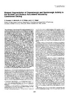
Faster responses may lead to larger changes in performance of the participant. Additionally, amplified error can also increase signal-to-noise ratios which may improve cognitive processing and self-evaluation. It has been previously verified that training performance of the patients had been improved only when the original errors had been magnified, but not when the errors were reduced or absent [11]. Hence visual error amplification training may be an effective way to promote functional motor recovery for people after stroke. However, it is important to select a proper gain K in visual error amplification. If the gain is too small, the effect of error augmentation will be quite limited; if the gain is too large, it is possible that the sensory-motor learning will become unstable, which may cause sensor inaccuracy, overcorrection and other uncertainties, and may even cause frustration and anxiety in the participants. In this work, the gain is selected as 2, which is shown to lead the best experimental result in [11]. A gain of 2 means any deviation from the desired trajectory will be displayed twice as much the real distance from the desired trajectory (Fig. 4). The participant’s performance is expected to be better when visual error augmentation method is used. However, for stroke patients, it may still happen that the patient is not capable of completing the task by himself/herself. In this case, the assistive controller described in the previous section will be activated so that robot will help the patient come back into the acceptable band to continue the task execution. Note that the errors fed back to the assistive controller are not amplified, which guarantees the robotic system works in an accurate manner. Visual Error Augmentation
4.5
3.5 3 (m) Position 2.5 2
e
1.5
e
1 0.5 0 0
0.2
0.4
0.6
time (s)
0.8
B. Results and Analysis Two female and four male participants within the age range of 25-35 years took part in the two experiments described in above. All of them were right-handed persons. The total distance and the maximum velocity were customized to meet each participant’s motor ability and physical configuration. The maximum acceleration was 0.008m/s2. These task parameters were chosen in consultation with a physical therapist who works with stroke patients at the Vanderbilt Stallworth Rehabilitation Hospital. Table 1 showed task parameters for different participants. Once these task parameters were defined, xd , x& d , xupper
visual feedback position actual position desired position
4
participant to start the tracking task in the same arm configuration. The starting arm configuration was selected as shoulder at neutral 0º position and elbow at 90º flexion position. The task required moving the arm in forward flexion to approximately 60º in conjunction with elbow extension to approximately 0º and then coming back to starting position. The release button of the hand attachment device was given to the participants in case of emergency situations during the task execution (Fig. 1- bottom middle). The participants received visual feedback of the task trajectories and their own position trajectories on a computer monitor in front of them (Fig. 1-top right). We conducted two experiments to evaluate the proposed robot-assisted rehabilitation system with the enhanced assistive controller. In both experiments, the participants used their non-dominant arms to perform the task. It was done in order to create imperfect tracking condition so that the robotic training has some room to effect improvement. In the first experiment, the aim was to evaluate the efficacy of the system with the assist-as-needed training method only. Participants were required to perform the tracking task with the robotic assistance but without the visual error augmentation training. In the second experiment, the aim was to evaluate the efficacy of the system when the visual error augmentation training method was integrated. As our purpose of this research is to apply the robot-assisted rehabilitation system to stroke patients who are not likely to complete the task by their own effort, robotic assistance was also made available in the second experiment.
and xlower trajectories were generated by reference blocks. The acceptable error band range was set as ± 5% . The position information xave , xupper _ ave , and xlower _ ave were
1
Fig. 4 Illustration of the Visual Error Augmentation
IV. EXPERIMENT AND RESULTS In this section we present the experimental procedure and the results of the experiments with unimpaired participants. A. Experiment Procedure Participants were seated in a height adjustable chair as shown in Fig. 1 (top left) and asked to place their forearm on the hand attachment device as shown in Fig. 1 (bottom left) when the starting arm configuration was fixed. The height of the PUMA 560 robotic manipulator was adjusted for each
calculated every 4 seconds using equation (2). Condition I was checked to decide the activation of the assistive controller. The idea of the assistive controller was to assist the participants as and when the patients were out of the position band, and bring them back into the acceptable position band.
466
No. 1 2
Table I Task Parameters for Each Participant Gender Task distance (m) Vmax (m/s) Male 0.25 0.02 Male 0.3 0.02
3 4 5 6
Female Male Female Male
0.25 0.25 0.25 0.3
0.02 0.025 0.02 0.025
For each experiment, participants were asked to execute the tracking task 25 times, which were grouped into 5 training groups. Thus the participant performed the required task 5 times in each training group without break. Between two training groups, the participant took a 3-5 minutes break. Additionally, two experiments were conducted with at least 7 days interval to wash out participants’ motor adaptation to the task and any other habituation effect. Before each experiment, the participant took part in a trial practice to get a basic understanding of the task. After the second experiment, the participant took part in an extra practice without error augmentation to wash out the possible sensorymotor distortion. As discussed before, in order to mimic stroke patients and achieve better training progress, participants were required to use their non-dominant hands, which were supposed to be less dexterous to execute the experiments.
augmentation training method had greatly improved the performance of the participants (Fig. 7). The decrease was statistically significant (p-value