Interaction Engineering: Taming of the CSMA Vinay Kolar
Saquib Razak
Nael B. Abu-Ghazaleh
Dept. of Computer Science, Carnegie Mellon University, Qatar.
Dept. of Computer Science, Carnegie Mellon University, Qatar.
Dept. of Computer Science, Carnegie Mellon University, Qatar, and Binghamton University, USA.
[email protected]
[email protected]
[email protected] ABSTRACT
Keywords
Carrier Sense Multiple Access (CSMA) protocols are unable to effectively arbitrate the medium in multi-hop wireless networks; problems such as hidden and exposed terminals occur frequently leading to collisions, poor performance and unfairness. CSMA networks can be optimized by careful tuning of transceiver parameters, such as transmission power and carrier sensing threshold, to maximize transmission concurrency while minimizing collisions. Existing approaches optimize these parameters by considering only some aspects of CSMA operation (e.g., considering only PHY parameters such as SINR), thus leading to suboptimal solutions. We present a new approach that leverages recent insights into the behavior of CSMA networks. Specifically, this recent work identifies that links interfere only in a few discrete interaction modes at the MAC-layer. Each interaction mode determines how the interacting links interfere with each other and leads to different performance and fairness behavior. The proposed methodology controls the transciever parameters to convert the destructive interactions into constructive ones; we call this approach Interaction Engineering. The global optimization problem is computationally infeasible and requires central solution. Therefore, we first formulate an interaction engineering model that computes the parameters based on one-to-one interaction between the links. Second, we extend the model into a distributed interaction-aware MAC protocol (I-MAC). Testbed and simulation results show that collisions and retransmissions are almost completely eliminated, leading to large improvements in throughput and delay.
Wireless, MAC, CSMA, Interference, Topology Control, Carrier Sensing
Categories and Subject Descriptors C.2.2 [COMPUTER-COMMUNICATION NETWORKS]: Network protocols
General Terms Algorithms, Experimentation, Measurement, Performance
Permission to make digital or hard copies of all or part of this work for personal or classroom use is granted without fee provided that copies are not made or distributed for profit or commercial advantage and that copies bear this notice and the full citation on the first page. To copy otherwise, to republish, to post on servers or to redistribute to lists, requires prior specific permission and/or a fee. MSWiM’10, October 17–21, 2010, Bodrum, Turkey. Copyright 2010 ACM 978-1-4503-0274-6/10/10 ...$10.00.
1. INTRODUCTION Carrier Sense Multiple Access (CSMA) is a MAC layer protocol widely used to coordinate access to the wireless medium in multihop wireless networks [1, 27]. Under CSMA, a node transmits a packet only if the channel is sensed to be idle, thus reducing interference with other concurrent transmissions. Several popular protocols, such as IEEE 802.11 [21], use CSMA since it is well-suited for distributed implementation. Senders using CSMA cannot arbitrate the wireless channel effectively, and may therefore experience poor performance and unfairness as they compete with other senders for the channel. If the sender transmits a packet when the receiver is experiencing interference, a hidden terminal occurs (the packet is lost despite the sender sensing the medium to be idle) [22]. Similarly, if the sender unnecessarily defers transmission due to sensing the channel to be busy while the receiver’s channel is idle, an exposed terminal occurs [3]. These effects, and others, can lead to suboptimal use of the channel, with poor performance and unfairness [25, 2]. Wireless MAC protocols may be viewed to be solving a optimization problem with the following objectives: (i) maximize capacity by allowing concurrent transmissions when possible, and (ii) avoid collisions and other detrimental interactions between competing flows. The general approach we take to this problem is to manipulate the interactions between the transmitting links by controlling transciever parameters to avoid harmful interactions. Specifically, each node may adjust parameters, such as transmission power and carrier sensing threshold, to achieve optimal or near-optimal operation (as defined by the objective of the MAC optimization problem). There is a complex inter-dependence between the settings chosen by each node. For example, a sender can increase transmission power to achieve higher Signal to Interference and Noise Ratio (SINR) for its link, but in the process, it creates greater interference at other receivers, thus reducing their SINR. The Carrier Sensing threshold determines the power level at which the channel is perceived as busy. Smaller values of this threshold reduce the possibility of hidden terminals, since the sender defers transmission even when there is a weak signal sensed on the channel. However, this high sensitivity may increase exposed terminals by needlessly preventing non-colliding concurrent transmissions. Hence, the complex interdependence of parameters of different nodes makes it a hard problem to optimize the interactions that occur in a CSMA network. This paper takes a new approach to optimizing the CSMA MAC problem that is based on recent insights CSMA behavior [6, 19].
These results demonstrate that interference is manifested through discrete interactions modes, rather than continuous metrics such as SINR. As a result, small changes in topology or radio parameters can significantly affect performance by converting one destructive interaction mode into another more effective one. Thus it is vital to be aware of this behavior when optimizing transciever parameters for a given network. Moreover, these studies identify that different interactions, beyond the simple hidden terminal/exposed terminal classification can arise, with substantial impact on performance. Section 2 presents more information regarding the different interaction modes that arise in CSMA networks. Although there are a number of existing studies that optimize CSMA behavior by manipulating transciever parameters, our approach differs because it includes the full range of possible MAC interactions that arise in CSMA networks. Moreover, these studies consider only a subset of topologies, parameters or protocol rules. For example, many models assume a dense random topology [26, 9], tune only carrier sensing threshold [8, 23, 5], or assume that no ACKs are sent [26, 9]. We discuss these and other related works in Section 3. In this paper, we propose CSMA Interaction Engineering: an optimization approach that identifies harmful CSMA interaction modes in arbitrary wireless scenarios and adjusts radio parameters to convert these interactions into effective ones when possible. Specifically, 1) We propose a model and centralized algorithm that eliminates undesirable interactions, while attempting to maximize the number of concurrent transmissions. We jointly optimize transmission power, carrier sensing threshold and receiver sensitivity to accomplish these goals. The approach is based on iteratively optimizing the node parameters such that each link-pair is able to achieve effective interactions with other interfering links. Our simulation and testbed results indicate that almost all detrimental interactions are successfully eliminated leading to substantial improvement in throughput, delay and energy. Section 4 describes the model and centralized algorithm. 2) We design a distributed heuristic protocol where each active node optimizes its own radio parameters based on information from their neighboring links. We discuss the issues with distributed protocol and show that it achieves performance close to the centralized algorithm. Section 5 describes the distributed protocol. We evaluate the proposed methodology in Section 6. In the scenarios we considered, we observed an average throughput improvement of around 30%, with a maximum of 60× improvement seen in individual scenarios. The paper focuses on optimizing CSMA in a single channel with constant rate. Related studies consider additional dimensions such as channel assignment [14] and transmission rate-control [9, 12]. However, we believe that optimizing interactions among nodes that coexist in a single channel forms a basic block that recurs even while considering these additional parameters. In the future, we plan to extend this model to take advantage of these additional parameters to further optimize performance. Section 7 overviews future work, and presents some concluding remarks.
2.
BACKGROUND
In this section, we briefly overview the CSMA protocol. We then overview the major interaction modes that arise in CSMA networks [6, 19]; these interactions form the basis of our approach which controls the transciever parameters to eliminate destructive interactions.
CSMA protocol. CSMA protocols such as IEEE 802.11 [21] are widely used in wireless networks. In CSMA, the sender transmits a packet only when the channel is sensed to be idle. The Carrier Sensing Threshold (CS Threshold) parameter controls the signal level above which the channel is considered busy. Senders are more aggressive when the CS threshold is large; sender transmits the packet even when nearby nodes are transmitting, reducing exposed terminals, but increasing hidden terminals. Conversely, a low CS threshold makes the senders conservative by not transmitting even when a far neighbor is transmitting, reducing hidden terminals, but increasing exposed terminals. The nodes monitor the channel and lock to any incoming signal if it is above the Receiver Sensitivity threshold (RS Threshold). Due to the possibility of collisions, and the higher probability of transmission errors, protocols such as IEEE 802.11 use acknowledgements for successfully received DATA packets. When an ACK is not received, senders use Binary Exponential Backoff (BEB) to reduce contention for the channel. IEEE 802.11 also has an optional RTS-CTS control packet exchange before the DATA packet is transmitted. However, RTS-CTS is disabled by default in current network cards because it does not eliminate many collisions from far interferers (those beyond transmission range). Interactions in CSMA networks. It is well known that CSMA networks suffer from hidden and exposed terminals [22, 3], which adversely affect the network performance. However, recent studies have shown that the picture is significantly more complicated: two competing links can interact with each other in a number of different ways that exhibit different performance and fairness characteristics. These interactions can be categorized into a few discrete categories [6, 19] with different impact on throughput, delay and fairness. Figure 1 shows the commonly occurring interactions. No Interaction (NI): Network performance is best when all active links within the network are interference free. Figure 1(a) shows two links that can be concurrently active since neither link interferes with the other link. This maximizes channel reuse and in return increases the network throughput; we refer to this state of links to be NI (No Interference). Sender Connected (SC): When the senders can sense each other’s signals, they defer concurrent transmission. The interaction between these two links is Source Connected (SC) (Figure 1(b)). Here, both the links share the capacity equally without any collisions (except when both senders transmit at exactly the same time, which is infrequent). One of the basic problems with CSMA protocols is that channel activity is detected at the sender while the effect of this activity is applicable at the receiver; we called this effect as Misplaced Carrier Sensing. This causes exposed nodes problems in SC interaction where senders are prevented from transmission concurrently because of their close proximity, although if they had transmitted together both the receivers would have successfully received their packets. This scenario is depicted in Figure 1(b). Misplaced carrier sensing, also cause hidden terminal problems, where transmitter sense the channel to be idle while receivers experience packet drops due to local interference. Hidden terminals: Traditionally, researchers have treated all forms of hidden terminals equally. Recent studies have distinguished different forms of hidden terminals with varying performance in terms of throughput and fairness [6, 18]. Consider Figures 1 (c)(d)(e) that represent different forms of hidden terminals. In Figure 1(c), node S2 is a hidden terminal for link S1 -D1 . Packets at D1 are dropped due to interference from S2 , and S1 observes regular long backoff periods. Hence S2 -D2 gains full access to the channel, and
Figure 1: Types of Interactions in CSMA. S1 -D1 suffers from extremely low throughput. This scenario called as Asymmetric Incomplete State (AIS) [6]. Another similar interaction is Symmetric Incomplete State (SIS), where both the senders are hidden terminal to other’s receiver (Figure 1(c)). This interaction severely affects the throughput of the network since both links are unable to transmit successfully. In the fourth form of hidden terminals, both destinations interfere with each other. Hence, an ACK from one destination interferes with an ongoing DATA transmission of other link. The throughput of this interaction is similar to that in SC interaction but each link suffers from short term unfairness. This interaction, called Interfering Destinations Incomplete State (IDIS), is depicted in Figure 1(e). The fifth type of hidden terminal occurs due to Capture Effect [24]. The receiver D1 locks to the signal from interferer S2 . If the source S1 transmits when D1 has locked to S2 , then D1 ignores the S1 ’s signal. This causes a packet timeout. However, the packet is received successfully if D1 locks to S1 ’s transmission, and S2 transmits at a later point in time. We refer to this interaction has Hidden Terminal with Capture (HTC) [24].
3.
MOTIVATION AND RELATED WORK
In this section, we discuss the CSMA optimization problem and its importance. We survey the related work in various dimensions that address this problem. Finally, we motivate the methodology of Interaction Engineering as a holistic approach for improving the performance of a CSMA network. The objective of the CSMA network optimization problem is to maximize the number of concurrent successful transmissions. This objective can be broken down into maximizing the concurrent transmissions, while avoiding all detrimental interactions (to ensure that these transmissions are successfully received). The previous section showed how various factors – such as topology, SNR of a link, carrier sensing range and receiver sensitivity – determine the interaction between two links, and hence decide the performance of the network. Thus, the approach we take (Interaction Engineering) controls one or more of the transciever parameters to control the interaction modes between the competing links. Several parameters – such as transmission power, CS threshold, RS threshold, transmission rate and channel selection – affect the interactions, and hence the performance of the network. Among these, we focus on the three primary parameters: transmission power, CS and RS threshold. While other parameters can be configured to further improve the performance, the primary parameters dictate the interactions that occur between nodes. For example, even in the presence of multiple channels, it is vital to configure
the primary parameters on links that operate on the same channel. Hence, configuring the primary parameters is a critical piece of the whole problem; we call the three primary parameters as interaction parameters. The complex interplay between the parameters of nodes makes CSMA optimization a challenging problem. An ideal solution is to adjust the interaction parameters of the nodes such that each link has NI interaction with other links, and all links concurrently transmit without any hidden terminals. However, collectively optimizing the parameters of all nodes to reach this best-case scenario is complex, and in some cases impossible. For example, consider the simple scenario as shown in Figure 2 (a). It is easy to tune the variables such that links A-B and C-D have NI interaction. However, the topology in Figure 2 (b) cannot adopt the same approach. The receivers are close to the sender of the other link, and hence experiences greater interference. It is impossible to configure the link parameters such that they can transmit concurrently, while still having no collisions. The best interaction in such a topology is to tune the parameters such that there is an SC interaction. In a general case, the topology and the parameters of all nodes collectively impact the performance, and should be carefully tuned to avoid detrimental effects. The inter-dependence between the performance and the parameters at different nodes is complex. Several related studies have proposed to solve different aspects of the problem by tuning power, carrier sense and receiver sensitivity. They address various problems such as topology control [5, 15, 7], effective carrier sensing [9, 23, 4, 26] and avoiding the capture effect [24]. While each study solves a particular piece of the puzzle, it fails to consider the interrelated pieces that may adversely affect the network. We compare and categorize existing models and protocols under several areas, and compare it with interaction engineering.
Assumptions about topology. Existing models alter carrier sensing under specific network structure and density [26, 9]. For example, the carrier sensing models in these studies assume a dense random network and a honey-comb structure; where transmitters are at the centers of a hexagon and interfering transmissions happen only from neighboring hexagon cells. While optimizing in such a dense network provides asymptotic bounds, it does not faithfully optimize a given arbitrary network. Such an optimization may still have hidden and exposed terminals. For example, we saw that scenario 1 and 2 in Figure 2 need specific tuning of carrier sensing to have good interactions – even if they had belonged within the same hexagonal cell. In our paper, we optimize CSMA for any arbitrary topology.
Parameter space. As explained in Section 4, the transmission power, carrier sensing threshold and receiver sensitivity of different nodes govern the CSMA network behavior are inter-dependent. Existing studies consider only a subset of parameter space. Existing topology control algorithms alter transmission power assuming constant carrier sensing threshold for all nodes [5, 14, 15, 7]. Other studies alter carrier sensing assuming that transmission power is constant [8, 23, 26, 4]. In addition, both these categories do not consider the effect of capture [24] due to improper receiver sensitivity. Models that capture only a part of the parameter space do not efficiently optimize the network. For example, consider the 4-link scenario in Figure 3. Sources 3 and 7 can be configured into NI by setting high CS threshold such that they do not sense each other and require relatively larger transmission power to counter interference of a nearby link. However, the best configuration for sources 1 and 5 is to set a relatively low CS threshold and power to enable SC interaction. Clearly, a single one-size-fits-all approach does not lead towards optimal configuration. In this paper, we carefully tune all the three interaction parameters that affect CSMA.
CSMA Rules. Studies that characterize the possible CSMA effects conclude that a notable fraction of the detrimental interactions are caused not only due to classical hidden terminal scenario, where a DATA packet by another DATA packet, but also due to detailed CSMA handshaking rules [19, 6]. For example, two-way handshaking requires proper parameter assignment not only to the sender but also to the receiver. Inappropriate or default values often introduces the possibility of DATA collision due to ACK from a neighboring link [19]. Moreover, the receiver does not carrier sense before transmitting ACK, and hence the same rules as DATA transmission cannot be applied at receivers. Existing models do not consider the common CSMA protocol rules such as two-way handshaking. Hence, the solutions are incomplete and may cause undesirable interactions. Our work proposes a framework that accounts for interaction parameters based on prominent CSMA rules. In summary, CSMA optimization is a joint optimization of several inter-dependent parameters. CSMA interactions between the links have to be optimized to maximize spatial reuse and avoid detrimental effects. However, existing models account for only a subset of the effects and parameters, and do not explicitly consider all CSMA interactions. In this paper, we propose a generic methodology for optimizing the interactions in CSMA by tuning parameters such that the links have most favorable interactions between them.
4.
LINK-PAIR ENGINEERING
In this section, we describe the problem statement and network assumptions. We formulate an optimal interaction engineering model for a pair of links. Then, we propose a centralized algorithm that extends the model for a general topology with n links.
4.1 Strategies to optimize CSMA Section 3 described the interaction parameters – transmission power, CS threshold and RS threshold – to optimize the interactions. Through simple scenarios, we now provide the main intuition for when to alter which parameter. We first discuss engineering detrimental interactions due to packet collisions (AIS, SIS and IDIS interactions). We then discuss avoiding the capture effect (HTC interactions). Consider the scenario in Figure 2 (a), where link A-B can have the several interactions with C-D based on the the interaction pa-
Figure 2: Interaction engineering to prevent collisions. rameters. Packet collisions at link C-D can be suppressed either by: (i) raising the transmission power at C-D or lowering power at A-B such that two links transmit concurrently, but do not experience collision (having NI interaction); or (ii) Creating an SC interaction between the links by altering CS threshold at A and C. Engineering the topology for NI interactions (option i), is better since it achieves higher capacity than SC interaction. However, in certain scenarios such as Figure 2 (b), tuning only the transmission power does not eliminate collisions. Increasing transmission power of A-B increases the interference at link C-D, causing collisions at C-D. In response, C-D increases its transmission power, causing greater interference at A-B, and the cycle continues without eliminating collisions. In addition to packet collisions, CSMA suffer from HTC interaction. Recall that HTC occurs when destination first “locks on” to the packet from the interferer, and thus fails to lock to the stronger signal from source. This is easily eliminated by setting the RS threshold high enough to prevent locking to interfering signal. The destination, thus, ignores the packet from interferer and eliminate HTC interactions. Hence, engineering interactions requires to first analyze specific scenario, and then decide between the choice of creating NI or SC interaction by altering transmission power or CS threshold. HTC interactions are then prevented by setting RS threshold appropriately.
4.2 Problem statement and network representation We define optimal interaction engineering as a problem that eliminates all destructive interactions (AIS, SIS, IDIS) by converting them to either NI or SC. We define favorable interactions as NI and SC (NI being more favorable than SC), since (i) NI and SC are the only two interactions with successful handshakes in CSMA protocol; and (ii) NI achieves greater capacity than SC (Figure 2). Network topology is represented with a set of nodes N . Onehop traffic between the source nodes Si and respective destination nodes Di is represented by link set L = (Si , Di ). The number of nodes and active links are denoted by N and L, respectively. We assume Two-ray Ground Reflection propagation model, where the signal received at a node b when a is transmitting at power pa mW is given by: Sab
= =
Gt Gr h2t h2r pa dθab L Cab pa ,
(1)
where dab is the distance between a and b, Gt and Gr are antenna gains of transmitter and receiver, ht and hr are antenna heights, L is the system loss, and θ is the propagation constant. We simplify
the equation by denoting the constant terms by Cab . Signal to Noise Interference Ratio (SINR) interference model is assumed, where the packet is received without errors if the ratio of signal to the noise and interference is greater than a threshold β. Even though this theoretical model is assumed in analytical calculations, our testbed experiments conclude that it is reasonable to approximate the received power as a factor of proportional to the transmission power. We measure the constants Cab between any two links a−b in our testbed, and use Equation 1 these values to calculate the RSSI for a given transmission power.
4.3 Optimal model for two links
Figure 3: A 4-link scenario
Recall that the interaction engineering problem between a pair of links is solved by carefully setting the interaction parameters: try to create an NI interaction (scenario 1 in Figure 2), and, in cases where this is not possible, create an SC interaction (scenario 2). These are the only two possible approaches to interaction engineer a pair of links. Based on this observation, we now formulate an Optimal Link Pair (OLP) model. The model first checks if the topology can be configured for an NI interaction. If it is infeasible, we set the CS threshold such that both links do not concurrently transmit. Step 1: Check for NI feasibility: We denote the two links by (s1 , d1 ) and (s2 , d2 ). If two links can be engineered to have NI interaction (e.g., scenario 1), then the SINR for each link should be greater than SINR threshold β, i.e. Ss1 d1 ≥ β, W + Ss2 d1 where W is white noise. Similarly, NI also dictates that (1) ACK from (s2 , d2 ) should not corrupt DATA of (s1 , d1 ) (to avoid IDIS interactions); and (2) DATA from a link (s2 , d2 ) should not corrupt reception of ACK at (s1 , d1 ) 1 . Hence, using Equation 1, constraints for NI can be expressed as three linear constraints for each link (s1 , d1 ): ps1 Cs1 d1 − β(ps2 Cs2 d1 ) ≥ βW, ps1 Cs1 d1 − β(pd2 Cd2 d1 ) ≥ βW, pd1 Cd1 s1 − β(ps2 Cs2 s1 ) ≥ βW.
(2)
Similarly, three constraints are expressed for link (s2 , d2 ). Further, the variables transmission power pi , CS threshold ci and RS threshold ri for node i are bounded by pi ≥ Pmin , ci ≥ W, and ri ≥ W,
(3)
where W is the white noise. We represent the vector of transmission powers by p = {p1 , p2 , . . . pN }. Similarly, vectors for CS and RS threshold is denoted by c and r, respectively. Equation 2 represents the constraints for the feasible region of transmission powers of s1 , d1 , s2 and d2 . We now present feasible regions for RS threshold and CS threshold of the nodes. If NI is feasible, the CS threshold should be set such that s1 and s2 do not sense each other. The RS threshold at the nodes should be set such that it receives the packet from its link, but does not lock to the DATA packet from other link (to avoid HTC interaction). These 1 Another possibility of collision is ACK of (s2 , d2 ) corrupting ACK of (s1 , d1 ). While this constraint can be easily added to the model, we ignore it since we have observed that the chances of two ACKs being sent at the same time is very low (around 3% in our simulations).
constraints are represented by:
ps2 Cs2 d1
cs1 > ps2 Cs2 s1 + W, + W < rd1 ≤ ps1 Cs1 d1 + W, rs1 ≤ pd1 Cd1 s1 + W.
(4)
We formulate the parameter constraints for (s2 , d2 ) in a similar way. The feasible region of the interaction parameters is defined by the constraints in Equations 2, 3, 4 and similar equations for link (s2 , d2 ). If the above constraints are feasible, the NI interaction is possible (e.g. scenario 1 in Figure 2), and we choose the interaction parameters from the feasible space. Otherwise, it is impossible to create an NI, and hence we have to prevent concurrent transmission of the links by creating SC interaction. Step 2: SC formulation: Constraints for SC are similar to the ones in NI, except for (i) CS threshold should be set such that s1 and s2 sense each other, and hence do not transmit concurrently (Equations 7), and (ii) it is sufficient if the SNR (instead of SINR) is greater than β, since the links are separated in time and there is no interference from the other link (Equations 5, 6). They are given by constraints:
cs1 r d1 rs1
ps1 Cs1 d1 ≥ βW, pd1 Cd1 s1 ≥ βW, ≤ ps2 Cs2 s1 + W, ≤ ps1 Cs1 d1 + W, ≤ pd1 Cd1 s1 + W.
(5) (6) (7) (8) (9)
Similar constraints are set for link (s2 , d2 ). In summary, OLP first checks feasibility of NI interactions and assigns interaction parameters if it is feasible (step 1). Otherwise, we create SC interaction by following step 2. Thus, we optimally interaction engineer any two-link topology by maximizing favorable interactions while avoiding detrimental interactions.
4.4 Approximate model for n-link topology We now extend the OLP model for two links to a general heuristic algorithm for n links. The main idea is to iteratively optimize all link pairs. Each link calculates the optimal interaction parameters with other links, and updates its bounds on the interaction parameters. We show that our algorithm eliminates all packet timeouts, while attempting to maximize NI interactions. We illustrate the algorithm through an example topology in Figure 3. In the optimal solution, all links can be configured to have NI interactions with each other except the link-pair 1-2 and 5-6, which have to be configured for SC. Our approach is described in Algorithm 1. We run the OLP on each link pair. Each solution to the OLP computes a feasible range for interaction parameters, thus providing n − 1 feasible regions.
Algorithm 1 Link-Pair Interaction Engineering // lb[n] = Lower bound of transmission power for node n // S[l] = Set of all links that have SC interaction with link l Initialize lb[n] = 0 and S[l] = ∅ repeat converged = false; for all link-pairs (s1 , d1 ), (s2 , d2 ) do Run OLP for (s1 , d1 ), (s2 , d2 ) ps1 , pd1 , ps2 , pd2 = Minimum transmission power assigned in OLP. Update S[(s1 , d1 )] and S[(s1 , d1 )] lb[s1 ] = max(lb[s1 ], ps1 ) Similarly update lb[d1 ], lb[s2 ], lb[d2 ]. end for if lb and S has not changed then converged = true; end if until converged for all link (i, j) do pi = lb[i]; pj = lb[j] ci = cj = Maximum CS threshold for all link (x, y) ∈ S[(i, j)] do newCs = px Cxi + W if newCs < ci then ci = newCs; end if end for ri = pj Cji + W ; rj = pi Cij + W end for return p, c, r
For example, the interaction parameters for 1-2 has three feasible regions (one with each other link-pair). The solution converges to the optimal if the feasible regions intersect. Interaction parameters for a node chosen from the intersecting region satisfies all constraints. However, if the feasible regions do not intersect, then we use a heuristic. The heuristic uses a method of optimizing transmission power first, and assigning other two interaction parameters, instead of jointly optimizing all the three interaction parameters. The intuition is to select the minimum feasible transmission power for a node, since such a choice leads to greater spatial re-use (higher possibility of NI). The minimum feasible power for a node i is recorded in lb[i]. Similarly, we also record the links with which a given link l has SC interaction in the set S[l]. For example, in Figure 3, OLPs for link 1-2 indicate that it has NI with 3-4 and 7-8, and SC with 5-6. Since 1-2 and 5-6 do not concurrently transmit (SC interaction), 1-2 needs transmission power sufficient to maintain its SNR (Equation 5). However, it needs higher power to counteract the interference from 3-4 and 7-8. Among these links, there is greater interference from 7-8. Hence, the minimum transmission power required by 1-2 to avoid all interference is dictated by 7-8, and hence we record lb[1] as the minimum feasible power in OLP between 1-2 and 3-4. Also, we update S[1-2] = {5-6} and S[5-6] = {1-2}. The recorded lb becomes the new lower bounds in the next iteration of all link pair optimization. The iterations continue until there is no change in lb and S. Then we calculate the CS and RS threshold. For example, Equation 7 is used to set CS threshold for links 1-2 and 5-6 since they have SC interaction. In our simulations, we have observed that the algorithm always converge. This is because of the non-monotonic increase of lb.
Either the algorithm finds a feasible region supporting an NI interaction between any two link-pairs, or switches to SC interaction. Once SC interaction is reached, the links no more optimize with respect to each other since they do not interfere. Hence, the transmission powers of two links are decoupled, and the algorithm converges. Our algorithm does not consider the cumulative interference from multiple links. In order to account for such cumulative interference, we optimize by setting the SINR threshold β slightly higher than the actual β. In practice, we set β as 1.2 times the actual value.
5. INTERACTION AWARE MAC The CLP algorithm is centralized and requires global information. In this section, we extend CLP to design Interaction Aware MAC (I-MAC) protocol that adapts dynamically in distributed environment. We derive the general framework from the centralized model, where link-pair problem is solved iteratively (Section 4). However, the protocol exchanges information about neighborhood links, and locally optimizes only with neighboring links. We show that such a protocol performs close to centralized solution and can adapt to dynamism such as connection initiation or termination.
Data Structures. In our protocol, each node i maintains its lower bound on transmission power lbi , in addition to the already existing variables for transmission power(pi ), CS threshold(ci ) and RS threshold (ri ). The information about the links is maintains two tables: self-links are maintained in Link Information Table (LIT) and neighboring link information is maintained in Neighboring Link Table (NLT). LIT is maintained at the source of a link. Each row consists of the tuple: < dest, lbd , Csd , Cds , numPktsSent, lastUpdateTime >, indicating the destination id, current lower bound on transmission power of destination, propagation constants between the source and destination (Csd and Cds ), number of packets that have been sent recently, and the time that it was last updated. NLT is maintained by all nodes. Each row contains < s2 , d2 , lbs2 , lbd2 , scNeighbor, ttl, lastUpdateTime >, where s2 and d2 are the source and destination of the neighboring link, and lbs2 and lbd2 are their lower bounds. The boolean variable scNeighbor indicates if the neighboring link should be configured as SC (e.g. Figure 2 (b)). The neighboring link information is propagated to a node’s neighbors if the time-to-live ttl > 0, and the time when entry was last updated is stored in by lastUpdateTime. We assume that nodes can initiate Link Measurement Protocol to measure the propagation constant (Cab in Equation 1). In our testbed, we perform link measurements [10] to calculate this variable. Such algorithms have O(N ) complexity to measure all propagation factors in a network [16], and can be invoked on demand. In our protocol, measurement can be initiated when C values for LIT or NLT needs to be updated, and the values are cached.
Procedure. Each source node updates the numPktsSent in LIT dynamically as it transmits each packet. We consider a source as active source if numPktsSent is greater than a threshold for some link in LIT. Each node maintains an epoch timer that is triggered at constant time intervals. At the end an epoch, each active source triggers two procedures:
(i) It requests the lower bound of all its destinations (lbd ), and updates the LIT. Hence, all the fields in LIT are updated. (ii) It broadcasts Link Broadcast Packet, which consists of the following information: [numLinks, LinkInfo1 , LinkInfo2 , . . .] , where link information LinkInfon contains the source, destination and their lower bounds on transmission power([s, d, lbs , lbd ]) of active links. Upon reception of the Link Broadcast packet, all active sources update their NLT. If there is some change in the NLT, then the active source initiates the calculation of interaction parameters. It runs the Algorithm 1 for the current links of the source with the links in NLT. The procedure provides interaction parameters (p, c, r) and new lower bounds on transmission power (lb) for all links. The source updates its lb and interaction parameters, and requests the destination to set the new interaction parameters. This procedure repeats until the lb of all links have converged. At this stage, there will not be any new updates to NLTs. If until a new connection initiates or an existing one terminates, the NLT is modified (because of broadcast packets from new active source, or purging of entries of old source) and hence the interaction parameters adapt to the new setting.
Disseminating link broadcast packets. As discussed earlier, each source sends link broadcast packet to its neighbors. The broadcast is transmitted at a power such that all interferers are reached. Currently, we transmit the broadcast packet at larger power (3 dBm more than the default power) since it has been observed that most of the interferers are reachable with such an improvement [11]. We also set the ttl of the link broadcast packet to 3 such that most interferers are reachable through multiple hops. Another design aspect of the current protocol is the reliable dissemination of broadcast. Once the interaction parameters of the nodes have been altered, they are configure to receive the unicast packets only from their links. Hence, the nodes might fail to intercept broadcast packet if their receiver sensitivity is set high. We implement a scheme of sending the link broadcast packets through a control channel. In our evaluation, we show the effectiveness of I-MAC in both single-channel and two channel scenarios. We plan to address this limitation of the protocol in our future work.
6.
PERFORMANCE EVALUATION
In this section, we evaluate the performance of both the centralized algorithm and I-MAC protocol. We first demonstrate the effectiveness in two link scenarios using simulation and testbeds. We then analyze the results in general n link topologies. Finally, we study the effect of interaction engineering in scenarios with multiple hops. We use QualNet [17] for simulation studies, where operate on IEEE 802.11b with 2 Mbps channel capacity.
6.1 Two-link Topologies We evaluate the effectiveness of the optimal two-link model (OLP and CLP) and I-MAC through simulations and testbed. We simulate around 400 scenarios of two links which are randomly chosen in a 1500 × 1500 m2 area. Out of these scenarios we eliminate the scenarios in which the two links never interact in the default configuration (since links are far apart). Including such scenarios obscures our results since the number of such scenarios is only a factor of network size: larger the network, greater are such scenarios. Figure 4(a) shows the interactions in IEEE 802.11b (standard case) that have been converted to more favorable interactions in
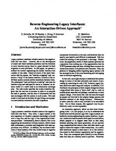
Figure 5: Testbed
I-MAC. The SC-NI conversion represent the exposed terminals, where links can be concurrently scheduled without any bad interactions. Around 34% of the scenarios suffer from exposed terminals, and all have been successfully converted to NI interaction in I-MAC. Similarly, nearly 20% of the scenarios suffer from packet timeouts (e.g., AIS, IDIS, HTC), which have all been transformed to NI interaction. The gain in throughput for each conversion is shown in Figure 4(b). It can be seen that destructive interactions (those that result in ACK timeouts) drastically affect the throughput, sometimes even reducing the link throughput to 0. I-MAC converts all the interactions to high throughput interactions. Throughput is doubled in exposed terminal scenarios as the unnecessarily blocked link is allowed to transmit. Figure 4(c) shows the cumulative network throughput improvement in different scenarios. Cumulative network throughput improves in 60% of the scenarios, with maximum throughput improvement of 350%. The CLP and I-MAC protocol converge to the optimal solution in two-link scenarios. System aspects such as unreliable broadcast accounts for around 1% of the scenarios whose performance degraded.
Testbed Evaluation. Our testbed consists of six Soekris boards with Atheros chipset and modified MadWifi driver [13], operating on IEEE 802.11a with 6 Mbps transmission rate. Our testbed is placed in an office environment with 2 rows of rooms, as shown in Figure 5. The columns are separated by plaster-board wall, and the rows by concrete pillars and glass doors. This leads to 4 reasonably effective unicast links: 1-2, 3-4, 5-6, and 3-2. All the boards are connected through an Ethernet control channel to initiate Link Measurement Protocol [10] and transmit link broadcast packets. The measurement protocol is currently initiated in the initial phase of experiment set up, where all nodes compute propagation factors C. Since the current MadWifi does not provide reliable calls to tune receiver sensitivity and carrier sensing threshold, we alter the model tune only transmit power. The CLP algorithm runs on a central coordinator, and can initiate iperf at wireless nodes to measure the throughput results. We evaluate different pairs of links and the results are shown in Table 1. Scenarios 1-5 show the classical interaction conversions where the CLP was completely successful. Channel asymmetry was observed in scenarios 6-9, where one sender could sense the other, but the converse was not true. In such cases, we CLP was partially successful in reaching its aims. Finally, we observed that the CLP was ineffective in weak links (e.g. 2-3). Most of the conversions on this link resulted in hidden terminal. We plan to extend accurate asymmetry detection and model enhancement for weak-links in our future work.
SC to NI
6
x 10
11%
Throughput Improvement wrt. Standard Case
Throughput after interaction conversion
350
Before conversion
PT to SC PT to NI
2
8%
Packet timeout scenarios Throughput (in bps)
PACKET TIMEOUTS 48%
EXPOSED TERMINALS
300
After conversion Exposed Terminal
CLP I−MAC with Reliable Broadcast I−MAC with Single Channel
250 Percentage of improvement
SC to SC
1.5
1
200 150 100 50
0.5
34%
0
0
(a) Interactions Conversion.
AIS−>NI
IDIS−>NI
HTC−>NI
−50 0
SC−>NI
(b) Throughput improvement per conversion.
20
40
60
80 100 Scenario number
120
140
160
180
(c) Throughput improvement fraction.
Figure 4: 2-Link topologies: (a) All exposed terminals (34% scenarios) and packet timeouts (denoted by PT) are converted to NI. (b) Conversion of packet timeout interactions and SC interactions lead to large throughput gains. (c) Overall network throughput improvement as much as 3.5× is observed by I-MAC protocol.
Packet Timeout SC NI
# 1 2 3 4 5 6 7 8 9 10 11 12 13
Links 1-2 4-3 4-3 6-5 2-1 3-4 1-2 3-4 2-1 4-3 2-1 6-5 2-1 5-6 1-2 6-5 1-2 5-6 3-2 6-5 3-2 5-6 2-3 5-6 2-3 6-5
Throughput (± 95%CI) Std CLP 2.912(±0.028) 5.042(±0.170) 2.955(±0.036) 5.296(±0.009) 4.033(±0.116) 5.299(±0.009) 0.000(±0.000) 5.292(±0.012) 2.852(±0.098) 2.752(±0.136) 3.024(±0.130) 2.804(±0.092) 3.040(±0.027) 3.263(±0.070) 2.645(±0.030) 3.485(±0.102) 2.684(±0.035) 3.036(±0.132) 3.016(±0.037) 3.513(±0.106) 2.410(±0.029) 4.973(±0.059) 3.678(±0.027) 3.796(±0.213) 2.601(±0.026) 2.697(±0.075) 3.111(±0.024) 3.823(±0.050) 1.478(±0.055) 2.587(±0.165) 5.253(±0.019) 5.287(±0.014) 3.503(±0.162) 5.251(±0.010) 5.293(±0.009) 5.293(±0.013) 0.122(±0.061) 3.238(±0.267) 5.298(±0.009) 5.169(±0.086) 0.101(±0.037) 0.000(±0.000) 5.293(±0.011) 5.230(±0.003) 0.024(±0.020) 0.000(±0.000) 4.910(±0.208) 5.263(±0.011) 3.010(±0.269) 0.000(±0.000) 2.997(±0.041) 5.296(±0.010)
Interaction Std CLP SC NI SC NI HTC NI AIS NI SC SC SC SC SC SC SC SC SC SC SC SC SC NI HTC HTC SC SC SC HTC IDIS SC NI NI SC NI NI NI AIS SC NI NI AIS AIS NI NI AIS AIS NI NI SC AIS SC NI
Table 1: Testbed evaluation of CLP: Scenarios 1-5 show the classical conversions. Asymmetry in sensing is observed in Scenarios 6-9. CLP fails when the links are too weak (# 10-13).
Percentage of scenarios
120 100 80 60 40 20 0
2
3
4 5 6 Number of connections
10
15
Figure 6: Interaction frequency: The two grouped bars indicate the interactions under standard case and I-MAC, respectively. Under default configuration, packet timeouts increase as the number of connection increases. I-MAC eliminates packet timeouts and exposed terminals.
6.2 General scenarios In this section, we study the effectiveness of I-MAC protocol in n-link scenarios. We first study its ability to convert interactions and then evaluate throughput and delay metrics. We simulate IEEE 802.11 (standard case) and I-MAC while varying the packet sending rates and number of connections in a 1500 × 1500 m2 network. Figure 6 shows the number of interactions seen in the standard case and I-MAC as the number of connections are varied. In the standard case, the number of packet timeouts stabilize at around 14% as the number of connections increase. I-MAC eliminates almost all packet timeouts. The exposed terminals that are converted is indicated by the difference between the SC scenarios in standard case and the ones in I-MAC. As expected, the number of connections are increased, the number of exposed terminals are reduced. This is because each link configures such that it avoids packet timeouts with any other link. If the link converts SC to NI with some nearby link, the CS threshold may induce packet timeout with another farther link. I-MAC prevents such conversions. Figure 7 shows the effect of I-MAC on overall network throughput in different scenarios for varying number of connections. As
Throughput improvement wrt. standard case
5
120
x 10
10
80 I−MAC Throughput (in bps)
Percentage of improvement
100
12
3 links 6 links 10 links 15 links
60 40 20
6
4
2
0 −20 0
8
20
40 60 Percentages of scenario
80
100
0 0
2
4 6 8 Standard Case Throughput (in bps)
10
12 5
x 10
Figure 7: Throughput improvement in n-link topologies: As the number of connections increase, larger number of scenarios have improvement with I-MAC.
Figure 9: I-MAC over Chains: Chains with low throughput improves significantly.
the number of connections increase, it is more probable to have detrimental interactions between some pair of links. Hence, I-MAC achieves improvement in larger number of scenarios as we increase the number of connections. Maximum improvements of up to 2× of overall network throughput is observed. We now evaluate the throughput and delay metrics as the packet sending rate increases. We altered packet sending rates of connections in a 6-link topology. Figure 8 shows the throughput, delay and jitter per-connection for different protocols. An average throughput improvement of around 30%, and substantial improvement in delay and jitter are achieved by I-MAC with reliable broadcast (using control channel) over the standard case. I-MAC with unreliable broadcast suffers in almost all the metrics, signifying the need for reliable dissemination of broadcast in I-MAC protocol. The large variations in these metrics is due to a number of topology dependent factors in multi-hop wireless networks. The performance that can be optimally obtained depends on how the links are placed and, hence, the extent to which it offers spatial reuse. Since we simulate random topologies, the variations are greater.
wise approach of tuning only a subset of parameters, we approach the problem from an interaction perspective; we attempt to maximize concurrency, while eliminating destructive interactions. We proposed an optimal model for two-link topologies, and an approximate algorithm for general topologies. We developed a distributed protocol based on the general algorithm that adapts dynamically to changes in the network. We evaluated the model, algorithms and protocol through simulations and testbed studies. The protocol was able to almost completely eliminate destructive interactions resulting in large improvements in throughput and delay. We plan to extend this work to improve both the base algorithm and the protocol. Currently, our model and protocol optimizes CSMA in a single channel with constant rate. We plan to formulate model and design near-optimal protocols that account for multi-rate multi-channel networks. We plan to integrate the proposed approach into an extended network we are building to detect and convert interactions in real-time. Since existing wireless cards limit the number of parameters that can be measured or altered we plan to use Software Defined Radios (SDR) to provide greater flexibility in controlling PHY and MAC parameters.
6.3 Performance under chains Thus far, we evaluated the effect of interaction engineering on single links. Interaction Engineering can be directly applied to chain topologies by considering individual links. To illustrate the use of Interaction Engineering to optimize chains, we evaluate 1000 randomly selected scenarios of two 4-hop chains, thus making sure that common categories of chain are accounted [20]. Figure 9 shows the throughput in standard IEEE 802.11 and with IMAC. Chains with more detrimental interactions have lower throughput in IEEE 802.11 benefit the most from I-MAC. The maximum observed throughput improvement was 60× more than the standard case. Thus, I-MAC can be directly employed to optimize interactions in chains.
7.
CONCLUSIONS AND FUTURE WORK
We proposed a framework to optimize CSMA wireless networks by configuring the different transciever parameters to provide greater spatial reuse, while eliminating hidden terminals. The approach is based on the observation that links in CSMA interact with each other only in a few discrete modes that have profound impact on performance and fairness. Hence, instead of looking at a piece-
Acknowledgements This work was partially supported by National Science Foundation grants CNS-0958501, CNS-0751161, and Qatar National Research Fund grant number NPRP 08-562-1-095.
8. REFERENCES [1] I. F. Akyildiz, X. Wang, and W. Wang. Wireless mesh networks: a survey. Computer Networks, 47(4):445 – 487, 2005. [2] B. Bensaou, Y. Wang, and C. C. Ko. Fair medium access in 802.11 based wireless ad-hoc networks. In MobiHoc ’00, pages 99–106, Piscataway, NJ, USA, 2000. IEEE Press. [3] V. Bharghavan, A. Demers, S. Shenker, and L. Zhang. MACAW: a media access protocol for wireless LAN’s. SIGCOMM Comput. Commun. Rev., 24(4):212–225, 1994. [4] M. Z. Brodsky and R. T. Morris. In defense of wireless carrier sense. In ACM SIGCOMM ’09, pages 147–158, New York, NY, USA, 2009. ACM. [5] Y. Gao, J. Hou, and H. Nguyen. Topology control for maintaining network connectivity and maximizing network
5
12
x 10
0.35
0.3
10
0.03 Standard Case I−MAC − Reliable Broadcast I−MAC − Unreliable Broadcast
0.025
Standard Case I−MAC − Reliable Broadcast I−MAC − Unreliable Broadcast
6
Jitter (in s)
0.02 Delay (in s)
Throughput (in bps)
0.25 8 0.2
0.15
4
0.015
0.01 0.1
2
0 0
Standard Case I−MAC − Reliable Broadcast I−MAC − Unreliable Broadcast 50
100
150
200
Packets per second
(a) Throughput
250
300
0.005
0.05
0 0
20
40
60 80 100 Packets per second
(b) Delay
120
140
160
0 0
20
40
60 80 100 Packets per second
120
140
160
(c) Jitter
Figure 8: Throughput as a function of traffic intensity: I-MAC with control channel to disseminate broadcast packets is significantly better than standard case and I-MAC without reliable broadcast.
[6]
[7]
[8]
[9]
[10]
[11]
[12]
[13] [14]
[15]
[16]
capacity under the physical model. In IEEE INFOCOM 2008, pages 1013 –1021, April 2008. M. Garetto, J. Shi, and E. W. Knightly. Modeling media access in embedded two-flow topologies of multi-hop wireless networks. In MobiCom ’05, pages 200–214, New York, NY, USA, 2005. ACM Press. D. Halperin, T. Anderson, and D. Wetherall. Taking the sting out of carrier sense: interference cancellation for wireless lans. In ACM MobiCom ’08, pages 339–350, New York, NY, USA, 2008. ACM. K. Jamieson, B. Hull, A. Miu, and H. Balakrishnan. Understanding the real-world performance of carrier sense. In ACM SIGCOMM workshop, E-WIND ’05, pages 52–57, New York, NY, USA, 2005. ACM. T.-S. Kim, H. Lim, and J. C. Hou. Improving spatial reuse through tuning transmit power, carrier sense threshold, and data rate in multihop wireless networks. In ACM MobiCom ’06, pages 366–377, New York, NY, USA, 2006. ACM. V. Kolar, S. Razak, P. Mahonen, and N. Abu-Ghazaleh. Measurement and Analysis of Link Quality in Wireless Networks: An Application Perspective. In CARMEN, IEEE INFOCOM Workshops 2010, pages 1 –6, 15-19 2010. J. Lee, S.-J. Lee, W. Kim, D. Jo, T. Kwon, and Y. Choi. RSS-based Carrier Sensing and Interference Estimation in 802.11 Wireless Networks. In IEEE SECON ’07, pages 491 –500, june 2007. T.-Y. Lin and J. Hou. Interplay of Spatial Reuse and SINR-Determined Data Rates in CSMA/CA-Based, Multi-Hop, Multi-Rate Wireless Networks. In IEEE INFOCOM 2007, pages 803 –811, may 2007. Madwifi: Linux driver for atheros cards. http://madwifi.org/. A. Muqattash and M. Krunz. Power controlled dual channel (PCDC) medium access protocol for wireless ad hoc networks. In IEEE INFOCOM 2003, volume 1, pages 470 – 480 vol.1, april 2003. A. Muqattash and M. Krunz. A single-channel solution for transmission power control in wireless ad hoc networks. In ACM MobiHoc ’04, pages 210–221, New York, NY, USA, 2004. ACM. J. Padhye, S. Agarwal, V. N. Padmanabhan, L. Qiu, A. Rao, and B. Zill. Estimation of link interference in static multi-hop
[17] [18]
[19]
[20]
[21] [22]
[23]
[24]
[25]
[26]
[27]
wireless networks. In ACM SIGCOMM IMC ’05, pages 28–28, Berkeley, CA, USA, 2005. USENIX Association. Qualnet network simulator. http://www.scalable-networks.com/. S. Razak, N. B. Abu-Ghazaleh, and V. Kolar. Modeling of two-flow interactions under sinr model in multi-hop wireless networks. In IEEE Conference on Local Computer Networks (LCN), pages 297–304, Washington, DC, USA, 2008. IEEE Computer Society. S. Razak, V. Kolar, and N. Abu-Ghazaleh. Modeling and Analysis of Two-Flow Interactions in Wireless Networks. In Wireless on Demand Network Systems and Services, WONS 2008, pages 41 –48, 23-25 2008. S. Razak, V. Kolar, N. B. Abu-Ghazaleh, and K. A. Harras. How do wireless chains behave?: The impact of MAC interactions. In ACM MSWiM ’09, pages 212–220, New York, NY, USA, 2009. ACM. The IEEE Working Group. IEEE 802.11 Wireless Local Area Networks, 2002. F. A. Tobagi and L. Kleinrock. Packet Switching in Radio Channels: Part II–The Hidden Terminal Problem in Carrier Sense Multiple-Access and the Busy-Tone Solution. IEEE Trans. on Communications, 23(12):1417–1433, 1975. M. Vutukuru, K. Jamieson, and H. Balakrishnan. Harnessing exposed terminals in wireless networks. In USENIX NSDI’08, pages 59–72, Berkeley, CA, USA, 2008. USENIX Association. K. Whitehouse, A. Woo, F. Jiang, J. Polastre, and D. Culler. Exploiting the capture effect for collision detection and recovery. In IEEE EmNets ’05, pages 45–52, Washington, DC, USA, 2005. IEEE Computer Society. S. Xu and T. Saadawi. Revealing the problems with 802.11 medium access control protocol in Multi-hop Wireless Ad hoc Networks. Comput. Networks, 38(4):531–548, 2002. X. Yang and N. Vaidya. On physical carrier sensing in wireless ad hoc networks. In IEEE INFOCOM 2005, volume 4, pages 2525 – 2535 vol. 4, march 2005. W. Ye, J. Heidemann, and D. Estrin. Medium access control with coordinated adaptive sleeping for wireless sensor networks. IEEE/ACM Trans. Netw., 12(3):493–506, 2004.