Interactive Simulation of Embolization Coils: Modeling and Experimental Validation J´er´emie Dequidt1 , Maud Marchal1 , Christian Duriez, Erwan Kerien2 , and St´ephane Cotin1 Project-Team Alcove, INRIA Nord-Europe, France1 {jeremie.dequidt,maud.marchal,christian.duriez,stephane.cotin}@lifl.fr Project-Team Magrit, INRIA Lorraine, France2
[email protected] Abstract. Coil embolization offers a new approach to treat aneurysms. This medical procedure is namely less invasive than an open-surgery as it relies on the deployment of very thin platinum-based wires within the aneurysm through the arteries. When performed intracranially, this procedure must be particularly accurate and therefore carefully planned and performed by experienced radiologists. A simulator of the coil deployment represents an interesting and helpful tool for the physician by providing information on the coil behavior. In this paper, an original modeling is proposed to obtain interactive and accurate simulations of coil deployment. The model takes into account geometric nonlinearities and uses a shape memory formulation to describe its complex geometry. An experimental validation is performed in a contact-free environment to identify the mechanical properties of the coil and to quantitatively compare the simulation with real data. Computational performances are also measured to insure an interactive simulation.
1
Introduction
Interventional radiology offers a new alternative for the treatment of brain aneurysms. An aneurysm often consists in an abnormal bulge that appears close to branching arteries. Detachable coil embolization is a minimally invasive procedure that uses the vascular network to reach the diseased vessel. The interventional radiologist starts by inserting a catheter (a long, thin and flexible tube) into the femoral artery. This catheter is then manipulated through the arterial system until the aneurysm location is reached. Once in position, the physician places one or more small coils through the catheter into the aneurysm. The body responds by forming a blood clot around the coil, thus blocking off the aneurysm and considerably reducing the risk of rupture. Although coil embolization is less invasive than open surgery, and allows treatment of cerebral aneurysms that previously were considered inoperable, such procedures are very difficult to perform and require an important experience from the interventional radiologist. This is particularly true when treating brain aneurysms, where any mistake occurring during the coil deployment or when reaching the aneurysm could lead to a brain hemorrhage. Yet, even in the case of a successfully performed procedure, the choice of the coil (shape,
length, diameter) plays a key role in the long term success of the procedure. In this context, the development of training systems or interactive planning systems, where the physician could select different coils and test their behavior in a patient-specific environment, could be very helpful. Previous work in the area of
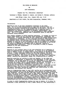
Fig. 1. (a): Coil embolization procedure: a catheter is inserted into the femoral artery to reach the brain (1) then a micro-catheter is placed near the diseased vessel and coils are inserted in the aneurysm (2). Finally, the micro-catheter is withdrawn and the body starts forming a blood clot around the coils (3). (b): two examples of coils with very different shapes: an helical shape (up) and a bird cage coil (bottom).
real-time or near real-time simulation for interventional radiology has mainly focused on training. For instance, Nowinski et al. [1], Hoefer et al. [2], Alderliesten et al. [3], or Duriez et al. [4] have proposed different approaches for modeling either catheter deformation and more generally catheter navigation in vascular networks. However, besides [3] none of these method has been validated, and currently, no real-time simulation of coils has been proposed nor validated. In this paper, we introduce in section 2 a model for simulating very thin and flexible devices such as coils. We then show how to solve in real-time the dynamic equations derived from the model by using an optimized block matrix inverse method. An original approach is also proposed for describing the complex rest shape of coils. Co-axial combinations of endovascular devices (coil inside a microcatheter for instance) are achieved using a composite model, which is based on a geometric combination of the characteristic rest shapes of each model. Section 3 presents the results of a quantitive validation study, based on a series of real coil deployments, which was performed to estimate the accuracy of our model.
2 2.1
Real-Time Model of Embolization Coil Coil Model
Different types of coils can be used for embolization. Most of them have a core made of platinum, and are sometimes coated with another material or a biologically active agent. All types are made of soft platinum wire of less than a
millimeter diameter and therefore are very soft. The softness of the platinum allows the coil to conform to the often irregular shape of the aneurysm, while the diameter, length and shape of the coil are chosen based on the shape and volume of the aneurysm, as well as the size of the neck of the aneurysm. In most cases, several coils are required to completely fill the aneurysm and maximize the chances to clot (see figure 1. The proposed coil model uses a series of serially linked beam elements, similarly as proposed by Duriez et al. [4] for simulating catheters and guidewires. However, we introduce several modifications to take into account for the particular nature of coils. A different approach for solving the mechanical system of connected beams is also proposed. To model the deformation of the coil, a representation based on three-dimensional beam theory [4], [5] is used. Since coils exhibit a more important dynamic behavior during their deployment than catheter or guidewires during navigation, we additionally present a dynamic formulation of the model. For the entire structure describing a catheter or guidewire, the global stiffness matrix K is recomputed, at each time stetp, by summing the contributions of each beam element, through its elementary stiffness matrix Ke . Assuming lumped masses at the nodes, the mass matrix M is a diagonal matrix. A damping matrix D is also introduced, thus leading to the following equilibrium equation: M¨ x + Dx˙ + Kx = f (1) where K is a band matrix due to the serial structure of the model, and x ¨, x, ˙ and x represent, respectively, the vector of accelerations, velocities and positions of the nodes, while f represents the external forces applied to the coil. The damping matrix D is defined as a linear combination of the stiffness and mass matrices D = αM + βK, known as Raleigh damping. Note that each node is described by six degrees of freedom, three of which correspond to the spatial position, and three to the angular position of the node in a global reference frame (see figure 2a). The elementary stiffness matrix Ke introduced above is a 12×12 symmetric matrix that relates spatial and angular positions of each end of a beam element to the forces and torques applied to it (see [4] or [5] for more details). Each beam stiffness matrix is initially calculated in local coordinates, defined by a reference frame associated to the first node of the beam. In this reference frame, only deformations (bending, torsion, elongation) are measured. A transformation matrix Λ is then defined to change the local frame of reference to a global coordinate system. This leads to the following relationship between Ke in local coordinates and Ke in a global frame: Ke = ΛT Ke Λ As the beam deforms, only Λ changes and needs to be recomputed, while Ke remains constant, as long as the deformation of the beam in its local frame remains small. To model a complex structure such as a coil, which undergoes large displacements, we need to discretize it as a series of beam elements to ensure that each beam deformation will remain small. Boundary conditions are specified by defining a particular translation or rotation for the first node of the model to represent user control of the device (the coil is manipulated by pushing and twisting a wire). Since the first node
of the model is constrained, the first beam equation will be used to update the local frame for the second node, thus allowing the second beam to be computed in a reference frame where no rigid transformation occurs. By repeating this process through the whole structure, we can compute Λ for each beam element and therefore determine Ke . This method is closer to the co-rotational approach [6] than the incremental approach proposed in [4] and permits to model the geometric non-linearities that occur during the deformation of the coil.
Fig. 2. Modeling of a wire using linked beam elements. (a) Given an initial rest shape and forces applied on DOFs, internal forces are computed using a local reference frame to handle large deformations. Starting from the first beam, reference frames are updated to suppress rigid transformation from the expression of the beam deformation. (b) Modification of the initial shape by moving frames or positions allows the generation of various deformed shapes. (c) A composite model (co-axial combination of two wires) is obtained by geometrically mixing different rest shapes on one geometric model.
2.2
Real-Time Computation
Equation (1) is integrated in time using a implicit integration scheme (Euler implicit) and then solved using an optimized linear solver that takes advantage of the nature of our model. All beam elements being serially connected, the resulting stiffness matrix K is a tridiagonal matrix with a band size of 12 (since
each Ke is a 12 × 12 matrix). Since the mass and damping matrices are also diagonal, we solve the linear system using the algorithm proposed by Kumar et al. [7]. The solution can be obtained in O(n) operations instead of O(n3 ). This allows computation times of less than 10 ms for a coil composed of 100 beam elements on a computer with a Core2Duo processor running at 2.66GHz. 2.3
Shapes alteration and Composite model
Devices such as catheters, guidewires and coils are not subject to elongation but mainly bending and twisting. They are also characterized by their rest shape, which plays a very important role in the delivery of the therapy. We model these complex shapes by changing the local frame at each node of the model, as illustrated in figure 2b. Obviously, an important feature is to dynamically modify theses frames at run-time to describe more complex behaviors. For instance, to simulate a coil being deployed from a micro-catheter, we avoid computing the complex interactions the take place between the coil and the micro-catheter. Instead we propose to simulate this behavior by using a composite model. The Halpin-Tsai [8] equations provide a framework to update mechanical properties of a reinforced fiber. This approach was applied to the simulation of catheters and guidewires by Lenoir et. al. [9]. In this paper, we propose an extension of this framework to take into account two or more local frames and combine them using weighted ponderation (see figure 2c) : qcmp = q1 E1 /(E1 + E2 ) + q2 E2 /(E1 + E2 ) where each qi is the quaternion representing the transfomation from local frame global frame and Ei represents the beam Young modulus of the considered rest shape. As a consequence, such ponderation will give more influence on the final composite shape to stiff materials. 2.4
Parameter Identification
Exact mechanical properties of coils are difficult to obtain since they are not shared by device manufacturers. Among the parameters required to simulate our coil model, some of them are usually provided, such as coil length, diameter of the cross section and possibly some hints about the rest shape (circle diameter for helical-shaped coil for instance). Other parameters such as volumic mass, Young modulus and Poisson ratio can be found in mechanical engineering handbooks. Coils are made of platinum and other materials such as titanium, giving us an initial guess for what Young modulus and Poisson ratio values to use. Eventually, the rest shape is the decisive parameter we need to identify because this feature is very important for embolization coils. An optimization algorithm was used to determine the Young modulus, Poisson ratio and to adapt the rest shape of the coil given some datasets of a real coil.
3
Validation Experiment and Results
Qualitative and quantitative validations have been performed in order to verify the behavior of our coil modeling. A series of volumetric angiographic datasets of
a coil deployment were used for our experimental validation. Simulations of a coil submitted to the same forces and constraints were computed and compared to the actual coil data. Through our optimization method, the unknown parameters were determined. 3.1
Experimental Setup
Our experimental setup consists of a box filled with water and a transversal fixed guide, defining the path for the catheter. The catheter is first introduced, followed by the helical coil as in the real procedure. The three-dimensional shape of the coil at different stages of the deployment is obtained from 3DXA (3D Xray angiography) images using a marching cubes algorithm. The different steps of the experiment are illustrated in figure 3. In the following section, a validation of the coil simulations is reported for three different stages of the deployment. In these experiments, the coil is only subject to a gravity force, and contacts with the box were avoided.
(a)
(b)
(c)
Fig. 3. Experimental setup: (a) the coil is deployed in a contact-free environment. (b) Volumetric data is obtained by 3DXA and a marching cube is performed to get a mesh of the real coil. (c) Central line of the coil is extracted and a continuous formulation is built using splines. Relative Energy norm error Mean total displacement Average % (SD) (mm) Stage 1 9.80% (4.05) 18.2 Stage 2 6.19 % (5.05) 24.99 Stage 3 4.17 % (1.42) 39.11 Table 1. Error measurement. The average and the standard deviation (SD) of the relative energy norm error are given in percentage in the first column. The second column contains the mean displacement of the coil for the three different steps.
3.2
Coil Parameters
A helical coil Micrus MicroCoil Platinum is used for the validation. The parameters given by the manufacturer or those which can simply deducted are: mass:
(a)
(b)
Fig. 4. (a) Visual comparison of our coil simulation (in red) with the reconstructed coil model from our experiments (in yellow) at different stages of the deployment. (b) Simulation of the deployment of a bird-cage coil in a simple virtual aneurysm using the same parameters as for the helical coil but a different rest shape.
1.28 g, length: 150 mm , radius: 0.3556 mm, helix diameter: 7 mm. This coil has an helical rest shape and it is therefore easy to create a good initial guess for our optimization method. The algorithm was applied for different datasets and the obtained parameters are: Young modulus E = 7.5 GPa, Poisson ratio ν = 0.39 and the distance between two coils of the helix is equal to 0.25 mm. The value of those parameters are consistant with the values given in the handbooks. 3.3
Error Measurement
Figure 4 shows a visual comparison between our simulated coil deployment and a reconstructed model from experimental data. Once the real coil positions have been tracked and the shape segmented for three different stages of the coil deployment, an algorithm using a B-spline formulation was applied to the real coil data to obtain a continuous description of the shape. Then, simulations of the coil were performed using the same boundary conditions as measured during the actual coil deployment. In order to compare our simulation with the actual data, the B-spline curve was descretized using the same number of points as the number of nodes in the simlation. The error metric used to validate the coil simulation is the relative energy norm error [10]. The metric is defined as the ratio of the displacement between the simulated and the real coil and the real displacement. The error is computed for each node and for the three different steps of the deployment. The results are given in table 1. The relative energy norm error is small and exhibits that our simulation is close from real data. The absolute mean distance between simulated and real positions after deployment is equal to 1mm for each stage, explaining why the error increases if the coil is deployed on a small length.
3.4
Simulation of other coils
Given the parameters found for the helical coil, we can simulate the behavior or other types of coil as our rest-shape formulation allows an easy way to generate complex geometric shapes. Figure 4b illustrates this in the case of a ”bird-cage” coil deployed inside a simplified aneurysm shape.
4
Conclusion
The model presented in this paper offers a computationnaly efficient simulation of surgical microcoils. The experimental validation against real data and the errors measured proves the accuracy of our model. Results are provided to demonstrate that our model is generic and can handle different rest shapes allowing to simulate different types of coils available from medical device manifacturers. This work is the first step towards building a realistic simulator for coil embolization. Future work will extend this experimental validation to the study of contacts between the coil and aneurysm wall and the influence of turbulent blood flow in the aneursym during coil deployment.
5
Bibliography
References 1. Nowinski, W., Chui, C.: Simulation of interventional neuroradiology procedures. In: MIAR. (2001) 87 – 94 2. Hoefer, U., Langen, T., Nziki, J., Zeitler, F., Hesser, J., Mueller, U., Voelker, W., Maenner, R.: Cathi - catheter instruction system. In: Computer Assisted Radiology and Surgery (CARS), Paris, France (2002) 101 – 06 3. Alderliesten, T.: Simulation of Minimally-Invasive Vascular Interventions for Training Purposes. PhD dissertation, Utrecht University (2004) 4. Duriez, C., Cotin, S., Lenoir, J., Neumann, P.F.: New approaches to catheter navigation for interventional radiology simulation. Computer Aided Surgery 11 (2006) 300–308 5. Przemieniecki, J.: Theory of Matrix Structural Analysis. McGraw-Hill (1968) 6. Felippa, C.A.: A systematic approach to the element independent corotational dynamics of finite elements. Technical Report CU-CAS-00-03, Center for Aerospace Structures (2000) 7. Kumar, S., Petho, A.: An algorithm for the numerical inversion of a tridiagonal matrix. Communications in Numerical Methods in Engineering 9(4) (1993) 353– 359 8. Halpin, J., Kardos, J.: The halpin-tsai equations: a review. Polymer Engineering Science 16 (1976) 344–52 9. Lenoir, J., Cotin, S., Duriez, C., Neumann, P.: Interactive physically-based simulation of catheter and guidewire. In: Second Workshop in Virtual Reality Interactions and Physical Simulations (VRIPHYS), Pisa - Italy (November 7 2005) 10. Zienkiewicz O., T.R.: The Finite Element Method. Volume Fifth Edition. Butterworth-Heinermann (2000)