Interference Mitigation based on Channel Allocation Knowledge for Dense Femtocell Scenarios Rania El Kharsa
Jad Nasreddine, Janne Riihij¨arvi, Petri M¨ah¨onen
Lebanese University and Saint Joseph University, Beirut, Lebanon Email:
[email protected]
Institute for Networked Systems RWTH Aachen University, Aachen, Germany Email: {jad, jar, pma}@inets.rwth-aachen.de
Abstract—In this paper we propose an opportunistic access procedure in an OFDMA-based femtocells scenario. The procedure allows the femtocells to provide its users with higher data rate by accessing the unused sub-channels of the macrocell. It is based on combining information from the overall system architecture with side information used to detect the unused subchannels. The proposed procedure is compatible with Long Term Evolution (LTE) standard, and provides a 20-26 % increase in user data rates in our evaluation scenarios.
I. I NTRODUCTION The rapid increase in demand for high data rate pervasive wireless communications has lead cellular network providers and equipment vendors to develop new concepts that (1) provide high data rates especially for indoor users, (2) reduce operator power consumption, (3) create new market for manufacturer and small hardware companies, and (4) are compatible with existing technologies like GSM, LTE/LTE-A, or IEEE 802.16. Furthermore, the International Telecommunication Union (ITU) has set a goal of providing 1 Gbps for beyond International Mobile Telecommunications-2000 (IMT2000) systems [1], [2], such as Long Term Evolution (LTE) advanced systems. This objective can be reached by combining advances in communications technology, smart topology design, and spectrum refarming [3]. One of the promising concepts that fulfill these requirements is the deployment of femtocells that provide services in a range of 10-30 m in homes or small business [3]–[6], enabling significant increase in network density and thereby the degree of spatial reuse. In general, femtocells will be deployed in a multi-tier topology including macro- and microcells, where the different layers either share the same frequency channels or use orthogonal ones [7]. The shared spectrum increases spectral efficiency but requires more complex interference management techniques and reliable coordination between the base stations of each layers as well as between the base stations of the different layers. Since femtocells are expected to be deployed by the users in a highly dense fashion, especially indoors, the control of the operator on the topology and the activity of the femtocells will be reduced. This will make interference control in shared spectrum a very challenging problem. Although the orthogonal spectrum allocation does not suffer from the problem of interference between the different layers, it may lead to a decrease in spectrum efficiency; even if dynamic
spectrum assignment to femto- and macrocells is applied as in [8], the dynamics of user activities in both layers will lead to sub-optimal solutions over time. In the last few years, many interesting solutions have been proposed for the interference management problem in shared spectrum and orthogonal spectrum assignment [5]–[12]. In this paper, we propose a framework that combines the advantages of both approaches, through opportunistic spectrum access. The proposed framework does not only adapt to the long-term dynamics of the macrocells as the other existing approaches, but also the short-term dynamics (i.e. at ms timescale) of the macro users by exploiting the special structure of the LTE/LTE-A frames. This makes the system more flexible and provides higher data rates. Furthermore, the proposed approach is different from the Time Domain enhanced Inter-Cell Interference Coordination concept introduced in 3GPP release 10 where part of the transmitted signal by an eNodeB is muted by sending Almost Blank Sub-frames (ABS) to allow other eNBs to transmit with lower inter-cell interference [13]. The main difference is that the ABS are created intentionally, configured semistatically, and signaled between the eNodes/HeNodeBs while the opportunistic access in our framework are created naturally and detected by the HeNodeBs in real time fashion. The framework is applied to one scenario and the results are analyzed accordingly. We show that our scheme provides a 20-26 % increase in user data rates in our evaluation scenarios compared to approaches with no opportunistic access. The rest of the paper is organized as follows. We describe our system model in detail in Section II, and then describe our resource allocation framework in Section III. The evaluation scenarios and the used simulation framework is then discussed in Section IV together with the performance evaluation results. Finally, conclusions are drawn in Section V. II. S YSTEM M ODEL AND M AIN I DEA We consider an LTE/LTE-Advanced system where the temporal resource allocation unit is a 1 ms sub-frame composed of two identical slots in terms of used resources [14] as shown in Fig. 1. This key property is exploited by the proposed opportunistic channel allocation of the femtocells. A Physical Resource Block (PRB) is defined as a set of 12 contiguous subcarriers within one slot duration. Depending on the bandwidth of the carriers assigned to the operator, the
...
Subframe 1 Subframe 2 0.5 ms Slot 1
Subframe n 1 ms
Slot 2
Control PDCCH, PCFICH PHICH 1 PRB
Reference signals Antenna 1 and 2
Data - PDSCH freq
Data time
Frequency bands
eNodeB
HeNodeB
Fig. 1: Frame structure in LTE/LTE-A systems.
Fig. 2: Channel assignment for macrocells and femtocells.
number of PRBs can range between 6 and 100, if no carrier aggregation is used. We denote the number of PRBs by N . The considered system is composed of macro- and femtocells that either use orthogonal PRBs or are assumed to be spatially distant enough to share the same spectrum without interfering each other significantly. In the first case, the femtocells use a set of PRBs that changes over time depending on traffic changes in macro- and femtocells [8]. In the second case, the pool of PRBs are shared by macro- and femtocells under the condition that the sharing is allowed if the separating distance between the base stations is higher than a given threshold. For instance, a frequency reuse of 3 can be used in the macrocells [11]. In this case, the femtocells that are in the coverage area of one macrocell will use the PRBs assigned to the other two macrocells as shown in Fig. 2. This example is considered in the following to explain the proposed approach and study its performance, but the concept can be applied in the two aforementioned scenarios. Femtocells are designed to support a low number of users, which makes the temporal changes in the traffic patterns both drastic and sporadic. In addition, data traffic is expected to be dominant in such scenarios [15]. In contrary to voice applications, data transfer is an elastic application, in that it is usually able to modify its data rate according to the available resources [16]. On one hand, this will make real-time estimation of femtocell traffic very difficult, if not impossible. On the other hand, any additional bandwidth will increase user satisfaction, and thus the service provider profits. Therefore, any spectrum partition between femto- and macrocells will be sub-optimal. In order to take into account the elasticity of data applications in femtocells, opportunistic access concept can be used. In particular, we exploit the special frame structure of the LTE/LTE-A systems. Opportunistic access to macrocell PRBs by HeNodeBs is enabled by the fact that not all PRBs will be used by the macrocells, especially during night when most of the traffic is be generated inside the buildings. In this paper, we assume that both macrocells and femtocells use Frequency Division Duplex (FDD) mode for simplifying
the evaluation process. However, the proposed framework can be easily extended to allow the use of Time Division Duplex (TDD) mode, especially for femtocells. III. F RAMEWORK D ESCRIPTION The Interference Mitigation Algorithm based on channel allocation Knowledge (IMAK) is an algorithm based on the knowledge of the real-time macrocell allocation matrix to mitigate the interference between femtocells and macrocells in an LTE network. The algorithm is based on an opportunistic access to the unused PRBs of the macrocell whenever the traffic of the femtocells becomes higher than can be supported by the allocated channels. We divide the process of PRB allocation to eNodeBs, HeNodeBs, and users is into two phases: long-term allocation and real time allocation. A. Long-term Allocation The long-term allocation is divided into two processes: Inter-layer allocation and intra-layer allocation. The former involves of the distribution of the N PRBs between macrocells and femtocells. It is done, for instance by the operation support subsystem (OSS), as explained in the previous section and depicted in Fig. 2. It should be noted that any other allocation can be also applied. The intra-layer allocation is the process of distributing the PRBs between the different base stations in each layer. The time scales of these two processes depend on the traffic dynamics. For the inter-layer allocation it is in the scale of days or months, whereas it is in the scale of hours. The allocation of PRBs to eNodeBs is based on a frequency reuse pattern. In this work the three sectors of a eNodeB use different PRBs (A frequency reuse of 1 can be also used). Therefore, N/3 PRBs will be assigned to each sector. The whole set of PRBs allocated to femtocells (i.e. 2N/3 PRBs) is used by the HeNodeBs of each building due to the low interference between different buildings. The allocation process is triggered by the activation or de-activation of a HeNodeBs. In our system, the channels assigned to a HeNodeB are not assigned to neighboring HeNodeBs, in similar
way as in frequency reuse pattern in cellular network. This will reduce the inter-femtocell interference which can be very high due to the possible short distances between femtocells. The process of choosing the neighbors depends on the number of available PRBs for each building (i.e. 2N/3). The main idea is to maximize the distance separating two HeNodeBs using the same PRB while guaranteeing that each HeNodeB will get a minimum number of PRBs Nf , which considered here to be a constant equal to 6 (Nf can be also a parameter to optimize). Therefore, the maximum number of HeNodeBs considered as neighbors should be limited to NH = ⌊(2N/3)/Nf ⌋, where ⌊.⌋ is the floor function. Since the HeNodeBs that are separated by many walls do not generate high interference, any HeNodeBs that are separated by more than 2 walls are not considered as neighboring HeNodeBs in this paper (A more advanced technique can be also used to define neighboring HeNodeBs). Based on this approach, each HeNodeB finds its NH neighboring HeNodeBs starting by the ones separated by one wall. Then the PRBs of this HeNodeBs are chosen from the pool of PRBs allocated to the femtocells in that region excluding the ones allocated to the neighboring cells. Further, each HeNodeB will be allocated a number of PRBs as potential PRBs to be used in an opportunistic way in the real-time allocation process. These PRBs are allocated in a similar way to the normal PRBs and their number is limited to No . In this work this number is equal to Nf /2 since the total number of available opportunistic PRBs is half of the available PRBs for femtocells. This limitation is considered here in order to guarantee that all HeNodeBs will have equal chances to access to opportunistic channels. Of course, this limitation can be removed through optimization techniques, but it is out of the scope of this paper. The inter-layer allocation will be normally performed by the planning tool of the network, in particular by the Operational Support Systems (OSS). The intra-cell allocation can be performed by the eNodeB for the macrocell layer while it is performed by either the eNodeB or the HeNodeB Gateway based on information stored in a local Radio Environment Map (REM) manager [17], [18] in each building, for instance. B. Real-time Allocation In the real-time allocation, each HeNodeB will assign the Nf PRBs to the active users. Here we consider that we have two types of applications requested by the users: elastic and non-elastic. The non-elastic applications here are the applications that require a fixed data rate and usually short end-to-end delay, such as voice communication. Elastic applications are the ones for which the satisfaction of the user is an increasing function of the data rate. Therefore, the HeNodeB will first allocated PRBs to the non-elastic users, and the remaining PRBs will be equally allocated to the other applications. We do not assign opportunistic PRBs to the non-elastic applications since the quality of service in these PRBs is not guaranteed because a macro user can start using them at any moment. In case the HeNodeB has at least one user requesting an elastic application, the HeNodeB will check its No oppor-
tunistic PRBs. If some of them are not used by the covering eNodeB, the HeNodeB will again distribute these PRBs between the elastic applications. In order to detect the available PRB, the HeNodeB can either sense the control channels transmitted at the beginning of each slot or it can decode the control channel of the HeNodeB in order to detect the identity of the existing macrocell and synchronize with its frames. We adopt here the second procedure. More specifically, we assume that the HeNodeB can decode the Physical Downlink Control Channels (PDCCH) transmitted in the first n OFDM symbols of the first slot of each subframe1 [20] as shown in Fig. 1. For this the HeNodeB may need to know macro users’ Radio Network Temporary identifiers (RNTIs) in order to ensure that the decoding of the allocation matrix is done without errors [21]. Since these identifiers change, the covering eNodeB can send this information to the HeNodeBs and update it when necessary. This can be done for instance through a hierarchical REM [18]. The knowledge of the RNTI is not a critical requirement for this approach. However, without this information, some error in the decoded allocation map may appear. The PDCCH contains the Downlink Control Information (DCI) that has specific fields for PRB allocation to users during the subframe. The HeNodeB should decode these fields to retrieve the complete channel allocation map of the macrocell during the subframe. This will allow the femtocell to detect the PRBs that are not used by the covering macrocell. Two approaches can be used here. In the first approach, minimum changes are required on the structure of the frame of the femto users. In this case, only the first slot of the subframe will be used by the femtocell. This slot will be shifted by n OFDM symbols with reference to the macro slot to allow the HeNodeB to decode the macrocell PDCCH. This slot overlap with the two slots of a macro subframe detected to be idle. The second slot will be empty to prevent any interference with macro users2 . This is the only required change. However, this approach will reduce the amount of additional resources acquired by the HeNodeB. To solve this problem, the femto users can be designed to be fully cognitive systems that can change their PHY and MAC in a dynamic way using dynamic policies. The required change is that the first symbols of the opportunistic slots are not used by the HeNodeB and thus no control information are sent in these slots. Hence, the n symbol shift is not anymore required and the two slots of the frames can be also used. We use the first approach with only the first slot used to keep the system compatible with 3GPP LTE/LTE-A standards. The real-time allocation is performed directly by the femtocell based on the long-term allocation. IV. S IMULATION M ODEL AND R ESULTS The IMAK performance is evaluated through a discreteevent simulator with a granularity 1 ms (i.e. one sub-frame). The results are compared to the ones given by an algorithm 1 Without 2 The
loss of generality, we consider that n = 3 in this paper as in [19]. first N − n slots of the second slots can be also used.
TABLE I: Application parameters. mean mean mean mean
silence duration talking duration service time for service time for
for ftp users for ftp users voice users data users
2 seconds 2 seconds 120 seconds 24 seconds
without opportunistic access. In the following, we only evaluate the performance of the downlink of the two layers. We considered seven trisectorized macrocells with sectors of 1/3 km radius and using 10 MHz bandwidth with center frequency 2 GHz. Each macrocell contains one building of 4 rows, 6 floors and 10 cells each. The transmit powers of the eNodeBs and HeNodeBs are 43 dBm and 20 dBm, respectively. These powers are equally distributed over the PRBs assigned to the cell. The same propagation model as in [22], [23] is used for simulations. The thermal noise density and the receiver noise figure in both layers are -174 dBm/Hz and 9 dB, respectively. We considered two types of applications in the evaluation: VoIP and FTP. The parameters of the applications and their evaluation metrics are based on the models presented in [24]. The remaining configuration parameters are summarized in Table I. The number of PRBs required by a the voice application is considered to be 1 PRB. This number has also been confirmed by the simulation results. We considered uniformly distributed users in the macrocells and inside the rooms of active femtocells. We also assumed that the macro users are only voice users whereas the femto users can be either data or voice users. The mapping between the experienced SINR by a user and the obtained data rate is adopted from Annex A.1 of [25]. Moreover, the number of the bits counted in each sub-frame is adopted from Table 111 in [4]. Based on this, the data rate using an opportunistic PRB is 0.47 times the data rate provided by a normal PRB. If fully cognitive HeNodeBs and femto users are deployed, this reduction in data rate will not appear. We have run the simulations over 24 × 104 sub-frames, which is equivalent to 4 minutes for different values of macro cell average load l, average number of data users in a femtocell n, and femtocell activation ratio a. The macrocell load is defined as the ratio between the average of simultaneously active macro users attached to an eNodeB and the number of assigned PRBs to that eNodeB (i.e. N/3). The activation ratio is defined as the ratio between the active HeNodeB and the deployed ones. The deployment ratio is 0.8, meaning that only 80% of the rooms in a building contain active HeNodeBs. The simulation results show that the number of satisfied voice users when using IMAK is similar or higher than when IMAK is not used in most of the cases. In the remaining situations, which correspond to the case of high macrocell loads (i.e. l = 0.6), the reduction in the satisfied users only for macrocell users when using IMAK is less than 2%. This degradation is due to the interference generated by the femtocells that opportunistically access the macrocell PRBs. The results also show that the number of blocked users remain approximately the same in the two cases.
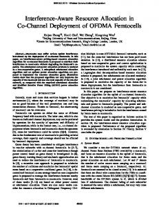
More importantly, we depict in Fig. 3 the empirical cumulative distribution functions of the provided data rates over all users. These plots show clearly the significant gain provided by IMAK in the overall capacity. On average, the increase in data rate is approximately 20 % to 26 %. The figure also shows that the gain is much higher when the activation ratio of the femtocells is lower since more opportunities are available for the femto users in this case. In addition, the increase in the macro cell load or the number of femto users in a femtocell has similar impact with or without IMAK. V. C ONCLUSIONS We have proposed an interference mitigation algorithm based on channel allocation knowledge, that allows the femtocells to access in opportunistic way the sub-channel allocated to macrocells to satisfy the increasing demand on higher data rate. The proposed algorithm exploits the fact that the behavior of the physical layer of the Long Term Evolution (LTE) physical layer is repeated over two time slots. This allows the use of the second time slot of a sub-channel assigned to a macrocell if the first time slot is detected to be idle. The main advantage of the algorithm is that although it is very simple and compatible with the standards, it can provide high increase in system performance. The simulation results have shown that the proposed algorithm can increase the data rate of data users by 20 to 26 %, depending on the environment. Furthermore, this increase is obtained without any decrease in the quality of service provided for voice users. It should be noted that the algorithm can provide higher performance if the bandwidth allocated to the system is larger, since the number of opportunistic sub-channels would increase. In addition, the allocation of the opportunistic channels in this paper follows a static scheme. A dynamic scheme is under development and is expected to significantly increase the system performance further. ACKNOWLEDGMENT The authors would like to thank RWTH Aachen University and the German Research Foundation (Deutsche Forschungsgemeinschaft, DFG) for providing financial support through the UMIC research centre. R EFERENCES [1] Recommendation ITU-R M.1645, “Framework and overall objectives of the future development of IMT-2000 and systems beyond IMT-2000,” June 2003. [2] ITU-R Report M.2134, “Requirements Related to Technical System Performance for IMT-Advanced Radio Interface(s),” Nov. 2008. [3] RealWireless report for Ofcom, “4G capacity gains, final report,” 2011. [4] “Interference management in UMTS femtocells,” Femtoforum Whitepaper, www.femtoforum.org, Dec. 2008. [5] V. Chandrasekhar, J. Andrews, and A. Gatherer, “Femtocell networks: A survey,” IEEE Comm. Magazine, vol. 46, no. 9, pp. 59–67, Sep. 2008. [6] D. Lopez-Perez, A. Valcarce, G. de la Roche, and J. Zhang, “OFDMA femtocells: A roadmap on interference avoidance,” IEEE Comm. Mag., Sep. 2009. [7] V. Chandrasekhar and J. Andrews, “Spectrum allocation in tiered cellular networks,” IEEE Trans. on Comm., Oct. 2009. [8] D. Lopez-Perez, A. Ladanyi, A. Juttner, and J. Zhang, “OFDMA femtocells: A self-organizing approach for frequency assignment,” in Proc. of IEEE PIMRC 2009, Sep. 2009, pp. 2202 –2207.
1
1 0.9
n=1 n=3
0.9 0.8
0.8 0.7
0.7
Without IMAK
Without IMAK
0.6 cdf
0.6 cdf
n=1 n=3
0.5
0.5 With IMAK
0.4
0.4 With IMAK 0.3
0.3
0.2
0.2
0.1
0.1
0 1
1.5
2 2.5 Data rate (Mbps)
3
0 0
3.5
0.5
(a) l = 0.5 and a = 0.3.
2.5
3
3.5
1 n=1 n=3
0.9
0.8
n=1 n=3
0.8
0.7
0.7
Without IMAK
Without IMAK
0.6 cdf
0.6 cdf
1.5 2 Data rate (Mbps)
(b) l = 0.5 and a = 0.6.
1 0.9
1
0.5 0.4
0.5 0.4
With IMAK
With IMAK 0.3
0.3
0.2
0.2
0.1
0.1
0 1
1.5
2 2.5 Data rate (Mbps)
3
3.5
(c) l = 0.8 and a = 0.3.
0 0
0.5
1
1.5 2 Data rate (Mbps)
2.5
3
3.5
(d) l = 0.8 and a = 0.6.
Fig. 3: Distribution of the data rate for different values of the macrocell load l, the activation ratio a, and the number of data users per femtocell with and without IMAK.
[9] M. Bennis and S. Perlaza, “Decentralized cross-tier interference mitigation in cognitive femtocell networks,” in IEEE International Conference on Communications (ICC 2011), June 2011, pp. 1 –5. [10] Y.-S. Liang, W.-H. Chung, G.-K. Ni, I.-Y. Chen, H. Zhang, and S.Y. Kuo, “Resource allocation with interference avoidance in ofdma femtocell networks,” IEEE Trans. on Veh. Tech., vol. 61, no. 5, pp. 2243 –2255, Jun. 2012. [11] T.-H. Kim and T.-J. Lee, “Throughput enhancement of macro and femto networks by frequency reuse and pilot sensing,” in IEEE International Performance, Computing and Communications Conference (IPCCC 2008), Dec. 2008, pp. 390 –394. [12] H. Claussen, “Performance of macro- and co-channel femtocells in a hierarchical cell structure,” in the 18th IEEE International Symposium on Personal, Indoor and Mobile Radio Communications (PIMRC 2007), Sep. 2007, pp. 1–5. [13] Nokia Siemens Networks, “The advanced LTE toolbox for more efficient delivery of better user experience,” Technical white paper, 2011. [14] 3GPP TS 36.300 V11.1.0, “Evolved Universal Terrestrial Radio Access ( E-UTRA) and Evolved Universal Terrestrial Radio Access Network (E-UTRAN); Overall description; Stage 2,” Mar. 2012. [15] M. Stanley. (2009, Dec.) The mobile internet report. morgan stanley. Online. Morgan Stanley. [Online]. Available: http://www.morganstanley. com/institutional/techresearch/pdfs/mobile internet report.pdf [16] F. P. Kelly, A. K. Maulloo, and D. K. H. Tan, “Rate control for communication networks: Shadow prices, proportional fairness and stability,” The Journal of the Operational Research Society, vol. 49, no. 3, pp. 237–252, Mar. 1998.
[17] A. Zalonis, N. Dimitriou, A. Polydoros, J. Nasreddine, and P. M¨ah¨onen, “Femtocell downlink power control based on radio environment maps,” in IEEE Wireless Communications and Networking Conference (WCNC 2012), Apr. 2012, pp. 390 –394. [18] J. van de Beek, T. Cai, S. Grimoud, P. M¨ah¨onen, J. Nasreddine, J. Riihij¨arvi, and B. Sayrac, “How a layered REM architecture brings cognition to today’s mobile networks,” IEEE Wireless Comm. Mag., Aug. 2012. [19] R. Love, R. Kuchibhotla, A. Ghosh, R. Ratasuk, B. Classon, and Y. Blankenship, “Downlink Control Channel Design for 3GPP LTE,” in IEEE Wireless Communications and Networking Conference (WCNC 2008), Apr. 2008, pp. 813 –818. [20] 3GPP TS 36.211 V10.4.0, “Evolved Universal Terrestrial Radio Access (E-UTRA); Physical Channels and Modulation,” Dec. 2011. [21] 3GPP TS 36.213 V10.5.0, “Evolved Universal Terrestrial Radio Access (E-UTRA); Physical layer procedures,” Mar. 2012. [22] TSG RAN WG4 (Radio) Meeting #51, “Simulation assumptions and parameters for FDD HeNB RF requirements,” 3GPP R4-092042, San Francisco, CA, May 2009. [23] 3GPP Technical Specification Group Radio Access Network, “Spatial channel model for Multiple Input Multiple Output (MIMO) simulations,” (Release 6), TR 25.996, V6.1.0, Sep. 2003. [24] F. Khan, LTE for 4G Mobile Broadband: Air Interface Technologies and Performance. Cambridge, U.K Cambridge University Press, 2009, ch. 19 - LTE performance verification, pp. 468 – 478. [25] 3GPP Technical Specification Group Radio Access Network, “Evolved Universal Terrestrial Radio Access (E-UTRA); Radio Frequency (RF) system scenarios,” (Release 10), TR 36.942, V10.3.0, Jul. 2012.