EUROPEAN COOPERATION IN
COST 272 TD-XXX
THE FIELD OF SCIENTIFIC
Thessaloniki, 20-21 June 2002
AND TECHNICAL RESEARCH ___________________________
EURO - COST
___________________________
SOURCE:
Italy (Telecom Italia Lab S.p.A.) and UK (CCSR, University of Surrey)
TASK:
WP3 (User and Service Provider Aspects)
KEYWORDS: Security, IPSEC, multicast and Satellites
Interworking between Multi-Layer IPSEC and secure multicast services over GEO satellites Marco Annoni, Gianluca Boiero, Nicoletta Salis Telecom Italia Lab S.p.A, Torino, Italy Tel. +39 011 228 5042, Fax: +39 011 228 5520 Email:
[email protected] Haitham S. Cruickshank, Michael P. Howarth and Zhili Sun CCSR, University of Surrey, UK Tel.: +44 (1483) 686007, Fax: +44 (1483) 686011 E_mail:
[email protected] Abstract: This paper presents an overview of the BRAHMS and GEOCAST projects and focuses on the security aspects of both projects. An overview of IPSEC and its variation called multi layer IPSEC is presented together with an overview of secure multicast key distribution architectures such
as Logical Key Hierarchy. Finally the paper proposes an interworking solution between multi layer IPSEC and Logical Key Hierarchy architecture.
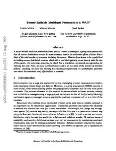
1. INTRODUCTION TO BRAHMS AND GEOCAST IST PROJECTS Demand continues to grow for broadband networks capable of supporting applications such as multimedia and information distribution, and one important component of a communications architecture that can support these services is multicast. However, terrestrial IP multicast has only slowly been deployed, due to the complexities of wide scale networks that include large numbers of multicast-enabled routers. This situation is expected to continue at least for the foreseeable future, restricting accessibility to multicast content for most potential European users. In contrast, a satellite service could simplify multicast deployment and operations/maintenance, since a single satellite hop (using only a small number of multicast enabled routers) would provide uniform delivery across the whole footprint of the EC. Satellite revenues in the next few years are increasingly likely to come from the delivery of these IPbased applications and services, either to complement terrestrial broadband services, or to offer added-value services in some niche markets. The challenge for the next generation of satellite systems is therefore to define a common basis for efficient integration of satellites in IP-centric telecommunication networks. Satellite access, rather than long-distance transport, is seen as a particularly convenient element of the overall telecommunication infrastructure, since it provides ubiquitous broadband access to anyone deploying a satellite terminal, both for single residential users and SOHO / corporate networks. Satellites are also ideally suited for delivery of multicast applications, including multimedia content distribution. The next generation of satellites will extend the coverage offered by satellite services, while increasingly utilizing standardized components to reduce terminal cost. GEO satellite systems are particularly well-suited to multicast, since a single transmission is able to be received by all terminals within a wide coverage area. If these systems can be optimised to simultaneously support multicast download of bulk content and streaming of real-time multicast content, they will provide a flexible and economic IP multicast delivery platform. In particular, there is a large interest in the study of GEO (Geostationary Earth Orbit) system solutions, which aim at providing a functionally transparent integration of satellites in Internet networks. Satellite systems based on a variety of different technologies are currently being defined and developed, and are tailored to support specific multimedia services and user requirements. Current satellite platforms are often proprietary and rely on DVB (MPEG/DVB), ATM (Asynchronous Transfer Mode), or ATM-like technologies. They cover a more or less wide range of service provisioning over transparent or regenerative satellites and support multimedia in variable proportion, whether broadcast or multicast point-to-multi-point or multi-point-to-point, or bidirectional traffic (symmetrical or asymmetrical), or point-to-point. As such the challenge for the next generation of satellite access systems is to define a common basis for efficient integration of satellites in IP-centric telecommunication networks. Therefore, a generic satellite system architecture, access system and terminal architecture, based on IP services and incorporating the above qualities, is essential. The need for standardisation in broadband satellite systems has been recognized by industry and has resulted in the setting up of a working group on Broadband Satellite Multimedia (BSM) in ETSI SES. Also these issues and network security are currently addressed by two European IST research projects: BRAHMS and GEOCAST. 1.1. Overview of BRAHMS project The IST-BRAHMS (BRoadband Access for High speed Multimedia via Satellite) project [BRAH01] has been partially funded by the EC in the frame of its FP5 and has been completed in December 2001. Its objective was to define a universal communication infrastructure for a broadband access via satellite (see Figure 1) suitable for different satellite system implementations and with the aim of harmonizing most of the common satellite access network functions. The network elements identified in the BRAHMS reference architecture are:
•
BSATs (BRAHMS Satellite Access Terminals) are routers interfacing the user segment through standard terrestrial network configurations, for example PPPoE (PPP over Ethernet), PPP/USB, or IP/Ethernet. One BSAT can directly interface with several user segments.
•
BHSs (BRAHMS Hub Stations) are routers interfacing with MANs or WANs through various technologies using link-layer and physical layer protocols such as ATM over SDH, or ATM over ADSL, or Fast Ethernet.
•
The Satellite payload can be transparent, providing only layer 1 connectivity (at frequency channel, carrier or time-slot level), or it can be regenerative thus providing layer 2 packet connectivity. The connectivity can be static or quasi-static in the case of a layer 1 transparent satellite, and more dynamic in the case of a layer 2 packet switching satellite.
•
A NCC (Network Control Centre) is responsible for control and management of the satellite access network including BSATs and BHSs. These responsibilities include satellite communications functions and allocation of resources (radio spectrum and addressing). NCC functions are often co-located with BHSs.
The satellite access flexibility of the BRAHMS architecture (e.g. for frequency, access type, orbit) is obtained by separating physically-related functions from common service functions: the higher layer Radio-Technology Independent (RTI) access network functions “hide” the lower layer RadioTechnology Dependent (RTD) functions from the user and the core network. The common RTI layers in the user (BSAT) and hub (BHS) stations in the access network support a full range of multimedia services (e.g. broadband and Internet) and connections to alternative customer premises and core networks. In this way, the transport and delivery of IP-based applications and services seamlessly complements the available terrestrial broadband services. The architecture also enables, in some niche markets, added-value services compared to terrestrial networks.
User Segment
Edge/Core Network
Access Network
Residential
NAS
Collective
Internet Backbone
BHS LAN
BSAT
Gateway to www Servers
NCC
BRAHMS BSAT: BRAHMS Satellite Access Terminal
NAS: Network Access Server
BHS: BRAHMS Hub Station
IP router
NCC: Network Control Center
Figure 1 BRAHMS architecture The BRAHMS project has developed a general model for an IP-oriented satellite architecture in which a range of existing and future satellite technologies can be accommodated and exploited by IPbased applications. Such a satellite system concept, relying directly on IP technology, brings advantages in terms of simplification of components, mechanisms and interfaces. This general model addresses not only satellite transport, but also issues related to IP networking, such as: IP QoS (Quality of Service) provision, IPv4 and IPv6 mobility support, multicast support, security and IP performance enhancement over the satellite link (header compression, TCP spoofing). These features are offered independently of the satellite technology employed.
This architecture covers several types of connectivity depending on the roles played by the satellite system: point-to-point (BSAT-BHS or BSAT-BSAT), point-to-multipoint (BHS-BSATs or BSATBSATs) or multipoint-to-multipoint. Regarding BRAHMS system security, this project did not address the RTD layers and focused only on RTI and the use of IPSEC and Multi-Layer IPSEC (ML-IPSEC) in relation to satellite Performance Enhancing Proxy (PEP), which will be presented in the section 2. The ML-IPSEC solution proposed in the BRAHMS project has been considered as one of the starting assumption by another IST project started recently, SATIP6 (Satellite Broadband Multimedia System for IPv6) [SATI01], where issues related to IP security over satellite will be further assessed taking into account also the likely evolution towards IPv6. 1.2. Overview of GEOCAST project Research has also been carried out in the area of IP multicast over satellites in the GEOCAST project (Multicast Over Geostationary EHF Satellites) [GEOC00], supported by the EU fifth framework programme [IST00] The objective of the broadband GEOCAST system is to provide a transport technology for network connectivity among end users for a wide range of services and applications. A key aspect of these broadband services is the ability of a single network to support multiple application types, such as data, video and voice. GEOCAST focuses on specific multicast applications and the infrastructure required to support them. Service providers and broadband users expect the following benefits from GEOCAST’s multicast facilities: •
Systems features matched to users specific needs (applications);
•
Adaptation of transport parameters to the different application needs: e.g. symmetry, delay sensitivity, jitter tolerance and QoS classes;
•
Efficient use of resources .
The network scenario is presented in Figure 2. The network uses an on-board cell switch with 36 MFTDMA uplinks and 36 TDM downlinks, allowing hundreds of Earth Stations (ES) per spot-beam sharing the uplink capacity, and a Network Control Centre (NCC) in charge of managing the network resources. Each ES is connected to a network carrying IP traffic [FAIR02]. A particular feature of GEOCAST is that it has been optimised for multicast delivery across different ESs and different spot beams. Like many ATM-style services, the system supports both the Constant Bit Rate (CBR) and Unspecified Bit Rate (UBR) traffic classes.
GES: Gateway Earth Station UES: User Earth Station Star multicast Mesh multicast
Corporate
UES
R
Prosumer Internet
UES
Gateway
UES GES
Figure 2 GEOCAST network scenario
R
Consumer
In addition, the GEOCAST project addresses multicast security issues over GEO satellites, and security systems are being designed both for transparent satellites and for ATM and MPEG On-Board Processing (OBP) satellites. A particular emphasis is placed on using IPSEC for end-to-end multicast security. 2. OVERVIEW OF IPSEC AND MULTI LAYER IPSEC The security architecture of the Internet Protocol known as IP security (IPSEC) is the most advanced effort in the standardization of Internet security. The IPSEC protocol suite is used to provide interoperable cryptographically-based security services (i.e. confidentiality, authentication, integrity, and non-repudiation) at the IP layer [ATKI98]. It consists of an authentication protocol: Authentication Header (AH) [ATAH98], a confidentiality protocol: Encapsulated Security Payload (ESP) [ATEP98] and it also includes an Internet Security Association Establishment and Key Management Protocol (ISAKMP) [MSST98]. These security protocols are designed for both IP version 4 (IPv4) and IP version 6 (IPv6) environments. As shown in Figure 3, the IP Authentication Header (AH) provides connectionless integrity and data origin authentication for IP datagrams. It can also provide protection against replays. The authentication header may be used, alone or in combination, with the ESP. AH authenticates slightly more information in the IP datagram than does the ESP authentication (the IP datagram header is not included in the computation of the cryptographic integrity checksum of ESP). The authentication header protocol has two modes: transport or tunnel. IPv4 Original IP header
Transport mode:
AH
TCP
Data
coverage of authentication (except for mutable fields)
IPv6: Original IP header
Hop-by-hop extensions
AH
End-to-end extensions
TCP
Data
coverage of authentication (except for mutable fields)
Tunnel mode:
IPv4 and IPv6: Encapsulating IP header
AH
Original + ext IP header fields
TCP
Data
coverage of authentication (except for mutable fields)
Figure 3 Authentication Header (AH) in transport and tunnel modes Transport mode is used only in host-to-host authentication, while tunnel mode can be used between two hosts, either host-to-gateway or gateway-to-gateway. The tunnel allows the host to delegate the security service to the gateway. This is especially interesting for companies with two private distant networks connected through the public Internet. In this mode, the IP header of the host/gateway responsible for computing/checking the AH is added while the old IP header is kept in the new IP datagram and moved after the AH. The AH does not protect mutable fields of IP datagrams (e.g., record route, timestamp, loose source routing and strict source routing options). These fields are specifically excluded from the authentication computation in order to prevent from the occurrence of authentication errors. The Encapsulating Security Payload (ESP) protocol, shown in Figure 4, provides a mix of security services: data confidentiality, data origin authentication, connectionless integrity and anti-replay. As
in the case of AH, the ESP uses a set of fields to identify the service being provided. Some of the fields are included in the ESP Header and others in the Trailer. The set of services depends on the options selected during security association establishment. ESP may be used alone or in combination with AH. It is designed to work in transport mode or in tunnel mode. ESP header IPv4
Original IP header
SPI
Seq Nr.
ESP payload
TCP
ESP trailer
Data
Padding
Auth Data
coverage of confidentiality Transport mode:
coverage of authentication ESP header
ESP payload
ESP trailer
IPv6: Original IP header
Hop-by-hop extensions
SPI
Seq Nr.
End-to-end extensions
TCP
Data
Padding
Auth Data
coverage of confidentiality coverage of authentication
Tunnel mode:
ESP header
IPv4 and IPv6: New IP header
New extensions
SPI
Seq Nr.
Original IP datagram Original IP header
TCP
ESP trailer
Data
Padding
Auth Data
coverage of confidentiality coverage of authentication
Figure 4 Encapsulated Security Payload (ESP) in transport and tunnel modes The Security Parameter Index (SPI) field identifies the security association for this datagram (unique value for a given IP destination). SPI and destination uniquely identifies a security association. Finally, the sequence number is an optional field, and is included only if the anti-replay service is selected. 2.1. IPSEC and Performance Enhancing Proxies (PEPs) Performance Enhancing Proxies (PEPs) are used to improve the performance of Internet protocols on network paths where native performance suffers due to the characteristics of a link or subnetwork [PEP01]. In most cases, security applied above the transport layer can be used with PEPs, especially transport layer PEPs. However, today, only a limited number of applications include support for the use of transport (or higher) layer security. Network (IP) layer security such as IPSEC, on the other hand, can generally be used by any application, transparently to the application. The particular problem posed by the adoption of IPSEC in satellite-based communications is that encryption hides all details of higher layer protocols, so making it impossible for any intermediate routing and switching node processing of this information. The recent development of IPSEC in IETF is incompatible with a new set of networking paradigms that place more and more controls inside the network in intermediate nodes rather than in end nodes. In particular, any service that requires knowledge of the TCP header content anywhere other than in the end host cannot function if IP packets are encrypted; such services include most firewalls, many DiffServ implementations, MPLS (Multi Protocol Label Switching), RSVP and RED (Random Early Discard). Other functions that are affected by IPSEC include TCP spoofing, header compression, Network Address Translation, TCP traffic shaping, layer 5 switching, and transparent web caching. This could certainly be an issue for any future broadband systems and, in particular, for the BRAHMS functional architecture. As a matter of fact, most of the solutions being developed to enhance the
connectionless best effort service offered by IP over a satellite link have been integrated into BRAHMS as strict requirements: •
Adoption of efficient resources management strategies able to optimise the throughput, especially at the TCP layer.
•
Introduction of Quality of Service management for multimedia applications.
IPSEC encrypts every IP datagram, including the TCP headers that contain information needed for satellite gateways to perform TCP PEP or other intelligent routing functions. Some basic rules for TCP optimisation techniques used in satellite communications and the implications they might have on the IPSEC security protocols have been pointed out by [GUVA99]. In particular, if the optimisation techniques involve intermediate routers and require read or write access to the TCP encapsulated data, the IPSEC services cannot be used without some kind of interfering with security or adaptation. Some work on the subject has been carried out recently by Hughes Network Systems [YONG99]. This IPSEC extension has been called Multi Layer-IPSEC (ML-IPSEC): it defines a complex security relationship that involves not only the sender and the receiver of a security service, but also selected intermediate nodes along the traffic stream. The main idea is to divide the IP datagram into several zones and apply different protection schemes to each zone (see Figure 5).
IP HEADER
TCP/UDP HEADER
TCP/UDP DATA
ML-IPSec: zone map
IP HEADER
IP HEADER
ESP HEADER
TCP/UDP HEADER
TCP/UDP DATA
Zone 1
Zone 2
TCP/UDP HEADER
ESP TRAILER 1
TCP/UDP DATA
Zone 1 (k1)
ESP TRAILER 2
ESP AUTH
Zone 2 (k2) Encrypted
Figure 5 ML-IPSEC datagram structure 2.2. Multi Layer IPSEC in the BRAHMS network As the security issue in the BRAHMS network has to interwork with the other performance enhancing functional aspects just mentioned, the main problem is their compatibility with ML-IPSEC. Since now the security service is provided on a “zone-by-zone” basis, individual security relationships can be used to cover each zone of the IP datagram, and then build a new type of Security Association (SA), called a Composite SA (CSA). With reference to Figure 6, when a user in Network A wants to establish a secure link with a node in Network B, the Security Gateway A (in the BSAT) establishes the necessary Security Associations with the Security Gateway B and with all authorized intermediate gateways (e.g. the security gateway in the BHS), before starting the actual data transaction. The SAs constitute different levels of security relationships related to the negotiation of security services. Before any IP datagram is sent through the untrustworthy Internet, the Security Gateway A in the BSAT encrypts and/or signs it, using an ML-IPSEC protocol. When the datagram reaches Security Gateway B, it is decrypted and/or checked
for authentication. Then it is forwarded to the final destination in the Network B. When the MLIPSEC protected datagram flows through an authorized intermediate node (e.g. BHS), if needed, a certain part of the datagram (e.g. the TCP header) may be decrypted and/or modified and reencrypted, but the other part will not be compromised. In this scheme, the BHS performs, among others, the function of ML-IPSEC PEP-Gateway, having the key needed to decrypt the TCP header part and therefore perform RSVP, TCP spoofing, header compression, etc.
Trusted Network A
Security GW A
BSAT
IPSec datagram
BHS
Security GW C
Internet
Security GW B
Trusted Network B
IP header
IP datagram IP header
IPSec header
TCP header
TCP header
K1 encryption TCP data
TCP data
K2 encryption
Figure 6 Status of the IP Datagrams in the BRAHMS Network in presence of ML-IPSEC On the other hand, the BSAT always operates as an End Host Security Gateway because it is connected to the edge of a Trusted Network. The status of the IP datagram while travelling in the network is shown in Figure 7. The different encryption and security levels applied at any specific node of the network can be easily identified. Figure 7 shows the different nodes of the BRAHMS reference architecture and the message sequence chart characterizing the encryption/decryption phases in an ML-IPSEC mode. The following steps can be identified: •
The User (Network A) asks to create a secure connection with a node in the Network B (e.g. an IP server). Before transmitting the IP-datagram, the security requirements are established (CSA) and the network gateways are informed.
•
The BSAT performs QoS management and TCP spoofing, then it authenticates and encrypts the IP datagram by using two different keys (K1 and K2). If needed, it performs header compression on the IP Header (it might be noticed that, because of the previous encryption of the whole TCP segment, the TCP header is no longer available for header compression). Finally it transmits the datagram to the BHS through the satellite.
•
Because of the encryption, IP security level is assured on the satellite link.
•
The BHS performs header decompression and operates a partial decryption on the received datagram using K1. Before forwarding the datagram, if needed, it operates QoS management and then, in order to ensure security during the transit over the Internet, re-encrypts the TCP header using K1.
The Security GW is an end-host that is able to properly decrypt all the IP datagram. When data are transmitted from the IP server (Network B) to the end user (Network A) the BSAT and the BHS
maintain their functions of End Host Security Gateway (BSAT) and of Intermediate PEP Security Gateway (BHS), but their specific processing is modified to reflect the change of direction of the data flow (e.g. TCP spoofing in this case is carried out by the BHS). It can be noticed that the partial “K1 re -encryption” occurring on the satellite link is optional and does not modify the overall ML-IPSEC scheme. In addition, the process described in Figure 6 could be simplified if some operations (i.e. header compression/decompression, spoofing, etc.) are not implemented.
USER
BSAT
SAT
BHS
Any Node
Security GW
Server
IP RSVP Spoofing Encrypt: K1,K2 Header Compr. ML-IPSec Header Decompr. Partial Decrypt: K1 (Header processing) Partial Encrypt: K1 ML-IPSec
ML-IPSec Decrypt:K1,K2 IP
Figure 7 MSC of the encryption/decryption phases in BRAHMS ML-IPSEC mode
3. IP MULTICAST SECURITY 3.1. IP multicast concept As shown in Figure 8, IP multicast is an Internet protocol that enables transmission of data packets to a group of receivers. IP multicast makes efficient use of bandwidth by setting up a mid-point between unicast traffic (one-to-one) and broadcast IP traffic (one-to-all in a network). This is well suited for one-to-many or many-to-many bulk data transfer or multimedia (audio/video) streaming transmission to a large number of heterogeneous receivers. IP multicast efficiently supports this type of transmission by enabling sources to transmit a single copy of a message to a group of interested receivers. This mode of transmission scales well with increasing number of receivers, unlike in the unicast case (one-to-one), where the source has to send an individual copy of a message to each interested receiver and so performance is limited by sender bandwidth. IP multicast is also more efficient than IP broadcasting (one-to-many), since in broadcasting a copy of a message is sent to all receivers, including receivers who may not want to receive the message. More so, in the broadcast case messages are limited to a single subnet (to avoid flooding the entire Internet) compared to the multicast case (where receivers choose to join/leave different groups as they wish). IP multicast can be described as the transmission of an IP datagram to a host group: this is a set of zero or more hosts identified by a single IP destination address. A multicast datagram is delivered to all members of its destination host group with the same best- effort reliability as regular unicast IP datagrams. The membership of a host group is dynamic; that is, hosts may join and leave groups at any time. There is no restriction on the location or number of members in a host group. A host may be a member of more than one group at a time. In addition, a single group IP address may have more
than one data stream on different port numbers (or different sockets in more than one application at the application layer).
Receivers
Router Source
Router
O
Router
Figure 8 Basic Multicast transmission module For each host group, a multicast address is allocated. Users can have group memberships by joining particular multicast groups. The membership and other information of each group is processed and maintained across the entire WAN or internetwork. A multicast tree is introduced to establish and maintain the fabric of the multicast internetwork.
TCP Applications
TCP Middleware
Transmission Control Protocol (TCP)
Multicast Applications Unreliable Multicast protocol ( UMP)
Reliable Multicast protocol ( RMP)
User Datagram Protocol (UDP)
Internet Protocol (IP)
Network Infrastructure
Figure 9 IP Multicast protocol stack In order to support native IP multicast, both the sending and receiving nodes and network infrastructure between them must be multicast enabled, including the intermediate routers. Native IP multicast at an end host requires support for IP multicast and delivery of data packets at the TCP/IP protocol stack (see Figure 9).
3.1.1.
Multicast Addressing and scoping
Multicast Internet addresses have been introduced for IP multicast to define multicast host groups. These are Class D addresses and the high order bits of their first octet are “1110”. This means that all IP Multicast-group addresses will fall in the range: 224.0.0.0 - 239.255.255.255. There are reserved link-local addresses from 224.0.0.0 to 224.0.0.255, which are used by network protocols on a local network segment and packets with them will never be forwarded by router. These reserved addresses are always transmitted with a time-to-live (TTL) of 1. This address range is used only for the destination address of IP Multicast traffic. The source address for multicast datagrams is always the unicast source address. Sources send out their datagrams to the multicast host group address that they have joined, and receivers listen on the group address for incoming packets. The term scope refers to the region in which the data unit is forwarded. The scope of IP multicast can be unlimited. However, some algorithms have been employed to limit multicast scope for the following reasons: •
Limitat flooded network regions;
•
To support multicast address reuse;
•
Ensure privacy.
Some multicast routing protocols such as DVMRP use broadcast to initiate the multicast tree. Limiting scope can prevent this temporarily flooding over the whole network. Multicast address reuse enables multicast to be used multiple times, so long as the domain of the groups does not overlap. Finally, by scoping the multicast groups, it can be helpful to guarantee a certain degree of privacy, e.g. users out of the scope cannot join the multicast group. There are two main mechanisms used for scoping: •
Scoping based on TTL value;
•
Administrative scoping.
The TTL parameter is used to specify how many routers the packet can pass before dropped. Therefore, the maximum lifetime of an IP packet can be defined when it comes in the network. Administrative scoping has not been used widely. This mechanism defines the scope of the multicast group by specifying groups of multicast addresses for different administrative regions. Only members of an administration region can join the corresponding group. 3.1.2.
Internet Group Management Protocol (IGMP) and multicast routing
IGMP is a protocol that gives a host the ability to support multicasting. It works between a host and the immediately neighbouring multicast router. The router then uses a multicast routing protocol to establish or join a multicast tree for connection to the source. The current IETF IGMP is version 2 (RFC 2236). IGMP is used to manage the multicast groups. It enables the multicast router to track the membership information by using two types of IGMP massages: host membership query and host membership report. A host membership query is sent out periodically by a multicast router to determine which multicast group has members on the local network. The query is sent to 224.0.0.1 (all multicast group members in local network), and hosts generate a corresponding host membership report to indicate to the router to which multicast group they belong. Hence the multicast router can establish a table to record the relationships of all hosts and groups. When a host want to join a multicast group, it immediately transmits a join-group report for that group rather than waiting for a query. When a host want to leave a group, it sends a leave-group report to the multicast router. IGMP only provides management services between a host and the nearest router. The multicast router employs multicast routing protocols to establish and maintain the connection between senders and receivers.
Unlike IP routing (where routing table information, stored in routers, is used to determine optimal transmission paths for forwarding messages), IP multicast routing is much more complex. In IP multicast, the sender is not concerned with the number or location of clients. Instead the network undertakes to deliver to all group members and minimise needless transmission to parts of the network where there is no receiver interest. To do this the multicast-capable designated routers construct a spanning-tree (delivery tree), replacing the simple path in unicast, which is routed at each sender to the group. The spanning-tree approach ensures that there is only one path between every pair of routers and it is free of endless loops. Routers located at the branches duplicate the incoming messages and send copies down the branches where there are group members. There are a number of multicast routing protocols which can be categorized into two classes: one is intra-domain protocols such as Distance-Vector Multicast Routing Protocol (DVMRP), Multicast Extensions to Open Shortest Path First (MOSPF), Protocol-Independent Multicast Dense Mode (PIMDM) and Sparse Mode (PIM-SM), and Core Based Trees (CBT), and the other is inter-domain protocols such as Border Gateway Multicast Protocol (BGMP). 3.2. IP multicast over satellite The development and investment in broadband communications and networks over satellite in recent years has been mainly based on three approaches: bent-pipe, ATM or ATM-like fast packet technology, and DVB for broadcasting. None of these were originally designed to support IP multicast, but they have now been adapted to support IP multicast over satellites. Therefore, there are now several obvious options to support IP, depending on the available satellite systems and technologies: (1) IP over bent-pipe (transparent) satellite; (2) IP over ATM, and; (3) IP over DVB. If networks evolve towards an all-IP solution, a further option is an all-IP satellite with on-board router. Such an option will need a significant amount of new system design, replacing the ATM and DVB switches with an on-board router, and will need to convince industry to develop and deploy satellite payload systems based on the new router technology instead of existing technologies. The benefit of an IP-router-in-the-sky approach is that the routing algorithm can be used to integrate the satellite links in an IP multicast routing tree, as first mile connections, transit connections or last mile connections. To reflect the requirements of different types of services and applications, IP multicast over satellite should address the topic of security, which is important for the widespread use of multicast and its commercial success, and the rest of this paper considers this topic. 3.3. The IP multicast model and security The anonymous-receiver model that underlies IP Multicast is attractive precisely because the distribution tree is easily extendible, subject to the resources available to the multicast routing protocol. Any host in a subnet can join a multicast group without its subnet router passing identification information about the host to other routers upstream in the distribution tree. This allows IP Multicast to scale to a large number of participating hosts. The extendibility of the distribution tree in IP Multicast makes the IP Multicast model very attractive from the perspective of scalability. However, from the perspective of security, additional mechanisms and services must be built atop the basic IP Multicast model. This decoupling of security from the IP Multicast model is advantageous, since it allows differing security models and architectures to be deployed, without affecting the multicast distribution tree which delivers the multicast data end-to-end. This decoupling is also important from the application’s perspective, since each application requires different forms of host information and other security parameters, and may deploy differing useridentification and user-authentication mechanisms.
As shown in Figure 10, there are several interrelated factors or aspects of IP Multicast that influence the approaches and mechanisms used to secure it. Of these, some broad and most relevant factors include: •
Multicast application type;
•
Group dynamics;
•
Scalability issues;
•
Underlying trust model.
Application Type
Trust Model
Group Dynamics
Figure 10 Factors affecting secure multicast system design Since these factors and others are interrelated, it is difficult to portray their specific relationships and influences. However, Figure 10 displays one view of the problem/solution space, which is made up of these factors (group dynamics falling under scalability). 4. SECURE MULTICAST OVER SATELLITES A significant issue in multicast security is key management: all members of a multicast group need to be given keys that enable them to decrypt traffic. It is then necessary update these keys occasionally, for reasons described below in Section 4.1. There are many architectures for key management, one of them being based on the IETF key management draft [HACD00]. In order to support multicast groups; the domain is divided into a number of administratively scoped “areas”. A host-member of a multicast group is defined to reside within one (and only one) of these areas. The purpose of placing host-members in areas is to achieve flexible and efficient key management, particularly in the face of the problem of changes (joins and leaves) in the membership of a multicast group. In [IYEN01], we investigated the idea of defining the satellite network as a single domain, which can be divided into administratively scoped areas. Each area could be mapped into a single spot beam. Area control keys are used to distribute group keys. However, because the system uses a set of N pairwise keys to manage key updates, the overheads of rekeying due to group membership changes are high in terms of satellite transmissions and do not scale well. This problem can be mitigated using the alternative approach of the Logical Key Hierarchy [LKHW99], which we discuss later in this Section. 4.1. Multicast rekeying issues Confidentiality is ensured by encrypting traffic sent over the satellite links using a key, referred to here as the group key. Rekeying occurs for the following reasons:
(1) The group key is updated regularly (typically every few seconds or minutes) to reduce the probability of successful cryptanalysis of the encrypted traffic. (2) The group key may also need to be changed on demand if it is determined that the key has been compromised. (3) Rekeying may be required when a new user joins the multicast group. This ensures that the user cannot decrypt encoded traffic that was sent prior to their joining (this is called reverse secrecy). (4) Rekeying may be required when an existing user departs from the multicast group. This ensures that the user cannot decrypt encoded traffic that is sent after they leave (this is called forward secrecy). For large multicast groups (that have frequent membership changes) the cost of rekeying can be significant, since satellite resources are expensive. Scalable rekeying is therefore an important problem that needs to be considered in order to support secure communications for large dynamic groups. We now proceed to investigate rekey techniques for each of the four functions listed above. Several techniques exist for rekeying (1) and (3) above: two options are for the new group key to be encrypted with either (a) the old group key, or (b) a separate “control” key negotiated during session establishment. For (2) and (4) above a different rekeying approach is required since the old key is known by at least one user who is no longer to be a recipient of the multicast transmission. We assume that as each user joins, a unique pairwise key is shared between the source and the user. Let us first consider a key management system of N pairwise keys each shared between the key manager and a user (Figure 11a). The pairwise key associations are represented by the circles and the group key is represented by the box labelled ‘A’. If the group key is changed the new group key is encrypted with each user’s unique pairwise key and then unicast to that user; each of these encrypted keys is represented by one of the lines drawn in Figure 11a. Thus for N users a total of N encrypted keys are generated and transmitted across the satellite network. The disadvantages of this approach are that it does not scale well for the large multicast groups that a satellite system can be expected to cater for, and it is expensive in its use of satellite network resources. 4.1.1.
Logical key hierarchy
A hierarchical tree [LKHW99] provides a more scalable approach. Here a tree of keys is used: in Figure 11b the keys are labelled A through O, the circles represent the pairwise keys, and the lines each represent encrypted keys sent across the network, as we shall now see. Suppose that User 11 needs to be deleted from the multicast group. Then all of the keys held by User 11 (keys F, K, N, O) must be changed and distributed to the users who need them, without permitting User 11 to obtain them or anyone else who is not entitled to them. To do this, we must replace the keys held by User 11, proceeding from the bottom up. The server chooses a new key for the lowest node, then transmits it encrypted with the appropriate daughter keys. Thus for this example, the first key replaced is Key F, and this new key will be sent encrypted with User 12's unique pairwise key. The second key replaced is Key K, which is sent encrypted with the newly replaced Key F (for User 12) and also sent encrypted with key E (for Users 9 and 10). Key N is then sent encrypted in the newly replaced Key K (for Users 9, 10, and 12) and also encrypted in key L (shared by Users 13 through 16). Finally, Key O is replaced, and this new key is sent encrypted in the newly replaced Key N (for Users 9, 10, and 12 through 16) and also separately is encrypted in key M (shared by Users 1 to 8). Since we are proceeding from the bottom up, each of the replacement keys will have been replaced before it is used to encrypt another key. The seven keys sent represent a significant saving on the 16 keys that would need to be transmitted using the flat key system of Figure 11a. In general, the number of transmissions required is the sum of the degrees of the replaced nodes. In a k-ary tree in which a sits at depth d, this comes to kd − 1 = k log k N − 1 transmissions.
The system is robust against collusion, in that no set of users together can read any message unless one of them could have read it individually. Alternatively, multiple keys can be sent in one message, provided that there exists a means for each user to determine which key in the message corresponds to which node of the hierarchy. Taking into account the per-message overheads, it can be shown that a single multicast message uses the fewest bits to transmit the new keys.
O
Group key
M Key hierarchy A
N
I
J
K
L
Group key
Key A
B
C
D
E
F
G
H
Users
Users 1 2 3 4 5 6 7 8 9 10 11 12 13 14 15 16
1 2 3 4 5 6 7 8 9 10 11 12 13 14 15 16
(a)
(b)
Figure 11 Key hierarchies: (a) N pairwise keys (left); (b) hierarchical tree (right) In the case of compromised keys, (2) above, all compromised keys must be rekeyed: The cost of this will vary between k log k ( N ) − 1 (the cost of removing one user) up to
k ( N − 1) (assuming all keys in k −1
the hierarchy are compromised). 4.2. Rekeying and security policy The security policy for each multicast group determines the frequency of group key regular updates, and whether or not rekeying is required for user joins and departs. As an example of this, there are a number of alternatives to rekeying on a user depart, and these are briefly discussed below. We assume that a user is connected to the satellite network via an earth station (ES): •
Do not rekey when a user leaves a group: if the ES is trusted not to forward data for a multicast group then this is the simplest option, involving no cost of either network traffic or key generation.
•
Disable keys in the ES when it leaves the multicast group: the ES is trusted to actively destroy the keys it holds; once it has done this it is unable to decrypt the multicast group traffic.
•
Rekey when a user departs from the multicast group: this is option (4) above. Although it is the most secure alternative, it has the disadvantage that when there are a large number of group members, changing the key on each departure may be a heavy processing load on the key server, and is unlikely to scale.
•
Periodic rekeying: this is different from option (1) above, since here the intention is to bundle together a number of departing users and effectively rekey them simultaneously. This reduces the total rekey workload and increases the scalability of the multicast group, especially large dynamic groups, as has been illustrated by the Kronos system [SETI 00].
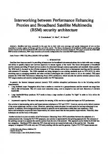
5. INTERWORKING BETWEEN ML-IPSEC AND LKH We now present an extension of the logical key hierarchy discussed in Section 4.1 that provides an efficient and scalable key management system for multicast ML-IPSEC. We consider the BRAHMS
network model of Figure 6, and analyse an IP datagram that is being multicast from a user on network A to a user (or users) on network B. We briefly review the operation of ML-IPSEC. The security gateway on the BSAT encrypts the TCP header using a group key K1, and encrypts the TCP data content using a different group key K2, giving the encrypted datagram structure shown in Figure 5. The datagram is transmitted over the satellite link and is received by the BHS; here, the Security Gateway C (in the BHS) has group key K1 and can decrypt the TCP/UDP header and perform QoS / throughput optimisation. The datagram (with the TCP header re-encrypted using K1) is then forwarded on to the destination network (or networks) where Security Gateway B holds both K1 and K2, and can therefore fully decrypt the datagram. The datagram is fully secured when transmitted over the satellite link and the public Internet In summary, it can be seen that the security gateways at the ends of the connection (i.e. at the source and at each destination of a multicast transmission) need both group keys K1 and K2. However, intermediate security gateways that are responsible for QoS and throughput optimisation only need access to group key K1 to enable them to read and if necessary change the TCP/UDP header. The two group keys K1 and K2 could be managed using two separate logical key hierarchies, but a saving can be made by integrating them into a single hierarchy as follows: Figure 12 shows the proposed key hierarchy for a set of users U1 to U8 and a set of intermediate gateways GW1 to GW8. All users and intermediate gateways are members of the multicast group. The group key K1 used to encrypt the transport layer header is at the root of the tree, and the group key K2 used to encrypt the data is one of the root’s two child keys. Recalling that in a logical key hierarchy each member only knows the keys that lie on the path from the member’s leaf node to the root, it can be seen that users have access to both K1 and K2, while gateways only have access to K1. O
M Key hierarchy
Group key K2 (for transport layer data)
I
A
Group key K1 (for transport layer header) N
J
K
B
C
D
U3 U4
U5 U6
U7 U8
E
L
F
G
H
Users U1 U2
GW1 GW2 GW3 GW4 GW5 GW6 GW7 GW8
Figure 12 Integrated LKH tree for ML-IPSEC If there are NU users and NGW intermediate gateways, then the cost of rekeying for this binary tree is 2 log 2 ( NU + N GW ) − 1 keys. For large numbers of users this is almost half the number of rekeys that would be required to rekey two separate hierarchical trees, 2 log 2 NU + 2 log 2 N GW − 2 . In general, the subtrees whose roots are at nodes M and N can each be trees of out-degree k (the two subtrees may even have different out-degrees from each other). 6. CONCLUSION This paper has examined the BRAHMS and GEOCAST security architectures, and has described IPSEC, Multi Layer IPSEC and secure multicast over satellites. The paper has illustrated the Logical Key Hierarchy (LKH), which can be used to manage key distribution for very large and dynamic multicast groups. Finally the paper presented an interworking solution between ML-IPSEC and LKH, where the end
users are put into one branch of the LKH tree and the satellite terminals are put into another branch. The root key in the LKH tree can be used for securing the transport header and a branch key secures the data content for the end users. The proposed scheme is scalable, in that the rekey effort varies with log N , and efficient, in that the number of rekeys required is half that of two separate tree hierarchies.
ACKNOWLEDGEMENT The authors gratefully acknowledge the support from the European IST Programme and the GEOCAST and BRAHMS projects.
REFERENCES [ANNO02]
M. Annoni, G. Boiero, N. Salis, “Security Issues in the BRAHMS System”. IST Mobile Communications Summit. Thessaloniki, Greece. June 2002.
[ATAH98]
R. Atkinson, “IP Authentication Header”, RFC - 2402, Nov.1998.
[ATEP98]
R. Atkinson, “IP Encapsulating Security Payload (ESP)”, RFC – 2406, Nov.1998.
[ATKI98]
R. Atkinson, “Security Architecture for the Internet Protocol”, RFC – 2401, Nov 1998.
[ATMF98]
ATM Forum, “ATM Security Specification Version 1.0 draft”, 1998.
[BRAH01]
IST-BRAHMS Web page: http://brahms.telecomitalialab.com/
[CRUI98]
Cruickshank H, Mertzanis I, Evans B. G., Leitold H and Posch R, "Securing Multimedia Services Over Satellite ATM Networks". International Journal of Satellite Communications in July-August 1998, ISSN 0737-2884, Vol 16, number 4, pages 183-195.
[FAIR02]
G. Fairhurst and A. Pietrabissa , “Better than best effort class for the GEOCAST project”, 20th AIAA conference, Montreal, Canada, 2002.
[GEOC00]
GEOCAST project home page, http://www.GEOCAST-satellite.com/
[GUVA99]
Guvara Noubir et al, “Security Issues in Internet Protocols over Satellite Links”, IEEE VTC'99 .
[HACA98]
D. Harkins, D. Carrel, “The Internet Key Exchange”, RFC – 2409, Nov. 1998.
[HACD00]
T. Hardjono, B. Cain, and N. Doraswamy, “A Framework for Group Key Management for Multicast Security,” IETF Internet draft (work in progress), Feb. 2000.
[IST00]
“Information Society Technologies Programme”, http://www.cordis.lu/ist/.
[IYEN01]
S. Iyengar, H. Cruickshank, Z. Sun, “Security issues in IP Multicast over GEO Satellites”, 19th AIAA conference, Toulouse, France, 2001.
[LKHW99]
D. Wallner et al., “Key Management for Multicast: Issues and Architectures”, IETF RFC 2627, June 1999.
[MSST98]
D. Maughan, M. Schertler, M. Schneider, J. Turner, “Internet Security Association and Key Management Protocol (ISAKMP)”, RFC – 2408, Nov. 1998.
[NADI02]
A. Nadim, J. Luo, M. Dillinger and L. Menendez, “Interworking between IP Security and Performance Enhancing Proxies for Mobile Networks”. IEEE Communications mnagzine, May 2002.
[PEP01]
RFC 3135. “Performance Enhancing Proxies Intended to Mitigate Link-Related Degradations”. June 2001. http://www.ietf.org/
[SATI01]
SATIP6 project home page, http://satip6.tilab.com
[SETI002]
S. Setia, S. Koussih, S. Jajodia, E. Harder, “Kronos: a Scalable Group Re-keying Approach for Secure Multicast”, Proc. 2000 IEEE Symposium on Security & Privacy.
[SUN02]
Z. Sun, H. Cruickshank, S. Iyengar and M. P. Howarth, “IP Multicast over Satellites Technology Challenges”, 20th AIAA conference, Montreal, Canada, 2002.
[YONG99]
Yongguang Zhang, “Multi-layer Internet Security for satellite & wireless networks”, HRL Technical Report 99-611.