[9]: Ziyad M. Salameb, Margaret A. Casacca, William A. Lynch. A Mathematical Model For Lead-Acid Battery. IEEE. Transaction on Energy Conversion, Vol.7, ...
Available online at www.sciencedirect.com
ScienceDirect Energy Procedia 36 (2013) 1076 – 1084
TerraGreen 13 International Conference 2013 - Advancements in Renewable Energy and Clean Environment
Introduction of Doubly Fed Induction Machine in an Electric Vehicle R.Babouria, D.Aouzellagb, K.Ghedamsia,b* ab
Laboratory of Renewable Energy Mastery, University of Bejaia, Bejaia 06000, Algeria
Abstract
This work is aiming to study and control of drive train of an electric vehicle based on doubly fed induction machine (DFIM), the power structure of this machine and the control strategy applied allow operating over a wide range of speed variation, for both applications: engine and recovery. Therefore the power of the machine can reach twice its rated power. After modeling different parts of the drive train a numerical simulation in MATLAB / Simulink is carried out. The results show the good performance of the vector control, and the structure of power applied to the DFIM.
access under CC BY-NC-ND license. © Authors. Published by Elsevier Ltd. Open ©2013 2013The The Authors. Published by Elsevier Ltd. Selection and/or peer-review under responsibility of the TerraGreen Academy Academy. Selection and/or peer-review under responsibility of the TerraGreen
Key words: DFIM, PWM Converters, Battery, Gearbox, control of vehicles drive train.
1. Introduction Industrial applications of variable speed drives require increasingly important performance and a maximum reliability and minimum cost. Indeed, currently the use of AC machines is becoming more common as these machines are characterized by their robustness and longevity compared to commutator machines [1-2]. Literature shows the great interest shown in the double-fed induction machine (DFIM) for various applications: as a generator for wind energy and for certain industrial applications, such as rolling and traction or propulsion maritime. Indeed, most work on this machine have been the subject of the study of the structure where the stator is directly connected to the network and the rotor powered by a power electronics converter. The advantage of this solution is that the converter is sized at 30% of the rated power of the system and therefore the variation of speed limit near the speed of synchronization [3-4]. * Corresponding author. Tel.: +213-556-463-120; fax: +0-000-000-0000 . E-mail address: rabah.babouri@yahoo a .fr.
1876-6102 © 2013 The Authors. Published by Elsevier Ltd. Open access under CC BY-NC-ND license.
Selection and/or peer-review under responsibility of the TerraGreen Academy doi:10.1016/j.egypro.2013.07.123
1077
R. Babouri et al. / Energy Procedia 36 (2013) 1076 – 1084
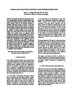
However, the objective of this work is to operate the DFIM in a wide range of speed variation, for application in a drive train of an electric vehicle; for this the machine is connected through two power converters with pulse wide modulation control (PWM), these converters are both powered by a battery, which is a key element for development of electrical vehicles, namely the energy density is low and the charge time very long [4]. In the drive train we use only one machine (DFIM) for the motorization of the vehicle, and for recovering energy during braking. The advantage of the power structure chosen is not only to operate the machine in a wide range of speed variation, but also to give to the machine the capacity to operate up to twice its rated power. So the power density is improved. Figure (1) illustrates the schematic diagram of the drive train:
DC
Wheel
Battery AC Gearbox DFIM PWM control
Defffirential
DC AC
Wheel
P Powers Fig (1): Representative diagram of the electric vehicle drive train
The ability of the DFIM to start with high torque makes possible the elimination of clutch and gearbox. The torque is the size dimensioning; therefore the machine must be heavier and bulky, so more expensive. The use of fixed ratio gearbox overcome these problems and allows to have a simple machine that can provide the required torque. The power electronic converters used for power transfer between the battery and the DFIM are sized at 100% of rated power of the machine, those are bidirectional converters with PWM control, they absorb power from the battery when the machine operates as a motor and they provide to it when the machine operates as a generator (braking). Semiconductors used depends on power level passing converters; for low powers are used IGBT. For high power converters based on IGCT or GTO semiconductors can be used. Variable-speed drives with a rated power up to 40MW (IGCT) or 100MW (GTO) have been installed. A disadvantage of these semiconductor types is their lower switching frequency, compared with IGBT’s [5]. 2. DFIM model Two-phase equivalent model of the DFIM represented in the reference (dq) linked to the rotating field is given as follows f [6-7]:
1078
R. Babouri et al. / Energy Procedia 36 (2013) 1076 – 1084
緊 懸鎚鳥 噺 迎鎚 件鎚鳥 髪 鯨砿鎚鳥 伐 降鎚 砿鎚槌 """"""""""""" 衿 懸鎚槌 噺 迎鎚 件鎚槌 髪 鯨砿鎚槌 髪 降鎚 砿鎚鳥 """""""""""""" 芹懸追鳥 噺 迎追 件追鳥 髪 鯨砿追鳥 伐 岫降鎚 伐 降追 岻砿追槌 衿 懸 噺 迎 件 髪 鯨砿 髪 岫降 伐 降 岻砿 追 追槌 追槌 鎚 追 追鳥 菌 追槌 With S: Laplace Operator In order to achieve good decoupling between the axes d and q, we define intermediate voltages as follows: 暢 懸鎚鳥 伐 懸追鳥 噺 懸痛鎚鳥 挑認 崔 暢 懸追鳥 伐 懸鎚鳥 噺 懸痛追鳥 崔
挑濡 暢
懸 挑認 追槌 暢 懸追槌 伐 懸鎚槌 挑
懸鎚槌 伐
濡
噺 懸痛鎚槌
噺 懸痛追槌
(1)
(2)
(3)
Coupling terms appear to compensate; 鶏怠鳥 , 鶏怠槌 , 鶏態鳥 , 鶏態槌 , these expressions allow to obtain relations between the intermediate voltages and the stator and rotor currents in d or q axes. So: 緊 懸痛鎚鳥 噺 迎鎚 岫な 髪 鯨劇鎚 購岻件鎚鳥 髪 鶏怠鳥 衿 懸痛鎚槌 噺 迎鎚 岫な 髪 鯨劇鎚 購岻件鎚槌 髪 鶏怠槌 (4) 芹懸痛追鳥 噺 迎追 岫な 髪 鯨劇追 購岻件追鳥 髪 鶏態鳥 衿 懸 噺 迎 岫な 髪 鯨劇 購岻件 髪 鶏 追 追 追槌 態槌 菌 痛追槌 With: Ts= Ls / Rs; stator electrical time constant; Tr = Lr / Rr; rotor electrical time constant; σ = (1-M2/ (Lr.Lr)); dispersion coefficient. The coupling terms can be expressed as follows: 暢 暢 緊 鶏怠鳥 噺 伐 挑認 迎追 件追鳥 伐 降鎚 砿鎚槌 髪 降追 挑認 砿追槌 暢 暢 衿 衿 鶏怠槌 噺 伐 迎追 件追槌 髪 降鎚 砿鎚鳥 伐 降追 砿追鳥 挑認 挑認 (5) 暢 暢 芹 鶏態鳥 噺 伐 迎鎚 件鎚鳥 髪 降鎚 砿鎚槌 伐 降追 砿追槌 挑濡 挑濡 衿 衿 暢 暢 菌 鶏態鳥 噺 伐 挑濡 迎鎚 件鎚槌 伐 降鎚 挑濡 砿鎚鳥 髪 降追 砿追鳥 From system of equations (5), the transfer’s functions following are obtained: 彫
"
怠斑 眺
濡匂 濡 緊劇鎚鳥 噺 噺 怠貸聴脹濡 蹄 蝶禰濡匂 貸牒迭匂 衿 怠斑 衿 彫濡忍 眺濡 衿 劇鎚槌 噺 噺
怠貸聴脹濡 蹄 怠斑 眺認 芹劇 噺 噺 追鳥 蝶禰認匂 貸牒鉄匂 怠貸聴脹認 蹄 衿 衿 怠斑 彫認忍 衿 眺認 劇 噺 噺 菌 追槌 蝶禰認忍貸牒鉄忍 怠貸聴脹認 蹄 蝶禰濡忍 貸牒迭忍 彫認匂
3. Converters model The matrix giving the model of powers electronics converters used is expressed as ̨æØØ欜 " "
(6)
1079
R. Babouri et al. / Energy Procedia 36 (2013) 1076 – 1084
懸銚津 な 怠 煩懸長津 晩 噺 戟待 煩 ど 戴 懸頂津 伐な
伐な な ど
ど 鯨銚 伐な晩 煩鯨長 晩 な 鯨頂
(7)
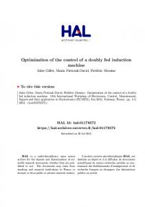
4. Battery model The model of battery used for application in electric vehicle should have the specifications as follows [8]: It should simulate the variation of the battery’s terminal voltage on certain load demand or current demand; It should be simple and require limited times for mathematical calculation and iteration; The model should be involved with as few as possible or none of the parameters that are related to the battery’s chemical process. There have been many proposals battery model; one of this is the Thevenin equivalent circuit, shown in figure (2). It is a linear electrical battery model [9]. 迎 継待
迎待 系待
荊長
+ 撃長
-
Fig(2): (2) Thevenin h i equivalent i l circuit i i off battery b
撃長 噺 継待 伐 撃頂待 伐 迎荊長 5. Vehicle Dynamics Equation governing vehicle dynamics is given as following [10]: 鳥蝶 蝶 劇追 噺 盤繋 繋追 髪 繋銚追鳥 髪 繋直 匪 堅 髪 f警塚 寧
(8)
(9)
鳥痛
繋銚追鳥 撃塚
繋追
警塚 ̌潔剣嫌岫糠岻
警塚 ̌嫌件券岫糠岻 警塚 ̌
繋追
糠
Fig (3 (3): ): Various forces applied to the vehicle
繋追 噺 鶏 系追 蝶 系追 噺 ど どな 岾な 髪 寧 峇 怠待待 Which 系追 is called the rolling resistance coefficient and P is the normal load on the Wheel. 繋銚追鳥 噺 ど の貢畦捗 系鳥 岫撃 撃塚 髪 撃栂 岻態 Where ρ is the air density, Af is the frontal area of the vehicle, Cd is aerodynamic coefficient, Vv vehicle speed and Vw is the wind speed.
(10) (11) (12) is the
1080
R. Babouri et al. / Energy Procedia 36 (2013) 1076 – 1084
繋直 噺 警塚 ̌œÆº岫c岻
(13)
Where g is the earth gravity and Mv is the total weight of the vehicle. 6. Vector control of the DFIM A vector controlled doubly fed induction machine is an attractive solution for high restricted speed rang electric drive and generation application, it consists in guiding an electromagnetic flux of the DFIM along the axis d or q.[5] In our case we choose the direction of reference (d,q) according to the direct stator flux vector 剛鎚鳥 , so the model of steady DFIM will be simplified as follows:
懸鎚鳥 噺 迎鎚鳥 件鎚鳥 緊懸 噺迎 件 髪降 剛 鎚槌 鎚 鎚槌 鎚 鎚鳥 懸 噺 迎 件 伐 降 剛追槌 追鳥 追 追鳥 追 芹 菌懸追槌 噺 迎追 件追槌 髪 降追 剛追鳥
(14)
Such as:
降追 噺 降鎚 伐 降 (15) The magnetization of machine is assured by the rotor direct current, so the stator current in the d axis is taken to zero (件鎚鳥 噺 ど ). The current and voltage in this line are then in phase: 懸鎚槌 噺 懸鎚 and 件鎚槌 噺 件鎚 (16) In this case we obtain a unity power factor at the stator, so the stator reactive power is zero Qs = 0.These simplifications lead to the electromagnetic torque expression: 劇勅陳 噺 喧剛鎚 件鎚槌 (17)
From the expressions of equations which have been established, we can draw a connection summary table setting the objectives of the control strategy with the references of action variables involved: Objectifs
剛鎚鳥 噺 剛鎚 噺 剛鎚津 剛鎚槌 噺 ど
芸鎚 噺 ど 岫潔剣嫌砿 噺 な岻 茅 劇勅陳 噺 劇勅陳
References 茅 件追鳥 噺
剛鎚津 警
詣鎚 件 警 鎚槌貸追é捗 茅 件鎚鳥 噺ど 茅 劇勅陳 茅 件鎚槌 噺 計脹勅陳
茅 件追槌 噺伐
Table (1): control strategy applied to the DFIG model
7. Powers distribution The distribution of stator and rotor active powers is a requirement in the control strategy to be applied. Indeed, this allows increasing the range of speed variation and the power density of the machine. Such as if the stator and rotor resistance windings terms are neglected, the following relationship is imposed: 牒濡
牒認
噺
摘濡
摘認
(18)
Therefore, the stator and rotor active powers distribution, involve the stator and rotor pulses distribution and vice versa. Working with a slip g = -1 we obtain the following relationship: 摘濡 貸摘 摘 噺 認 噺 伐な (19) 摘濡
So:
摘濡
1081
R. Babouri et al. / Energy Procedia 36 (2013) 1076 – 1084 摘
降鎚 噺 伐降追 噺 賑 (20) 態 The diagram representing the complete system with the control strategy applied is given by figure (7). is_abc abc bcc is
AC Ω
*
Whee e l
+-
Geearbox x
Deffirentiall
+ Battery -
DC
Ω DF D FIM M
P M PW generator
PI Tem*
ib
ir_ab _a a c Wheel
ir AC C
ab bc
φ*
d dq
DC vs*_dq
Reffereence c s currents calculati tion ti on n
Cu C urrents ttss control Repartition off R pullsation oon n
降鎚
降追
vs*_abc bcc
d dq vr*_dq
1/ss
abc bcc
PWM M generator
vr*_abc bcc
肯鎚
肯追
Fig (4): Control diagram of the electric vehicle drive train
8. Simulation results A speed control with pulses repartition 岫嫌健件喧 噺 伐な岻 is applied to the DFIM for a path of a road with variable slopes. The overall system simulation is performed on the MATLAB / Simulink, the following figures show the simulation results: DFIM speed and reference speed (rpm)
3500 3000 2500 2000 1500 1000 500 0 -500
0
1
2
3
4 t (s)
5
6
7
DFIM, reference and resistance torque (N.m)
Fig (5): DFIM speed and reference speed (rpm) 800 :Cem (N.m) :Cem*(N.m) :Cr (N.m)
600 400 200 0 -200 -400 -600 -800
0
1
2
3
4 t ((s))
5
6
Fig (6): DFIM, reference, and resistance torque (N.m)
7
8
1082
R. Babouri et al. / Energy Procedia 36 (2013) 1076 – 1084 5
x 10
Stator, rotor and battery powers (W)
3
2
1
0
-1
-2
0
1
2
3
4 t(s)
5
6
7
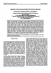
Fig (7): Stator, rotor and battery powers (W)
Stator and rotor pulsations (rd/s)
400 300 200 100 0 -100 -200 -300 -400
0
1
2
3
4 t (s)
5
6
7
Fig (8): Stator and rotor pulsations (rd/s) 620
Battery voltage (V)
600 580 560 540 520 500
0
1
2
3
4 t (s)
5
6
7
Fig (9): Battery voltage (V)
9.
Results interpretation According to the simulation results it is noted that the DFIM operates over a wide range of speed variation (twice the nominal speed), while following the reference imposed. The distribution of pulses applied for control of DFIM has allowed to have the distribution of stator and rotor actives powers, however, there is a slight difference and this is due to the stator resistance that is greater than the rotor resistance, and we note that the total power exchanged between the battery and DFIM equal to the sum of the stator and rotor actives powers. Indeed, when the driver requests the machine to beat a rib with a given speed the, DFIM can provide power equal to twice its rated power. So for positive slopes the driver requests the DFIM to provide the torque required to overcome the resistive torque imposed by the vehicle, so the machine is operating in
R. Babouri et al. / Energy Procedia 36 (2013) 1076 – 1084
motor mode, and absorbs power from the battery, for negative slopes (braking) the DFIM operates in generator mode and recharges the battery. 10. Conclusion The aim of this work is to integrate DFIM in a drive train of an electric vehicle and show its performances. Indeed, the simulation results obtained show that the DFIM can operate over wide range of speed variation, which allows to reduce the size of gearbox which is complicated and very expensive systems. And the power of the machine rises up twice of its rated power, which allows to increase its power density. Seen these benefit the DFIM is a very good alternative for use in a drive train of electric vehicles.
Nomenclature 畦捗 : Frontal area of the vehicle 系待 : Battery capacity
系鳥 : Aerodynamics coefficient 繋銚追鳥 : Aerodynamic force
繋直 : Gravitational strength 繋追 : rolling force
継待 : Open circuit voltage 訣: Earth gravity
荊長 : Battery current
件鎚鳥 件鎚槌 件追鳥 件追槌 : Direct and quadrature of stator and rotor currents 詣鎚 ,詣追 : Stator and rotor inductances 警: Mutual inductance
警塚 : Vehicle total weight
迎: Internal battery resistance 堅: Wheels radius
迎鎚 ,迎追 : Stator and rotor resistances 劇勅陳 : Electromagnetic torque 茅 劇勅陳 : Reference torque
撃頂待 : The double layer capacity voltage
懸鎚鳥 懸鎚槌 懸追鳥 懸追槌 : Direct and quadrature of stator and rotor voltages 撃塚 : Vehicle speed 撃栂 : Wind speed
撃長 : Battery voltage
1083
1084
R. Babouri et al. / Energy Procedia 36 (2013) 1076 – 1084
砿鎚鳥 砿鎚槌 砿追鳥 砿追槌 : Direct and quadrature of stator and rotor flux 降鎚 降追 : Stator and rotor pulsations 硬: DFIM speed
硬茅 : Reference speed 貢: Air density References [1]: R.Campagne, L-A.Dessaint, H.Fortin-Blanchette. Real Time Simulation of Electrical Drive. Mathematique and computrs in simulation 63 (2003), 173-181. [2]: A. CHAIBA, R. ABDESSEMED, M.L. BENDAAS et A. DENDOUGA. Controle of torque and unity stator side power factor of the doubly-fed induction generator. Conférence sur le génie électrique CGE’04, EMP Alger, 2005. [3]:Ghania Mouna, Chaffaa, Khirddine, Benmahammed Khier. Adaptive Type-2 Fuzzy Control For Induction motor. second international conference on electrical systems, ICES’06, 2006, Oum El Bouaghi, Algeria. [4]: Lota Gidwania*, Harpal Tiwanib, R.C.Bansalc. Improving power quality of wind energy conversion system with unconventional power electronic interface. Electrical Power and Energy Systems 44 (2013) 445-453. [5]: Joris Soens, Karel de Brabondere, Johan Driesen, Ronnie Belmans, .Doubly Fed induction Machine: Operating Regions and Dynamique Simulation. EPE 2003-Toulouse, ISBN:90-75815-07-7. [6] : C. Belfedal, S. Gherbi, M. Sedraoui, S. Moreau, G. Champenois, T. Allaoui, M.A. Denai. Robust control of doubly feed induction generator for stand-alons applications."Electric Power Systems Research 80 (2010) 230–239. [7]: S.Persada, A.Tilli, A.Tonielli. Robust active-reactive Powers Control of a Doubly Fed Induction Machine. proc. of IEEEIECON’98, Aachen, Germany, sept.1998.pp.1621-1625. [8]: Nang Janping, ChenQuanshi, Cao Binggong. Support vector machine based battery model for electric vehicles. Xi’an Jiaotong University, Xi’an 710049, PR, China. [9]: Ziyad M. Salameb, Margaret A. Casacca, William A. Lynch. A Mathematical Model For Lead-Acid Battery. IEEE Transaction on Energy Conversion, Vol.7, No.1, 1992. [10]: Siavash Zoroofi. Modeling and Simulation of Vehicular Power Systemes. Master’s thesis in Electric Power Engineering, Chalmers University of Technology, 2008.
Appendix Drive train parameters """""畦捗 噺 な ぱ"兼態 ,系鳥 噺 ど ぬに 訣 噺 ひ ぱ
陳
鎚鉄
詣追 噺 ど どなのねの茎 詣鎚 噺 ど どなのねの茎 警 噺 ど どなのな"茎 """"""""""""""""""""""""""
""""警塚 噺 なのどど"倦訣 迎 噺 ど どね"硬 堅鳥 噺 ど ぬ"兼 迎追 噺 ど どにどひに硬 迎鎚 噺 ど どぬののに硬 喧 噺 に """""""""""""""""""""""""""""""""""""" """"鶏津 噺 ばの"倦激 戟津 噺 ねどど"撃 硬津 噺 なのどど"堅喧兼 t 噺 な にぱ"倦訣 兼戴 ".