Inter-turn fault detection in doubly-fed induction ... - IEEE Xplore
Recommend Documents
AbstractâInduction motors are the most commonly used machine in industry because of their robust nature.As any other machine, due to the mechanical and ...
Permanent-Magnet Synchronous Motor of Electric Vehicles Based on Digital. Signal Processor. Bochao Du, Shaopeng Wu, Member, IEEE, Shouliang Han, and ...
IEEE ISIE 2006, July 9-12, 2006, Montreal, Quebec, Canada. Induction Motor Fault Detection by using Wavelet decomposition on dqO components. Cusido J.
an unbalanced voltage power supply and machine manufactur- ..... Here in this paper, an interturn fault was modeled as a short .... Here, a question comes to mind: âWhat is the difference be- tween the .... depicted in Fig. 18 are given as follows:
AbstractâIn this paper, an approach to detect stator winding short-circuit faults in squirrel-cage induction motors based on. Random Forest and Park's Vector is ...
caused by encoder or current sensor. Keywords-induction motor driver; sensor toleranct control; vector control; MRAS; posterior reliablity;. I. INTRODUCTION.
Sep 16, 1993 - vides a method for estimating the parameter error in the system. Keywords: robust fault detection, nonlinear sys- tems, sliding mode observers.
used to analyze the FRA simulation data. It is suggested in the results that minor winding deformation faults can be detected at the frequency range above 1 MHz ...
Fault detection and clearing control strategy in an islanded microgrid with converter-interfaced sources. Konstantinos O. Oureilidis, Spyros I. Gkavanoudis, ...
If the threshold is selected within the bounds, faults belonging to the detectable set can be detected in a timely manner and an acceptable level of performance is ...
Sep 17, 2010 - in Permanent-Magnet Synchronous Motors Using. Stator-Current Monitoring. Bashir Mahdi Ebrahimi and Jawad Faiz, Senior Member, IEEE.
Dec 11, 2015 - Yellapu Vidya Sagar, A. K. Mishra, A. P. Tiwari, and S. B. Degweker. AbstractâVanadium self-powered neutron detectors (VSPNDs) have been ...
â Xuanwen Luo, â Ming Dong, â¡Yinlun Huang. â Department of Computer Science, Wayne State University. â¡Chemical Engineering Department, Wayne State ...
Sep 17, 2010 - AbstractâIn this paper, a novel frequency pattern and compe- tent criterion are introduced for short-circuit-fault recognition in.
Failure Detection in Converter Fed Induction Machines under Different Operation Conditions. Lucian Mihet - Popa1 and Mario Pacas2, IEEE Senior Member.
Oct 22, 2007 - Machines Using Complex Wavelet Analysis of Startup Transients. Fernando Briz, Senior Member, IEEE, Michael W. Degner, Senior Member, ...
AbstractâIn this work, a new method for the detection of the negative effects of a particular unbalanced voltage and inverter harmonics on the performance of an ...
The paper presents a new approach for detection of broken rotor bar fault in squirrel cage induction mo- tors operating under varying load conditions. A mathe-.
case of broken rotor bar faults as well. KeywordsâInduction motor; Squirrel cage; Condition monitor- ing; Fault diagnostics; Internal flux measurement; Stator ...
Detection of Mechanical Load Faults in Induction. Motors at Variable Speed Using Stator Current. Time-Frequency Analysis. Martin Blodtl. , Marie Chabert2.
The paper presents a new approach for detection of broken rotor bar fault in squirrel cage induction mo- tors operating under varying load conditions. A mathe-.
Bengal Engineering and Science University, Shibpur, Howrah, India. AbstractâThe paper proposes a Rough-Set CWT based algorithm for multi-class fault ...
AbstractâSome new fault indicators for rotor bar breakages detection in squirrel cage induction motors have been theoretically previewed and experimentally ...
results validate the proposed method and its efficiency. Index TermsâHealth monitoring, interturn fault, permanent- magnet synchronous machine (PMSM), ...
Inter-turn fault detection in doubly-fed induction ... - IEEE Xplore
Keywords: DFIG, fault diagnosis, inter-turn fault, reactive power. ... (IPR) in the stator and rotor windings, slip ring degradation ..... is the main indicator of the fault.
Inter-turn fault detection in doubly-fed induction generators for wind turbine applications using the stator reactive power analysis M. B. Abadi*,†, S. M. A. Cruz*, A. P. Gonçalves*, A. M. S. Mendes*, A. Ribeiro†, F. Silva† *Department of Electrical and Computer Engineering, University of Coimbra / IT, Coimbra, Portugal †Research & Development Department, ENDIPREV Lda., Mortágua, Portugal [email protected], [email protected], [email protected], [email protected], [email protected], [email protected] Keywords: DFIG, fault diagnosis, inter-turn fault, reactive power.
Several methods to detect ITSC faults in the stator windings of DFIGs are proposed in the literature: a method based on the combination of the EPVA and the WT [11], the rotor current signals in the conjunction with the voltage of a rotormounted search coil [12], the Cumulative Sum algorithm [13], artificial neural networks (ANNs) [14] and an observerbased approach [15]. In terms of the detection of an ITSC fault in the rotor windings, the stator current spectrum analysis [16] and a Luenberger observer [17] have also been proposed. Additionally, several approaches to detect IPR faults in the stator and rotor windings of DFIGs have also been presented in the literature [18-21]. For diagnosing mechanical faults in DFIGs, two different methods have been proposed in [22, 23]. In [24], a method to detect the degradation of slip rings /brushes of DFIGs has also been proposed. Although several diagnostic techniques can be found, their reliability was not fully accessed for the conditions in which a DFIG operates in an actual wind turbine. Moreover, for each type of fault, it is important to define severity factors that allow the operator to have a clear idea about the extension of the fault, thus allowing him to make a judged decision about the stoppage of the generator for repair. To overcome some of these limitations, this paper proposes a new technique for the detection of ITSC faults in the stator and rotor windings of the DFIG. The proposed technique is based on the FFT analysis of the stator instantaneous reactive power.
Abstract This paper proposes a new technique for the detection of inter-turn short circuit faults in the stator and rotor windings of doubly-fed induction generators. The proposed technique is based on the Fast Fourier Transform of the stator instantaneous reactive power. The effectiveness of the proposed diagnostic method to detect these faults is evaluated by extensive experimental tests that were performed for different generator operating conditions, namely for different values of the active and reactive power injected into the grid and different values of the rotor speed. The obtained results show that the proposed approach is appropriate for the identification and quantification of the faults under study.
1 Introduction Wind turbines based on the doubly-fed induction generator (DFIG) are the most popular configuration of wind generator systems in European Union countries, representing around 55% of the installed wind turbines [1]. In order to avoid unscheduled downtimes and to minimize the maintenance costs associated to wind turbines, it is imperative to implement reliable online fault diagnostic systems, able to provide the maintenance personnel with information about the working conditions of the different components of the wind generator. According to a report about failures in wind turbines located in Germany [2], it is stated that 23.5% of the downtime of the wind turbines in 2009 was due to generator failures. Different types of faults may occur in DFIGs, namely interturn short circuits (ITSC) and increased phase resistance (IPR) in the stator and rotor windings, slip ring degradation and bearing faults, among others [3, 4]. Both ITSC and IPR faults create an unbalance in the stator and rotor windings of the DFIG and are the most common type of failure investigated in the literature [5]. Several techniques for the detection of ITSC fault in electrical motors can be found in the literature, namely the motor current signature analysis (MCSA), instantaneous power signature analysis, wavelet transform (WT) applied to different signals, extended Park’s vector approach (EPVA), multiple reference frames (MRFs), among others [6-10].
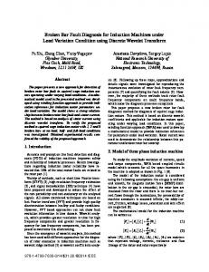
2 DFIG control system In this paper, the DFIG is assumed to be controlled with a stator voltage oriented vector control system. In this control system, there are two inner rotor current control loops of high bandwidth (hundreds of Hertz) and two outer control loops, one to control the stator active power (injected into the grid) and the other one to control the stator reactive power. To ensure a stable operation of the entire system, the bandwidth of the outer control loops is much lower than the bandwidth of the inner ones. Typical values for the bandwidth of the power control loops are in the range of a few Hertz. Fig. 1 shows a general overview of the DFIG control system, and it will serve as a basis for the analysis of the machine behavior under normal and faulty conditions as well as for the experimental tests carried out later on. 1
In a synchronous reference frame with the q-axis aligned with the stator voltages, and considering the stator currents having positive and negative sequence components denoted by the superscripts + and -, respectively, for a stator fault the following equations are obtained:
uqrc
Ps*
uqr* iqr
Ps
idr*
* s
Q
Qs
udr*
vqr*
αβ
udrc vdr* dq
*
vα r v*β r
Converter
iqr*
θr
idr dq
abc
iabcr
udqs
abc
idqs
dq
Ps = 3 vqs iqs+ + 3 vqs iqs− = Ps{dc} + ΔPs{2 f s } 2 2 + 3 3 Qs = vqs ids + vqs ids− = Qs{dc} + ΔQs{2 f s } . 2 2
θm θes uabcs
iabcs
3 Proposed diagnostic technique 3.1 Analysis of an ITSC fault in the stator windings A steady-state operation condition of a DFIG is considered. The stator windings of this generator are directly connected to the grid, while the rotor windings of the DFIG are fed by a back-to-back converter that controls the d and q rotor current components, in a synchronous reference frame. The grid voltages have a fixed amplitude, with a fundamental frequency of f s and the DFIG is running with a rotor slip s . When a stator fault appears in the stator windings of the DFIG, due to the resulting asymmetry, the stator currents will contain a positive and a negative sequence component, at frequencies of f s and − f s , respectively. The interaction of the negative-sequence component of the stator currents and the stator (grid) voltages of the generator will give rise to a new spectral component in both the stator active and reactive powers of the DFIG, at a frequency of 2 f s . This frequency is much higher than the bandwidth of the two power control loops, hence the reference rotor current components idr* and iqr* will be barely affected by the presence of this fault. On the other hand, on the rotor side of the generator, the negative sequence component of the stator currents will induce rotor voltages at a frequency of
f = ( 2 − s ) fs .
3.2 Analysis of an ITSC fault in the rotor windings
In case the DFIG develops a rotor fault, and in analogy to what happens in an induction motor, a primary fault-related spectral component will appear in all stator currents, at a frequency of f lsb = (1 − 2s ) f s .
(6)
The interaction of this stator current component with the fundamental component of the stator flux will originate torque oscillations in the generator at a frequency of 2sf s which, in turn, will create speed oscillations at the same frequency. These speed oscillations will give rise to the appearance of a second spectral component in the stator currents, at a frequency given by
(1)
Taking into account that a DFIG usually operates with a rotor slip in the range of −0.3 ≤ s ≤ 0.3 , and that the bandwidth of the current control loops will be higher than the frequency given by (1), the control loops of the rotor currents will be able to impose rotor currents almost without any spectral component at a frequency of f r− . In terms of control theory, the effects of the stator fault will be seen as a disturbance by the rotor control loops, and this disturbance will be highly rejected, given the high bandwidth of such control loops. The total active and reactive powers of the stator windings of the DFIG can be given, in any reference frame, by (2) and (3), respectively. Ps = 3 (vds ids + vqs iqs ) 2 3 Qs = (vqs ids − vds iqs ) . 2
(5)
The first terms on the second hand of (4)-(5) are dc quantities and represent the active and reactive powers injected by the DFIG into the grid. The second terms in the second hand of (4)-(5) are ac quantities with a frequency of 2 f s , and appear as a direct consequence of the stator fault, hence their identification in the spectra of the active and reactive powers can be used for the detection of stator faults in the generator. In theory, in the considered reference frame, the stator currents iqs− and ids− have the same amplitude, meaning that both the active and reactive powers could be used with the same effectiveness for the detection of the stator fault. However, it should be taken into account that the active power injected into the grid by a wind generator changes in a much wider range and in a faster way when compared to the reactive power. To apply standard signal processing techniques like the FFT, one should prefer to use quantities that are more constant in detriment of others that vary more often, being that the main reason why in this paper we advocate to use the spectrum analysis of the stator reactive power rather than the spectrum of the active power for fault diagnosis.
Fig. 1 Control system of the DFIG.
− r
(4)
f usb = (1 + 2s ) f s .
(7)
Due to the high inertia of the drive train associated to a wind generator, which includes the gearbox, rotor hub and rotor blades, these speed oscillations will be reduced and, consequently, the amplitude of the current spectral component given by (7) will be much smaller than the amplitude of the stator current component given by (6). It should be noted that the stator current components at frequencies given by (6) and (7), in a synchronous reference frame, appear as spectral components at frequencies of −2sf s ( i lsb ) and 2 sf s ( i usb ), respectively. Hence, in that reference
(2) (3)
2
frame, the stator active and reactive powers of the DFIG with a rotor fault will be given by Ps = 3 vqs iqs+ + 3 vqs ( iqsusb + iqslsb ) = Ps{dc} + ΔPs{|2 sf s |} 2 2
If there is a variation in the rotor reactive power, for a given average rotor slip and neglecting the rotor transient rotor inductance, the following relation will apply Now, the severity factors can be defined for both faults addressed in this work. For the case of a stator fault, a severity factor SFsf is defined as the ratio between the amplitude of the oscillating component in the stator reactive power at a frequency of 2 f s ( ΔQs{2 f s } ) and the rated stator reactive power of the DFIG ( Qsn = 3U sn I sn cos ϕ n ):
(9)
frequency of |2 sf s |
In this case, for very low values of the rotor slip, the oscillations in the stator active and reactive powers at a frequency of 2sf s , introduced by the rotor fault, will influence the outputs of the two PI power controllers, originating oscillations in the two reference rotor currents i dr* and i qr* at the same frequency. Hence, in the vicinity of the synchronous speed of the generator, any attempt to quantify the extension of the fault would have to take into account the influence of the control system on the behavior of the generator. The way how the control systems changes the effects of the rotor fault depends on the tuning of the PI power controllers and on some DFIG electric and mechanical parameters. A similar phenomenon has already been observed in the diagnosis of rotor faults in induction motors, as reported in some early studies [25]. This paper will not try to solve completely this issue, as it needs to be treated in detail in a separate and more comprehensive work. The results shown in (9) demonstrate that the rotor fault can be detected by the identification of a spectral component at a frequency of 2sf s in the total stator reactive power of the DFIG. A word of caution should be given: if the DFIG operates at exactly the synchronous speed, not only the quantification but also the possibility of detection of the rotor fault will be compromised. In that case, the detection of this type of fault needs to rely on second order effects, for instance on the use of the space harmonics created by the currents circulating in the stator and rotor windings.
SFsf (%) =
SFrf (%) =
Qr ≈ s ( K − Qs )
(11)
K=
3 ωsψ 2 Ls
2 ds
.
Qsn
× 100 .
(14)
ΔQs{|2 sf s |} × 100 . s × Qsn
(15)
4 Experimental setup In order to evaluate thoroughly the effectiveness of the proposed diagnostic technique, a DFIG experimental setup was built in the laboratory, as shown in Fig. 2. It includes a 4 kW wound rotor induction generator (WRIG) whose rotor windings are fed by a back-to-back converter, while its stator windings are directly connected to the grid. To emulate the wind turbine, the DFIG is mechanically coupled to an induction motor controlled by a variable speed drive. The details of the WRIG are listed in Table 1. The rotor side converter and generator are controlled with a stator voltage oriented vector control strategy [27]. The control system follows closely the diagram shown in Fig. 1 and was implemented in a dSPACE 1103 platform, where all quantities are measured and processed. Through a graphical interface, the user sets the reference values of the active power ( Ps* ) and reactive power ( Qs* ) injected into the grid by the DFIG (negative values mean that the power is flowing from the DFIG to the grid). The PI controllers of the control system were tuned using the Amplitude Optimum criterion. The bandwidth of the power control loops was set to 7.16 Hz, while the current control loops have a bandwidth of 324 Hz. The stator and rotor ITSC faults in the DFIG are emulated by connecting a variable resistor in parallel with one phase winding of the stator and rotor, respectively. The number of shorted coils/turns can be adjusted by changing the value of the variable resistor.
In the diagnosis of faults, it is important not only to be able to detect them but also to quantify their extension, that is, to determine how serious are those faults. This is the role played by the severity factors ( SFs ). Neglecting the copper losses, the stator and rotor active and reactive powers of a DFIG operating in steady-state and in healthy conditions, are given by (10) and (11), respectively [26, 27]: (10)
ΔQs{2 f s }
For the case of a rotor fault, the severity factor SFrf is defined by (15), where ΔQs{|2 sf s |} is the oscillating component in the stator reactive power at a frequency of 2sf s :
3.3 Definition of severity factors
Pr ≈ − sPs
(13)
(12)
Nameplate data Measured parameters Stator voltage 400 V Stator resistance 1.09 Stator current 8.49 A Rotor resistance 0.39 Rotor voltage 229 V Stator leakage inductance 8.20 mH Rotor current 11.5 A Rotor leakage inductance 2.93 mH Rated speed 1431 rpm Magnetization inductance 0.18 mH Pair of poles 2 Ratio of stator to rotor turns 1.68 Table 1 Parameters of the WRIG
In (10)-(12) Pr and Qr are the active and reactive powers injected into the rotor of the DFIG, respectively, ψ ds is the stator flux linkage, ωs = 2π f s is the angular supply frequency and Ls is the self-inductance of the stator windings. Since the stator voltages are imposed by the grid, K will be a constant value.
3
The stator reactive power of the DFIG for the two aforementioned DFIG operating conditions are shown in Fig. 5 and Fig. 6, respectively. When the reference value of the active power was set to 0 W, the stator currents of the DFIG are perfectly balanced, although they constitute a negative sequence component. This component is a direct consequence of the stator fault and in terms of stator reactive power, will originate a spectral component at a frequency of 100 Hz, as seen in Fig. 5. This result is important because it shows that any diagnostic method based on the measurement of the unbalance of the stator currents for the detection of this type of fault will fail, and will not give a correct indication about the condition of the generator. When the injected active power is increased to 1500 W, the currents become clearly unbalanced because now they have positive and negative sequence components, being the first the dominant one (Fig. 4(b)). As presented in Fig. 5(b) and Fig. 6(b), the stator reactive power gives us the indication of a stator fault by the presence of the spectral component at 100 Hz. Moreover, the amplitude of this spectral component, which is a measure of the extension of the stator fault, did not change significantly for these two operating conditions. Results obtained for other values of the injected active and reactive power demonstrate that the amplitude of that component is almost independent of the operating conditions of the DFIG. The evolution of the severity factor defined by (14), as a function of different generator operating conditions, namely, active and reactive powers injected into the grid and rotor speed is shown in Fig. 7. These results clearly show that this severity factor is highly independent of all operating conditions of the DFIG, thus constituting a good indicator about the extension of the fault or degree of asymmetry of the generator as far as the stator is concerned.
Ωm
θ enc
Ps*
Qs* Fig. 2 Schematic diagram of the experimental setup.
5 Experimental results The experimental tests were performed with the DFIG in healthy conditions and with stator and rotor inter-turn faults, for different values of the rotor speed (both at subsynchronous and supersynchronous mode of operation), as well as for different levels of the active and reactive power injected into the grid. 5.1 Healthy operation
1500 1000 500 0 -500 -1000 -1500 1
Stator currents [A] Stator currents [A]
QS [VAr]
The time waveform and the spectrum of the stator reactive power of the DFIG operating in healthy conditions, with a rotor speed of 1250 rpm, and when injecting 1500 W into the grid is shown in Fig. 3. It is clear that in healthy conditions the spectral components of the stator reactive power at the frequencies 2sf s (16.6 Hz) and 2 f s (100 Hz) are negligible, which is in the agreement with the fact that the DFIG has no faults. Similar results were obtained for other operating speeds and different values of the active and reactive power injected into the grid.
(a) 1.005
1.01
1.015
1.02
1.025
1.03
1.035
1.04
1.045
1.05
Time [sec]
QS [VAr]
1200 900 600 300 0 0
20
(b)
X=100 Y=35
X=16.6 Y=13
40
60
80
100
120
Frequency [Hz]
8
iA
4
iB
iC
(a)
0 -4 -8 8
iA
4
iB
iC
0
(b)
-4 -8 1
1.005
1.01
1.015
1.02
1.025
1.03
1.035
1.04
1.045
1.05
Time [sec]
Fig. 3 Stator reactive power of the DFIG in healthy conditions (n=1250 rpm, Ps* = −1500 W , Qs* = 0 VAr ): (a) time waveform; (b) spectrum.
Fig. 4 Stator currents of the DFIG with a stator fault (n=1250 rpm, Qs* = 0 VAr ): (a) Ps* = 0 W ; (b) Ps* = −1500 W . QS [VAr]
5.2 Stator fault
The results presented in this subsection were obtained for the DFIG operating with a stator fault and a rotor speed of 1250 rpm. The ITSC fault was emulated by connecting a resistor in parallel with phase A of the stator windings. The stator current waveforms of the DFIG for two different values of the active power injected into the grid (0 W and 1500 W) are shown in Fig. 4. In both cases, the reactive power was set to 0 VAr.
1500 1000 500 0 -500 -1000 -1500 1
(a) 1.005
1.01
1.015
1.02
1.025
1.03
1.035
1.04
1.045
1.05
Time [sec]
QS [VAr]
1200 X=100 Y=1051
900 600
(b)
300 0 0
20
40
60
80
100
120
Frequency [Hz]
Fig. 5 DFIG stator reactive power for a stator fault (n=1250 rpm, Ps* = 0 W , Qs* = 0 VAr ): (a) Time waveform; (b) FFT spectrum.
4
QS [VAr]
QS [VAr]
1500 1000 500 0 -500 -1000 -1500 1
(a) 1.005
1.01
1.015
1.02
1.025
1.03
1.035
1.04
1.045
1.05
1500 1000 500 0 -500 -1000 -1500 1
(a) 1.02
1.04
1.06
Time [sec]
1.12
1.14
1.16
1.18
1.2
1200 X=100 Y=1075
900 600
QS [VAr]
QS [VAr]
1.1
Time [sec]
1200
(b)
300 0 0
1.08
20
40
60
80
100
900 600 300 0 0
120
X=16.6 Y=297
20
Frequency [Hz]
(b) 40
60
80
100
120
Frequency [Hz]
Fig. 6 Stator reactive power of the DFIG with a stator fault (n=1250 rpm, Ps* = −1500 W , Qs* = 0 VAr ): (a) time waveform; (b) spectrum.
Fig. 8 DFIG stator reactive power operating with a rotor fault (n=1250 rpm, Ps* = −1500 W , Qs* = 0 VAr ): (a) time waveform; (b) spectrum.
(a)
(a)
(b)
(b)
(c)
(c)
Fig. 7 Severity factor for the operation of the DFIG with a stator fault, as a function of: (a) injected active power (n=1250 rpm, Qs* = 0 VAr ); (b) injected reactive power (n=1250 rpm, Ps* = −1000 W ); (c) rotor speed ( Ps* = −1500 W , Qs* = 0 VAr ).
Fig. 9 Evolution of the severity factor, defined for the rotor fault, with: (a) injected active power (n=1250 rpm, Qs* = 0 VAr ); (b) injected reactive power (n=1250 rpm, Ps* = −1000 W ); (c) rotor speed ( Ps* = −1500 W , Qs* = 0 VAr ).
5.3 Rotor fault
6 Conclusion
The ITSC fault was emulated in phase a of the rotor windings by using a resistor. Due to the lack of space available, only one situation will be documented in the paper, although several tests were conducted in the laboratory. Fig. 8 shows the time waveform and spectrum of the stator reactive power when the DFIG operates with a rotor fault and with n=1250 rpm, Ps* = −1500 W and Qs* = 0 VAr . It is clear that there is a spectral component related to the existence of the rotor fault at a frequency of |2sf| (16.6 Hz). The behavior of the severity factor defined in (15), for different operating conditions of the DFIG is shown in Fig. 9. The results show that this severity factor is almost independent of the values of active and reactive power injected into the grid. Nevertheless, the rotor speed (and consequently, the rotor slip), influences the obtained results, as stated before. The closer the rotor speed is of the synchronous speed, the minor are the effects of the rotor asymmetry in all stator quantities (currents, active power, reactive power, etc). Hence, in an actual wind generator, the diagnosis of a rotor fault, to be reliable, has to be performed when the generator is operating at a speed different and, preferably, far apart, the synchronous speed.
This paper proposes a new diagnostic method for the detection of ITSC faults in the stator and rotor windings of DFIGs, based on the FFT of the stator instantaneous reactive power. The obtained results show that ITSC faults in the stator windings can be reliably detected by the identification in the stator reactive power spectrum of a component at twice the fundamental stator frequency (2f). In case of an ITSC fault in the rotor windings of the DFIG, the spectral component appearing in the spectrum at twice the rotor frequency (|2sf|) is the main indicator of the fault. For each type of fault a severity factor was defined, and their behaviour was evaluated for different operating conditions of the DFIG. The obtained severity factors are highly independent to the different generator operating conditions, namely active and reactive power injected into the grid and rotor speed. Hence, they can be considered appropriate for the identification and quantification of the studied faults. The only exception is the ability of detecting a rotor fault in the vicinity of the synchronous speed of the machine that is an infrequent operating condition in real wind turbine systems. In that case, the fault may remain unnoticed until the generator operates at a speed different from that value. 5
Further research is currently ongoing in order to improve the applicability of this diagnostic approach, being scheduled the implementation of a pilot project in an actual wind generator.
[14]
Acknowledgements This research is supported by ENDIPREV Lda. (www.endiprev.com) and partially financed by the European Regional Development Fund (ERDF) under project number CENTRO-07-0202-FEDER-030277.
[15]
[16]
References [1] [2] [3] [4] [5]
[6]
[7]
[8]
[9]
[10]
[11] [12]
[13]
F. V. Hulle, N. Fichaux, A. F. Sinner, and P. E. Morthorst, Wind energy and the electricity grid, a report by the European wind energy association, 2010. P. Kühn, V. D. Brune, D. Callies, S. Faulstich, G. Füller, S. A. Lopez, P. Lyding, and R. Rothkegel, wind energy report Germany 2010, 2011: Kassel-Germany. L. M. Popa, B. B. Jensen, E. Ritchie, and I. Boldea, “Condition monitoring of wind generators,” in Proc. IAS. Salt Lake City, UT, USA, 2003. G. Gao and W. Chen, “Design challenges of wind turbine generators,” in Proc. EIC. Montreal, QC, 2009. Y. Amirat, M. E. H. Benbouzid, E. Al-Ahmar, B. Bensaker, and S. Turri, “A brief status on condition monitoring and fault diagnosis in wind energy conversion systems,” Renewable and Sustainable Energy Reviews. 13(9): p. 2629-2636, 2009. S. M. A. Cruz and A. J. M. Cardoso, “Stator winding fault diagnosis in three-phase synchronous and asynchronous motors, by the extended Park's vector approach,” IEEE Trans. Industry Applications. 37(5): p. 1227-1233, 2001. S. M. A. Cruz and A. J. M. Cardoso, “Multiple reference frames theory: a new method for the diagnosis of stator faults in three-phase induction motors,” IEEE Trans. Energy Conversion. 20(3): p. 611-619, 2005. J. Cusido, L. Romeral, J. A. Ortega, J. A. Rosero, and A. Garcia, “Fault detection in induction machines using power spectral density in wavelet decomposition,” IEEE Trans. Industrial Electronics. 55(2): p. 633-643, 2008. R. M. Tallam, L. Sang-Bin, G. C. Stone, G. B. Kliman, Y. Ji-Yoon, T. G. Habetler, and R. G. Harley, “A survey of methods for detection of stator-related faults in induction machines,” IEEE Trans. Industry Applications. 43(4): p. 920-933, 2007. A. Gandhi, T. Corrigan, and L. Parsa, “Recent advances in modeling and online detection of stator interturn faults in electrical motors,” IEEE Trans. Industrial Electronics. 58(5): p. 1564-1575, 2011. H. Douglas, P. Pillay, and P. Barendse, “The detection of interturn stator faults in doubly-fed induction generators,” in Proc. IAS. Kowloon, Hong Kong, 2005. D. Shah, S. Nandi, and P. Neti, “Stator-interturn-fault detection of doubly-fed induction generators using rotor-current and search-coil-voltage signature analysis,” IEEE Trans. Industry Applications. 45(5): p. 1831-1842, 2009. J. Zafar and J. Gyselinck, “CUSUM based fault detection of stator winding short circuits in doubly-fed
[17]
[18]
[19]
[20] [21]
[22]
[23]
[24]
[25] [26]
[27]
6
induction generator based wind energy conversion systems,” in Proc. ICREPQ. Granada, Spain, 2010. S. Toma, L. Capocchi, and G. A. Capolino, “Woundrotor induction generator inter-turn short-circuits diagnosis using a new digital neural network,” IEEE Trans. Industrial Electronics. 60(9): p. 4043-4052, 2013. Q. Lu, T. Breikin, and H. Wang, “Modelling and fault diagnosis of stator inter-turn short circuit in doubly-fed induction generators,” in Proc. IFAC. Milan, Italy, 2011. J.-q. Li, D. Wang, and L. He, “Study of rotor winding inter-turn short circuit fault in doubly fed induction generator based on current signal spectrum analysis,” in Proc. ICEMS. Busan, South Korea, 2013. V. Dinkhauser and F. W. Fuchs, “Rotor turn-to-turn fault detection in doubly-fed induction machines by means of state space modeling and Luenberger observer,” in Proc. SDEMPED. Cargese, France, 2009. A. Stefani, A. Yazidi, C. Rossi, F. Filippetti, D. Casadei, and G. A. Capolino, “Doubly-fed induction machines diagnosis based on signature analysis of rotor modulating signals,” IEEE Trans. Industry Applications. 44(6): p. 1711-1721, 2008. Y. Gritli, L. Zarri, C. Rossi, F. Filippetti, G. Capolino, and D. Casadei, “Advanced diagnosis of electrical faults in wound-rotor induction machines,” IEEE Trans. Industry Applications. 60(9): p. 4012-4024, 2013. S. Djurovic and S. Williamson, “Condition monitoring artefacts for detecting winding faults in wind turbine DFIGs,” in Proc. EWEC. Marseille, France, 2009. C. J. Crabtree, S. Djurovic, P. J. Tavner, and A. C. Smith, “Condition monitoring of a wind turbine DFIG by current or power analysis,” in Proc. PEMD. Brighton, UK, 2010. Y. Amirat, V. Choqueuse, M. E. H. Benbouzid, and J. F. Charpentier, “Bearing fault detection in DFIG-based wind turbines using the first Intrinsic Mode Function,” in Proc. ICEM. Rome, Italy, 2010. S. J. Watson, B. J. Xiang, Y. Wenxian, P. J. Tavner, and C. J. Crabtree, “Condition monitoring of the power output of wind turbine generators using wavelets,” IEEE Trans. Energy Conversion. 25(3): p. 715-721, 2010. M. Wurfel and W. Hofmann, “Monitoring of the transmission properties of the rotor slip ring system of doubly-fed induction generators,” in Proc. IEMDC. Texas, USA, 2005. S. M. A. Cruz and A. J. M. Cardoso, “Diagnosis of rotor faults in direct and indirect FOC induction motor drives,” in Proc. EPE. Aalborg, Denmark, 2007. G. Abad, J. Lopez, M. Rodriguez, L. Marroyo, and G. Iwanski, Doubly fed induction machine: modeling and control for wind energy generation: Wiley-IEEE Press. 2011. A. P. Gonçalves, “Control of the doubly-fed induction machine, for the study of the impact of power systems faults on the behavior of wind generators”, Master's thesis, in Department of Electrical and Computer Engineering, University of Coimbra, 2013.