Intuitive Robot Tasks with Augmented Reality and Virtual Obstacles Andre Gaschler, Maximilian Springer, Markus Rickert and Alois Knoll
Abstract— Today’s industrial robots require expert knowledge and are not profitable for small and medium sized enterprises with their small lot sizes. It is our strong belief that more intuitive robot programming in an augmented reality robot work cell can dramatically simplify re-programming and leverage robotics technology in short production cycles. In this paper, we present a novel augmented reality system for defining virtual obstacles, specifying tool positions, and specifying robot tasks. We evaluate the system in a user study and, more specifically, investigate the input of robot end-effector orientations in general.
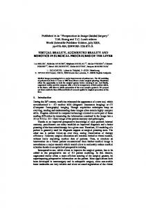
Monitor
Robot
3D input device
Start position
I. I NTRODUCTION Even though hardware costs dropped significantly over the past decades, industrial robots are still not profitable enough for small and medium sized enterprises (SMEs). Shraft et al. [1] identify three major objectives in order to leverage robotics technology in small scale production: reducing training times to a single day, simplifying changes and reprogramming, and dramatically reducing programming time as a whole. In contrast to large companies, SMEs typically face small lot sizes, short production cycles, unstructured environments, and do not employ experts with robotics knowledge. Programming a robot system with conventional interfaces is extremely time-consuming, difficult, and error-prone. With the advent of augmented reality (AR) and new interaction interfaces, we are able to visualize task plans and robot motions in the workspace of the human worker. With this, we improve users’ spatial perception and understanding of the robot’s capabilities, and, most importantly, allow users to give instructions to the robot in a more natural and intuitive way. In this work, we present and evaluate an intuitive robot system in an augmented reality work cell. The user is given a hand-held pointing device for specifying waypoints for the robot end-effector and for triggering corresponding actions. The system can handle generic types of robots, and is demonstrated with both typical six degrees-of-freedom (DOF) industrial manipulators and a human-like robot with a ten DOF. A top-mounted projector displays an augmented reality user interface on the work table. Coordinate systems of the work table and the robot can quickly be calibrated at initial setup. Additional obstacles in the work cell can be specified during interaction—inverse A. Gaschler, M. Springer and M. Rickert are with the fortiss GmbH affiliated to Technische Universit¨at M¨unchen, Munich, Germany. Correspondence should be addressed to
[email protected] A. Knoll is with the Department of Informatics, Technische Universit¨at M¨unchen, Munich, Germany.
Goal position
Obstacle
Overlay projection
Fig. 1. Intuitive robot system with augmented reality worktop overlay, 3D visualization, and a hand-held input device. A video is available in the file attachment of this paper and on the webpage http://youtu.be/ G-ZTeb-Si-s.
kinematics, collision detection, and path planning are used in order to generate a fast and collision-free robot trajectory. In a user study, we empirically investigate how robot postures can be defined using a hand-held 3D pointing device. Two different input modalities have been implemented and evaluated; the results of our study apply to the problem of specifying orientations with a hand-held input device in general. II. R ELATED W ORK Today’s relevant industrial programming techniques can roughly be classified into online and offline techniques [1]. Online programming takes place at the site of production itself and requires access to the robot and equipment. Popular online techniques are lead-through and walk-through programming. In lead-through programming, the robot’s control is set to a “teach” mode and a proprietary teach pendant (e.g. a joystick or a teachpad) is used to lead the robot through the desired sequence of events. Lead-through programming is generally time-consuming and unintuitive [2]. It is easy to imagine that adjusting a six degrees of freedom (DOF) robot arm with a two DOF joystick is not straightforward. Especially trajectory oriented tasks can be very time consuming to program with today’s complex teach pendants [2]. In walk-through programming, the human operator is in direct physical contact with the robot and moves the joints to the desired positions. Although this method allows intuitive robot programming, only few lightweight robots offer the necessary zero-torque control, and even then, safety concerns
may forbid operators to work in direct physical contact with the robot. Offline programming is the process of generating programs through simulation before execution on a real robot. Offline programming can reduce on-site programming time and downtime of manufacturing equipment. However, an accurate 3D model of the working environment is required, which is rarely available for the flexible manufacturing processes in small and medium sized enterprises. Even if simulation is successful, execution on the real robot often requires adjustments to the program [2]. Beyond these conventional methods, programming by demonstration (PbD) has recently gained research attention. Ideally, a programming by demonstration system will extract a robot program purely from human demonstration [3]. PbD has proved particularly useful with humanoid robots [3]. However, the problem of handling suboptimal demonstrations is subject to on-going research. All in all, methods of programming robots by demonstration or other natural human input, such as speech or gestures, generally lack the necessary robustness for industrial applications. Our central approach to facilitate robot programming is to both visualize robot motions and task plans, and allow 3D user inputs directly in the robot working cell by means of augmented reality (AR). A number of groups have applied augmented reality to ease robot programming, including recent contributions by Lambrecht and Kr¨uger [4], [5]. For visualization, most systems use head-mounted displays (HMD) [6], [7], [8] or video see-through (VST) displays [9], [2], [10] or hand-held see-through displays [4], [5]. Only Vogl’s group [9], [2] uses laser projection in their augmented reality work cell to highlight contours; we are the first to include the complete user interface in the overlay projection for spatial robot programming. From the systems above, most of them rely on via points to interpolate a robot path and do not take obstacles into account. Only two of the above systems allow the user to specify collision free volumes (CFV) [8], [10] and generate a path within these volumes. Even though CFV allow collision avoidance, they may be cumbersome to define and can be of complicated shape—if the defined CFV does not allow enough space from the start to the goal position, no path will be found. The system presented in this work is novel in that it allows intuitive robot path planning by defining a task scenario with obstacles and positions (in contrast to demonstration or direct trajectory input) in a worktop overlay projection augmented reality. III. I MPLEMENTATION Our intuitive robot path planning system is guided by three principles: Virtual obstacle are defined by simple geometric bodies users can specify with a 3D pointing device, robot postures are likewise defined in task space, and finally valid paths are automatically planned and executed. This procedure is also reflected in the user interface, which follows this sequence. The whole system is integrated in a robot workcell with an overlay video projection onto the worktop and
Fig. 2. Augmented reality worktop overlay projected on the work table. Visualized are the interface elements in the bottom corners, the current cursor projection, user defined obstacles, user defined end-effector positions, and a projected path. Projections on objects higher than the worktop plane are correctly modeled by projective geometry.
additional monitors for 3D views, as shown in Fig. 1. The overlay projection models projective geometry and respects the foreshortening of objects higher than the worktop plane. User input is given by a 3D pointing device that is tracked by a simple stereoscopic infrared motion capture system, which we made publicly available within the Track-it-Yourself library (TIY)1 . The motion capture algorithm used is described in [11] and documented in depth in [12]. Motion capture computations introduce only a minor delay in addition to image acquisition and visualization, summing up to a total delay of the user interaction of less than 30 ms. In the following, we elaborate the central processing steps of our intuitive task specification system: calibration, obstacle and end-effector input, and path planning. A. Projector and Robot Calibration Calibration is required in order to achieve an accurate projection for the mouse cursor, obstacles, and robot poses on the work table. Similarly, the robot coordinate system has to be calibrated towards the common world coordinate system defined by the table and its optical tracking markers. For calibration of the projector unit, we display a number of points on the work table. In order to find a matching world coordinate system representation, we point at each of them using the input device of the calibrated tracking system. In order to avoid degenerate configurations, the 3D coordinates of the projected points are measured at different heights. In order to calibrate the robot itself, the user can specify an arbitrary position on the table T tool table that can be reached by the manipulator. It is then marked with a projected cross and the user has to move the robot end-effector to this specified location in order to finish the mapping defined by T robot table = tool robot T robot T . Using multiple such measurements, T tool table table is obtained by least squares minimization. B. Obstacle Specification Rather than having the user define collision-free volumes, we rely on direct definition of obstacle regions in the robot’s 1 http://code.google.com/p/tiy/
Fig. 3. User specifies an end-effector orientation for a six DOF industrial manipulator. The visualization of the robot is constantly updated to give a preview of kinematic reachability and collision detection.
workspace. Our underlying idea is to make the robot task definition given by the user completely constraint-based. Obstacles define regions that the robot must not collide with and robot postures are purely defined in the task space. This constraint-based principle enables—in theory—intuitive robot programming that is independent of the specific properties of the robot. Furthermore, obstacles need not necessarily be physical objects in the robot workspace. In order to limit the robot’s motion, the user is free to define virtual obstacles, which are visualized on the worktop and on additional desktop monitors. A user can thus restrict the robot from moving into undesired areas in the work cell. As the goal of obstacle definition is to allow collision-free path planning, it is usually not necessary to specify the exact boundaries of complicated, possibly concave bodies. It is rather practical to specify “obstacle regions” that completely enclose the obstacles. Specifying obstacle regions, rather than accurate shapes, of obstacles makes the specification procedure much more intuitive and easier for the user. To further facilitate the process, we chose a right prism as the default geometric body to specify such a region. A right prism is a geometric body with an n-sided polygonal base and n-side edges which are of equal length, parallel and normal to the base face. To define such a right prism, the user sets the n corners of the upper face of the prism. Since the user will not be able to specify n points which all exactly lie in one plane, the z-coordinate of the highest point is used for all points as a conservative estimate. This guarantees that the specified surface is a polygon in a plane parallel to the workspace table plane and all specified points are inside the volume of the prism. While specifying obstacle regions, the user constantly receives visual feedback. The lines connecting the set points are displayed in a 3D view on the monitor and as an orthographic projection directly on the table. Furthermore, obstacle regions may be selected by 3D input for editing or deletion. C. End-Effector Position Specification Besides obstacles, robot postures are needed to define waypoints along the desired motion path. Setting individual joint angles would be tedious and unintuitive, therefore the
augmented robot workcell allows the user to define endeffector poses directly in the 3D workspace. This concept follows the constraint-based principle and allows the task to be defined independent of the robot’s properties. An end-effector pose consists of a position and an orientation in 3D space. One way to indicate these would be to directly use the position and orientation of the input device as the pose of the end effector. This simple solution however has several shortcomings: First, given the anatomy of the human arm, many orientations are impossible to reach or can only be defined rather imprecisely. Second, when using an optical tracking system, optical markers are often occluded by the human operator or the input device itself. Specifying positions in 3D space is not affected by these limitations, as the probe can always be held at a comfortable orientation. For these reasons, the robot tool frame specification is split into two steps, first specifying the end-effector’s position and then its orientation. Even though it is obvious how to indicate a 3D position with a hand-held pointing device, indicating an orientation is an interesting problem. To the best of the authors’ knowledge, it is not yet been investigated which method is the most intuitive to specify a robot end-effector pose given a 3D pointing device. In our user study, we compared two such methods with respect to objective task completion and subjective rating, which are further elaborated in Section III-D. Robot tool frame specification is completely interactive: While moving the pointing device, inverse kinematics calculation is performed online and a robot configuration fulfilling all given constraints is visualized. Simultaneously, the robot configuration is checked for collisions [13] and colliding bodies of the kinematic chain are highlighted in red. D. End-Effector Orientation Specification As mentioned above, directly using the orientation of the input device as an orientation for the end effector is problematic. In this work, we investigated two different methods to specify an end-effector orientation with a tracked, hand-held pointing device. As these two orientation input methods are studied in the evaluation in Section IV, we explain these procedures in detail. a) Relative Mode: In this mode, the orientation is changed by rotating the input device. As long as a button on the input device is pressed, the relative rotation of the input device is applied to the end-effector. When the button is first pressed, the current rotation of the input device is stored as a reference. While the button is pressed and the input device is rotated, the relative rotation with respect to the stored starting rotation is computed. This relative rotation is then applied to the current rotation of the end effector. After the button is released, the rotation of the input device has no effect on the end effector anymore. This way, large end-effector rotations can be achieved by applying multiple small consecutive rotations. b) Two Axes Mode: In the two axes mode, the orientation is set by specifying two axes. The first axis determines the direction in which the end-effector points, which is
Fig. 4. Robot end-effector orientation specification by two axes: First, the direction of the z-axis is defined a by point on that axis (left). Then, the rotation around that axis is defined by point on the x-axis (right).
defined as the end-effector z-axis (s. Fig. 4 left). The second axis, or end-effector x-axis, determines how the end effector is rotated around the first axis (Fig. 4 right). In user interaction, an axis is determined by two points in space. To specify the first axis, the user moves the input device to a point in space which should lie on the axis and presses the button once. For the second point that is required to define the axis, the previously set end-effector position is used. The second axis determines the rotation of the end-effector around the first axis, and must therefore be perpendicular to the first. To achieve this, input device position is orthogonally projected onto the plane that includes the end-effector position and is orthogonal to the z-axis. During all system interactions, the user receives immediate visual feedback. While moving the input device to define positions and orientations, all geometric and inverse kinematics calculations are performed in real-time. All points and axes that are being defined are highlighted, and the virtual end effector is visualized in a pose that complies with constraints that are being set. More detailed information on the implementation can be found in [14]. During interaction, the system aims to avoid singularities and joint limits. The distance to singularities is calculated using the manipulability measure [15]. Using null space calculation [16], the joint velocity vector is optimized in a way to move the robot posture away from singularities. Joint limits are enforced applying a cost function that penalizes joint angles close to or beyond joint limits. For the humanoid robot with its redundant kinematics, the user is allowed to alter the “elbow” position of the robot by dragging it to a desired position. The end-effector frame is not affected by this manual posture optimization due to null space calculations. E. Collision-Free Path Planning The robot manipulator description includes both a kinematics specification and a geometry model. During the input of the end-effector’s waypoints, a matching configuration for the robot manipulator is generated via inverse kinematics calculation and validated against collision with itself and known obstacles. In the next step, the system needs to generate a collision-free path between each specified waypoint. Path planning for robot manipulators is a common problem in the robotics domain and several planning algorithms have been developed and studied [17]. Probabilistic Roadmaps (PRM) [18] and Rapidly-Exploring Random
Fig. 5. Visualization of collision free motion after successful path generation and optimization with a six DOF industrial manipulator.
Trees (RRT) [19] are common examples for sampling-based approaches in the robot’s configuration space. Due to the random nature of these planners, they often require additional path smoothing in order to create high-quality paths [20]. Given the basic nature of our environment, we have opted to use a RRT variant with two trees and an RRT-connect step as planning component together with a shortcut postoptimization step2 . The position of the sampled end-effector frames are visualized during planning and optimization, and are displayed with gray lines, while the solution path is displayed in green. IV. E VALUATION In order to evaluate our approach, we conducted a user study, both to evaluate the overall performance of the implemented system, and to compare two methods for specifying robot end-effector orientations. The problem of specifying rotations and orientations arises in many applications, such as in computer-aided design (CAD) programs. Usually, such programs are controlled with a two DOF mouse and/or a three DOF trackball and it has been well studied how rotations can be specified in such setups [21]. Literature research did not lead to any previous work on how object rotations can intuitively be set using an optically tracked six DOF input device. In our work, we implemented and evaluated the two methods for rotation specification “relative mode” and a “two axes mode”. The design of the user study and its results are presented in the following. A. Experiment Design As part of the goal of the experiment was to compare two input methods, we designed a task which the participants had to perform twice, once with each method. A detailed description of the experiment procedure can be found in the thesis by Springer [14]. In short, the experiment was organized as follows: The participants were asked to read a short description of the task they had to perform, including obstacle specification, and setting start and goal robot tool 2 http://www.roboticslibrary.org/
TABLE I O BJECTIVE RESULTS OF THE TWO ORIENTATION INPUT METHODS
Measurement
Input Mode
Mean Std Dev
Min
Max
Time to completion [s]
Relative Two Axes
65.2 31.9 129.5 87.4
22 33
150 370
No. of poses set
Relative Two Axes
2.4 3.4
0.81 1.3
2 2
5 6
Total input device translation [m]
Relative Two Axes
13.0 19.4
9.2 12.7
3.9 4.2
39.6 45.3
poses in the scenario. Then, participants were asked to fill in a short general questionnaire asking for age, gender, and level of robotics knowledge (with the option not to answer). The main experiment was divided into two phases, with our AR system configured in one of the two input methods “relative mode” and “two axes mode” for each phase. The order of the two input methods was randomized by alternating the order of the phases for each participant. At the beginning of each phase, the user interface was explained and demonstrated, including hands-on training. The participants could ask arbitrary questions and practice with the system for up to total training time of five minutes. Afterwards, participants were asked to perform the actual task in a simple scenario, as depicted in Figure 1: Pliers were attached to the end-effector of the robot, two boxes and one small drawer were put on the workspace table, and a bolt was placed on top of one of the boxes. The goal of the task was to make the pliers move to a position over the bolt, as if to pick up the bolt (the pliers were not actuated). The end-effector then had to move over to the small drawer in a position that would allow the robot to drop off the bolt. After participants could generate a valid path with the system, they were asked to fill out a short questionnaire asking for their subjective feelings about intuitiveness, accuracy, and speed of the system on a 5-point Likert scale. This phase was repeated with the system configured using the second input method. Finally, participants answered a general questionnaire asking for their preferred input method, ideas for improvement, and general comments. B. User Study Results 22 participants (17 male) took part in the user study, with age ranging from 22 to 47 years, most of them students of the computer science department. Their level of familiarity with robotics was mixed, with 41% having used a teach pendant for robot programming before. The latter were asked additional questions to compare our system with conventional teach pendants. All participants were able to complete the tasks without intervention. Objective Results: The time participants needed for specifying robot end-effector poses was measured in order to compare the two input methods (Table I). For the relative mode, the average required time was 65 seconds with a standard deviation of 32 seconds. Using the two axes mode,
the participants required 130 seconds on average with a standard deviation of 87 seconds. As these data are probably not normally distributed (which was tested with the ShapiroWilk test), we applied the Wilcoxon-Mann-Whitney test [22]. With this, we verified at a significance level of p < 0.01 that the relative mode takes less time than the two axes mode. When specifying the start and goal end-effector poses, participants were free to discard and repeat to set a pose until they were satisfied. With the relative mode, 2.4 poses were set on average, while 3.4 poses were set on average with the two axes mode. Again applying the Wilcoxon-MannWhitney test, we showed (p = 0.005) that users need to set less poses when using the relative mode. Subjective Results: The overall results of the subjective questionnaire answers match the objective results, with 18 participants preferring the relative mode and only four preferring the two axes mode. We showed this difference to be significant with p = 0.002 using a binomial test. In addition, we checked for a correlation between the level of familiarity with robotics and the preferred input method. However, we were not able to reject the independence of the “level of familiary” to the preferred input method on a 5% significance level using Fisher’s exact test. Furthermore, we analyzed the questionnaire of participants’ feelings about both input methods, given by their level of agreement about 8 statements on a five-point Likert scale. Each of the statements falls in one of three categories: speed, intuitiveness, and accuracy. We used the PARADISE procedure [23] to generate an iterative, stepwise multiple linear regression that predicts the subjective survey results based on the objective measures (task completion time, movement distance, and number of poses set) and the participant’s robotics knowledge (as given by the questionnaire). The generated predictor functions have the linear form w0 + P n i=1 wi · N (mi ), with mi representing the predictive measures. The function N transforms each predictive measure (task completion time, movement distance, number of poses set, and robotics knowledge) into a normal distribution using z-score normalization. The coefficients wi are computed through stepwise linear regression, and describe the relative contribution of each predictor to the subjective result. The resulting predictor functions are shown in Table II: Only the factors “task completion time” (time) and “robotics knowledge” (knowledge) are found to have a significant effect on the model. The R2 value indicates the percentage of the variance explained by the predictor function. A higher R2 value therefore means that future outcomes are more likely to be correctly predicted by the model. The p-value in the column “Significance” indicate the probability of a coefficient being not significant; we included all coefficients with p < 0.1. As a result, higher time to completion has a significant negative influence on the perceived quality of the system in all three categories. Besides that, a greater level of robotics knowledge has a significant positive influence on the perceived factors intuitiveness and accuracy.
TABLE II P REDICTOR FUNCTIONS FOR EACH CATEGORY ON THE QUESTIONNAIRE
Category
Predictor Function
R2
Significance
Intuitiveness Accuracy Speed
11.51 − 1.31 ∗ N (time) + 0.69 ∗ N (knowledge) 15.14 − 1.63 ∗ N (time) + 0.91 ∗ N (knowledge) 3.72 − 0.62 ∗ N (time)
0.27 0.33 0.35
time: p < 0.001, knowledge: p < 0.1 time: p < 0.001, knowledge: p < 0.05 time: p < 0.001
From the general questionnaire, we could find that 18 of the 22 participants find the input device intuitive to use (12 “agree” and 6 “strongly agree”). Considering the different steps of our robot programming approach, 21 of 22 found the obstacle definition intuitive (15 of them “strongly agree”), and 15 of 22 found the path planning accurate. Of the nine participants that have programmed a robot with a teachpad before, all agree that our system is easier to use than a teachpad. Considering free text comments, 9 participants positively mentioned the system’s intuitiveness. Criticism included the limited accuracy of the robot (caused by an imperfect calibration between robot and tracking system), the robustness of the tracking system, and lacking feedback why inverse kinematics fails. While our users’ comments indicate some space for improvement in the robot–projector calibration and the robustness tracking the input device, these points are rather due to easily remedied technical issues and not due to the general approach. V. C ONCLUSION AND F UTURE W ORK The overall results of our user study are very encouraging and indicate that our augmented reality approach is a promising method for intuitive robot programming. Considering the more specific research question how 3D orientations can be specified with a hand-held 6D input device, results clearly indicate the relative mode to be superior over the two axes mode (concerning speed and subjective accuracy and intuitiveness), as defined in Section III-D. Future work may include several technical improvements on input device tracking and calibration, as well as an indepth user study on the general problem how to input robot end-effector poses. VI. ACKNOWLEDGMENTS This research was supported by the European Union’s Seventh Framework Programme through the projects JAMES under grant agreement no. 270435 3 and SMErobotics under grant agreement no. 287787 4 . R EFERENCES [1] R. Schraft and C. Meyer, “The need for an intuitive teaching method for small and medium enterprises,” VDI Berichte, vol. 1956, p. 95, 2006. [2] G. Reinhart, U. Munzert, and W. Vogl, “A programming system for robot-based remote-laser-welding with conventional optics,” CIRP Annals-Manufacturing Technology, vol. 57, no. 1, pp. 37–40, 2008. 3 http://www.james-project.eu/ 4 http://www.smerobotics.org/
[3] R. Zollner, T. Asfour, and R. Dillmann, “Programming by demonstration: Dual-arm manipulation tasks for humanoid robots,” in Intelligent Robots and Systems. IEEE/RSJ Intl Conf on, vol. 1, 2004, pp. 479–484. [4] J. Lambrecht and J. Kr¨uger, “Spatial programming for industrial robots based on gestures and augmented reality,” in Intelligent Robots and Systems (IROS), IEEE/RSJ Intl Conf on, 2012, pp. 466–472. [5] J. Lambrecht, M. Kleinsorge, M. Rosenstrauch, and J. Kr¨uger, “Spatial programming for industrial robots through task demonstration,” Int J Adv Robotic Sy, vol. 10, no. 254, 2013. [6] T. Pettersen, J. Pretlove, C. Skourup, T. Engedal, and T. Lkstad, “Augmented reality for programming industrial robots,” in Proc Int Symposium on Mixed and Augmented Reality, 2003, p. 319. [7] S. Green, J. Chase, X. Chen, and M. Billinghurst, “Evaluating the augmented reality human-robot collaboration system,” International journal of intelligent systems technologies and applications, vol. 8, no. 1, pp. 130–143, 2010. [8] J. Chong, S. Ong, A. Nee, and K. Youcef-Youmi, “Robot programming using augmented reality: An interactive method for planning collisionfree paths,” Robotics and Computer-Integrated Manufacturing, vol. 25, no. 3, pp. 689–701, 2009. [9] M. Z¨ah and W. Vogl, “Interactive laser-projection for programming industrial robots,” in 5th IEEE and ACM International Symposium on Mixed and Augmented Reality, 2006, pp. 125–128. [10] H. Fang, S. Ong, and A. Nee, “Interactive robot trajectory planning and simulation using augmented reality,” Robotics and ComputerIntegrated Manufacturing, 2011. [11] A. Gaschler, “Visual motion capturing for kinematic model estimation of a humanoid robot,” in Pattern Recognition, 33rd DAGM Symposium, ser. Lecture Notes in Computer Science, vol. 6835, Sept. 2011, pp. 438–443. [12] ——, “Real-time marker-based motion tracking: Application to kinematic model estimation of a humanoid robot,” Master’s thesis, Technische Universit¨at M¨unchen, Munich, Germany, Feb. 2011. [13] G. van den Bergen, Collision Detection in Interactive 3D Environments, ser. The Morgan Kaufmann Series in Interactive 3D Technology. San Francisco, CA, USA: Morgan Kaufmann Publishers, 2004. [14] M. Springer, “An augmented reality based system for intuitive robot programming,” Master’s thesis, Technische Universit¨at M¨unchen, Munich, Germany, Nov. 2012. [15] T. Yoshikawa, “Manipulability of robotic mechanisms,” The International Journal of Robotics Research, vol. 4, no. 2, pp. 3–9, June 1985. [16] O. Khatib, “A unified approach for motion and force control of robot manipulators: The operational space formulation,” IEEE Journal of Robotics and Automation, vol. 3, no. 1, pp. 43–53, Feb. 1987. [17] S. M. LaValle, Planning Algorithms. Cambridge Univ Press, 2006. ˇ [18] L. E. Kavraki, P. Svestka, J.-C. Latombe, and M. H. Overmars, “Probabilistic roadmaps for path planning in high-dimensional configuration spaces,” IEEE Transactions on Robotics and Automation, vol. 12, no. 4, pp. 566–580, Aug. 1996. [19] J. J. Kuffner, Jr. and S. M. LaValle, “RRT-connect: An efficient approach to single-query path planning,” in IEEE International Conference on Robotics and Automation, Apr. 2000, pp. 995–1001. [20] R. Geraerts and M. Overmars, “Creating high-quality paths for motion planning,” Robotics Research, vol. 26, no. 8, pp. 845–863, Aug. 2007. [21] M. J. Van Emmerik, “A direct manipulation technique for specifying 3d object transformations with a 2d input device,” in Computer Graphics Forum, vol. 9, no. 4, 1990, pp. 355–361. [22] P. Teetor, R Cookbook. O’Reilly Media, Incorporated, 2011. [23] M. Walker, C. Kamm, and D. Litman, “Towards developing general models of usability with paradise,” Natural Language Engineering, vol. 6, no. 3 & 4, pp. 363–377, 2000.