This is the author's version of an article that has been published in this journal. Changes were made to this version by the publisher prior to publication. The final version of record is available athttp://dx.doi.org/10.1109/TCOMM.2015.2424241 IEEE TRANSACTIONS ON COMMUNICATIONS
1
Iterative Cancellation of Non-linear Distortion Noise in Digital Communication Systems Svilen Dimitrov
Abstract—In this paper, an iterative receiver that performs non-linear distortion noise cancellation is presented. The performance is assessed for time division multiple access (TDMA), orthogonal frequency division multiple access (OFDMA) and single-carrier frequency division multiple access (SC-FDMA) waveforms. Even though a return link setup is considered, the receiver is equally applicable in the forward link, taking into account the differences in the data multiplexing and the channel. Analytical modeling of the received electrical signal-to-noise ratio (SNR) is carried out for OFDMA with one iteration of non-linear distortion noise cancellation. The performance is assessed in terms of power efficiency and spectral efficiency, where the total degradation (TD) of the received SNR in a non-linear channel is minimized. The modulation formats of the DVB-RCS2 satellite return link standard and a respective non-linear channel have been used. OFDMA shows the highest power efficiency gain of 1.1 − 2.5 dB with 2 iterations of non-linear noise cancellation across the different modulation orders. In SC-FDMA, the gain is in the range of 0.3 − 1.1 dB, while gains of 0.1 − 0.8 dB and 0.2 − 1.9 dB are presented in TDMA with 20% roll-off and 5% roll-off, respectively. Index Terms—Non-linear distortion, OFDMA, SC-FDMA, TDMA, power efficiency.
I. I NTRODUCTION Nowadays, broadband access is considered a commodity. In order to provide coverage to all households on the territory of the European Union and Turkey, the project on Broadband Access via Integrated Terrestrial and Satellite Systems (BATS) [1] develops an integrated network solution, merging the benefits of terrestrial mobile networks, digital subscriber line (DSL) networks and satellite communication systems. In particular, intelligent network and user gateways are designed which can classify the traffic of different types of applications and route it via low-latency terrestrial networks or high-bandwidth satellite links to maximize the quality of experience. Due to the ongoing shift towards more bandwidth demanding applications and services, next generation networks need to offer higher system throughput and user data rates, flexibility to adapt to traffic demand across the coverage area, and at the same time decrease the cost per transmitted bit. For this purpose, a higher spectral efficiency without a significant increase in the computational complexity of the air interface is imperative. The utilization of larger pieces of bandwidth in the higher frequency bands, such as Ka, Q and V radio frequency (RF) bands, imposes significant hardware implementation challenges, and imperfections cause signal distortion. Therefore, suitable signal processing techniques at the transmitter or This work was supported by the BATS research project which is funded by the European Union Seventh Framework Programme under contract n317533. S.Dimitrov is with the German Aerospace Center (DLR), Satellite Networks Department, 82234 Wessling, Germany (e-mail:
[email protected]).
receiver side that maximize the information rate of the link are still an open issue. For example, communication over the satellite channel suffers from linear and non-linear distortion. The linear distortion is attributed to mismatch of the signal spectrum and the spectral response of the filters along the chain, while the non-linear distortion originates from the non-linear transfer characteristic of the high-power amplifiers (HPAs) onboard the satellite and at the user terminal. These adverse effects reduce the power and spectral efficiencies of the transmission waveform. Time division multiplexing (TDM) is the waveform of choice in the latest DVB-S2X [2] standard for the satellite forward link, while TDMA is employed in the return satellite link according to the DVB-RCS2 standard [3]. Waveforms such as OFDMA and SC-FDMA are at the heart of terrestrial mobile long-term evolution (LTE) networks due to their high spectral efficiency and flexible traffic allocation. These waveforms have also been recently considered for application over satellite for the sake of vertical network handover [1]. The performance of TDM for the forward satellite link has been studied in [4]. In addition, SC-FDMA and OFDMA have been compared for the return satellite link for amplifier characteristics in the K and S bands in [5]. In this study, a novel receiver is developed that performs iterative cancellation of the intermodulation interference (IMI) from the non-linear distortion, and it is tested for practical amplifier characteristics in Ka band with TDMA, OFDMA and SCFDMA waveforms. The aim of state-of-the-art communication systems to achieve higher data rates and throughput, and at the same time to use low cost consumer devices, results in the increase of the interference levels in the physical layer. The application of wideband signals in channels with insufficient coherence bandwidth due to frequency selectivity or dispersion results in inter-symbol interference (ISI). Similar effects are introduced also by imperfections in the frequency responses of the filters employed along the transmission chain. In addition, non-linear distortion effects, such as IMI, are introduced by the non-linear transfer characteristics of HPAs. In state-of-the-art systems, a common approach to handle the ISI is equalization [6], where the knowledge of the channel, obtained for instance by channel estimation, is used to counter the ISI. The IMI is handled by means of power control, such as input and output back-off (OBO) [4, 5]. This approach is known to penalize the power efficiency of the system when high OBO is applied. In state-ofthe-art systems, signal detection is performed in the presence of the interfering component and the additive white Gaussian noise (AWGN). A major shortcoming is that no measure is taken to extract the information carried in the interfering component, since the interference is treated as an additional
Copyright (c) 2015 IEEE. Personal use is permitted. For any other purposes, permission must be obtained from the IEEE by emailing
[email protected].
This is the author's version of an article that has been published in this journal. Changes were made to this version by the publisher prior to publication. The final version of record is available athttp://dx.doi.org/10.1109/TCOMM.2015.2424241 2
component to the noise. However, the transfer characteristics of the non-linear devices in the system are generally well known and easily obtainable through measurements. Therefore, the knowledge of the mechanisms causing the IMI can be used for interference cancellation. Cancellation of the IMI has been first proposed in [7] for OFDMA systems with an extension for coded OFDMA signals in [8]. The approach has been adopted for SC-FDMA in [9, 10]. The interfering component is estimated by means of a model for the received constellation centroids based on the Bussgang decomposition [11], where the attenuation of the transmitted symbols in the channel is exploited. In the estimation of the interfering component, a single attenuation factor is used for all the symbols in the constellation. This approach is applicable in systems, where the non-linear distortion noise is uncorrelated with the symbols, such as in OFDMA. However, when the IMI is correlated with the signal, such as in SC-FDMA and TDMA, individual scaling factors for each constellation point need to be computed. In this paper, an improved receiver design is proposed. The received constellation centroids are individually estimated and used for maximum likelihood (ML) signal detection. In addition, individual scaling factors are applied to the detected symbols, in order to improve the estimation procedure for the the interfering component in systems such as SC-FDMA and TDMA. The improved estimate is iteratively re-estimated and subtracted from the signal for the sake of an improved bit error rate (BER). In general, only a few iterations are sufficient to significantly improve the performance of the receiver, resulting in an increased power and spectral efficiency. The performance of this receiver is compared with static data predistortion at the transmitter [6, 12] which is used in state-ofthe art systems as a nonlinearity compensation technique. In addition, an analytical model for the received SNR and TD is developed and validated for OFDMA with one iteration of IMI cancellation. In [13], a model is presented for an optical system with a soft limiter amplifier with ideal clipping for a 16-quadrature-amplitude-modulation-(QAM) constellation. In this paper, a general model is developed which is applicable to any non-linear transfer characteristic and any constellation of a digital modulation scheme in an RF OFDMA system. The improved receiver enables operation with optimum TD at a much lower OBO, providing significant gains in the power efficiency. In the considered modulation setup, gains of up to 2.5 dB are expected for OFDMA, 1.1 dB for SC-FDMA, 0.8 dB for TDMA with 20% roll-off and 1.9 dB for TDMA with 5% roll-off. The gains of IMI cancellation are shown to increase for higher order modulations due to their higher sensitivity to non-linear distortion. The rest of the paper is organized as follows. Section II describes the setup of the TDMA, SC-FDMA and OFDMA digital transmission schemes. Section III presents the iterative receiver for IMI cancellation, including the non-linear effects, analytical modeling and validation. Section IV elaborates on the performance evaluation results. Finally, Section V concludes the paper.
IEEE TRANSACTIONS ON COMMUNICATIONS
II. D IGITAL TRANSMISSION SCHEMES Commercial digital communication systems include mobile wireless communications, DSL and cable communications, satellite communications and optical wireless communications such as infrared and visible light communications (VLC). In a digital transmission scheme, a stream of bits are mapped to information symbols from a given constellation at the modulator. In order to provide protection from the impairments in the channel, the bits can be encoded by a forward error correction (FEC) code. Common modulation formats include pulse amplitude modulation (PAM), pulse position modulation (PPM), QAM, phase shift keying (PSK), amplitude and phase shift keying (APSK), etc. It is assumed that the receiver knows the modulation order on the received symbols for every user through information in the frame preamble or control channel information. The modulated symbols are multiplexed in accordance with the underlying transmission format. TDMA is the common transmission format in satellite and ethernet communications, while frequency division multiple access (FDMA), such as OFDMA and SC-FDMA are used in the fourth generation (4G) LTE mobile wireless communications. In addition, SC-FDMA has been proposed as an option in the DVB-RCS2 satellite return link standard [3], due to its moderate peak-to-average-power ratio (PAPR) and high spectral efficiency. In TDMA, the sequence of symbols dedicated to different users in the system are time multiplexed. In OFDMA, the signal bandwidth is split in N orthogonal subcarriers, resulting in a high spectral efficiency. The inverse fast Fourier transform (IFFT) and the FFT are employed as multiplexing and demultiplexing techniques at the transmitter and the receiver, respectively. Due to the commonly applied cyclic prefix (CP), multi-path fading effects in the form of ISI, as well as multiple access interference (MAI), are mitigated, reducing the equalization effort to a single-tap equalizer. The multiple access is realized by assigning a number of subcarriers to a user. The assignment can follow a localized allocation in the form of subbands or an interleaved allocation. In SC-FDMA, the frequency domain symbols are pre-coded by means of a npoint FFT. After subcarrier mapping, a N -point IFFT (N > n) is used for multiplexing, and a CP is inserted. The multiple access realizations of SC-FDMA are commonly known as localized FDMA (LFDMA) and interleaved FDMA (IFDMA). Since the analog IFDMA and LFDMA signals exhibit similar PAPR [14], the focus in this study falls on LFDMA, due to its better applicability with synchronization techniques. After symbol multiplexing according to the transmission format, the information symbols are pulse shaped by means of a square root raised cosine filter (SRRCF) to ensure signal and spectrum integrity for RF transmission. In optical communication systems with intensity modulation and direct detection (IM/DD), this digital pulse shaping block is generally omitted due to the unipolar signal constraint. Next, the signal is passed through a digital-to-analog converter (DAC) and possibly through a transmit filter, e.g. during up-conversion to the carrier frequency. The transmitter device can introduce non-linear distortion, due to the non-linear transfer function
Copyright (c) 2015 IEEE. Personal use is permitted. For any other purposes, permission must be obtained from the IEEE by emailing
[email protected].
This is the author's version of an article that has been published in this journal. Changes were made to this version by the publisher prior to publication. The final version of record is available athttp://dx.doi.org/10.1109/TCOMM.2015.2424241 SUBMITTED PAPER
3
of the HPA in RF systems or the light emitting diode (LED) or laser diode (LD) in optical systems. This distortion is particularly prominent with amplitude modulated signals. Here, the distortion is described through a generalized non-linear transfer function, F (·). The signal is then passed through the channel. The channel can be RF wired, RF wireless, optical fibre or optical wireless, and it is characterized by its impulse and frequency responses. Multi-path effects in terrestrial communication channels introduce a linear distortion such as ISI. Similar effects are also introduced by the imperfect frequency responses of the filters along the transmission chain. In this study, it is assumed that the channel effect can be compensated by means of sufficiently frequent channel estimation and equalization at the receiver. In general, the channel can be a cascade of linear and non-linear devices as in relay systems with amplify and forward operation, such as in satellite communications. Without loss of generality, the signal at the receiver can be expressed as h ∗ F (x), where h is the cumulative impulse response, F (·) is the cumulative non-linear transfer function, and ∗ is the linear convolution operator. At the receiver, the signal is distorted by AWGN, w. As a result, the received signal, y, can be expressed as follows: y = h ∗ F (x) + w.
(1)
The receiver can include a receive filter, e.g. during downconversion back to baseband. The signal is then passed through an analog-to-digital converter (ADC) and a matched SRRCF is applied. In optical systems, the digital matched filter is generally omitted, if no pulse shaping filter is applied at the transmitter. The transmitter and receiver are assumed to be fine synchronized. This assumption is shown to be valid even in demanding applications such as synchronization over satellite. Suitable synchronization acquisition and tracking algorithms have been proposed in [15] to maintain the fine synchronization of the transmitted and received signals. Next, an equalizer is applied to counter the channel effect and the linear distortion. Here, zero forcing (ZF) or minimum mean squared error (MMSE) criteria are generally applied. The symbols are then demultiplexed, demodulated and decoded, to obtain the received bits.
generally correlated with the transmitted symbols. Therefore, each constellation point at the receiver can be individually warped, scaled and rotated with respect to the original transmit symbol constellation at the modulator. In OFDMA systems, where the analog carrier is digitally subdivided in a large number of subcarriers, as well as in multi-carrier systems with a large number of analog carriers, the large degree of symbol multiplexing results in a signal with a close to Gaussian distribution. According to the Bussgang theorem [11], the interfering component is in this case uncorrelated with the signal component. Therefore, multi-carrier systems are robust to the constellation warping effects. In state-of-the-art systems, common approaches to compensate the non-linear distortion include pre-distortion at the transmitter and equalization at the receiver. Signal predistortion can be used to linearize the amplifier characteristic. It generally involves additional analog electronics [6] which implement the inverse of the amplifier characteristic. Signal pre-distortion is known to introduce unwanted out-of-band radiation. Data pre-distortion, on the other hand, is a purely digital technique [12] which preserves the signal spectrum. Here, the transmit constellation is modified such that the received centroids coincide with the original transmit constellation. At the receiver, the knowledge of the non-linear transfer function can be used in the design of an equalizer [6]. In addition, it also performs automatic gain control (AGC), where the received constellation symbols are collectively scaled, in order to minimize the error with respect to the original transmit constellation according to ZF or MMSE criteria. Next, the demodulator and the decoder perform maximum likelihood (ML) detection with respect to the original transmit constellation. In state-of-the-art systems, the receiver does not attempt to extract the useful information from the IMI, and the interfering component is treated as noise. In this paper, the following decomposition of the signal and the interfering component is employed, where the output of the non-linear device is given as: F (x) = Kx + d.
(2)
A. Non-linear distortion effects
Here, the output signal, F (x), is an attenuated and possibly rotated replica of the information-carrying signal, x, plus non-linear distortion noise, d. The scaling factor K can be complex-valued or real-valued based on the non-linear distortion function. It is obtained as the covariance of the transmitted and received symbols normalized by the average transmit symbol power. There is no general assumption on the distribution of the non-linear distortion noise, and it can be correlated or not with the signal. Memory effects can be modeled by the introduction of an additional dimension in this model to account for preceding and following symbols.
The non-linear distortion in a digital communication system introduces constellation warping and symbol clustering at the input of the demodulator at the receiver [4]. The IMI is dependent on the signal waveform, and therefore it contains useful information of the transmitted signal. In digital transmission schemes, where a low number of analog carriers are modulated, such as TDMA, the interfering component is
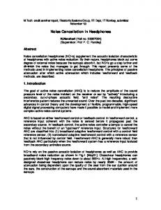
In this study, a practical model of a non-linear Ka-band solid state power amplifier (SSPA) of a user terminal in a satellite return link is considered. The input amplitude/output amplitude (AM/AM) and input amplitude/output phase (AM/PM) characteristics are presented in Fig. 1. The effects of the non-linear distortion on the received 16-QAM symbols are presented in Figs. 2 and 3 for TDMA, SC-FDMA and OFDMA
III. I TERATIVE CANCELLATION OF NON - LINEAR DISTORTION
In this section, the non-linear distortion in the channel is elaborated, a suitable iterative receiver is presented that performs iterative IMI cancellation for the sake of the maximization of the received SNR, followed by analytical modeling of the performance.
Copyright (c) 2015 IEEE. Personal use is permitted. For any other purposes, permission must be obtained from the IEEE by emailing
[email protected].
This is the author's version of an article that has been published in this journal. Changes were made to this version by the publisher prior to publication. The final version of record is available athttp://dx.doi.org/10.1109/TCOMM.2015.2424241 4
IEEE TRANSACTIONS ON COMMUNICATIONS
Fig. 1: AM/AM and AM/PM transfer characteristics of an SSPA.
according to (2). In TDMA, roll-off factors of 5% and 20% are assumed. In addition, a block of 2048 symbols is assigned to 32 users with 64 localized symbols per user. A similar setup of the subcarrier frame, number of users and subcarriers per user is considered in SC-FDMA and OFDMA. As a result, a large degree of symbol multiplexing is achieved in the latter two schemes, in order to obtain a stable signal distribution. In Figs. 2 and 3, the amplitude of the attenuation factors and the variance of the non-linear distortion noise are presented as a function of the OBO. TDMA and SC-FDMA experience an almost identical warping of the amplitude of the received centroids. The three distinct symbol amplitudes in the 16-QAM constellation have three distinct attenuation factors and noise variances. The degree of attenuation and the noise variance correspond to the PAPR of the schemes. TDMA with 20% roll-off experiences the least distortion, followed by TDMA with 5% roll-off, SC-FDMA and OFDMA. It can be noticed that received symbols in OFDMA are expectedly scaled by a single attenuation factor and have the largest noise variance. It should be noted that the truncation of the SRRCF impulse response (16 periods considered with an oversampling factor of 8) to reduce the processing complexity and latency in TDMA contributes additional non-linear distortion noise which is evident in the high OBO region, and it is more prominent in TDMA with 5% roll-off. B. Iterative receiver for cancellation of non-linear distortion noise The receiver can extract the useful signal information in the IMI by means of interference cancellation. It has been first proposed in [7] for systems with OFDMA. A set of received symbols, e.g. a received frame, is buffered. In the first iteration, the symbols are demodulated. Based on the knowledge of the distortion function along the transmission chain, the demodulated symbols are used to obtain an estimate of the received symbols, which is subtracted from the scaled demodulated symbols to obtain an estimate of the interfering component. It is then subtracted from the buffered symbols to obtain a new set of received symbols as an output of the first iteration of IMI cancellation. In the original approach, one factor is used to scale all the constellation symbols. In the second iteration, the newly obtained received symbols are demodulated and used
Fig. 2: Attenuation factor of the non-linear distortion for 16-QAM with an SSPA in return link.
Fig. 3: Variance of non-linear distortion noise for 16-QAM with an SSPA in return link.
to better estimate the interfering component which is again subtracted from the originally buffered received symbols. The output of this process are the newly obtained received symbols after a number of iterations. Finally, the buffer is released and a new set of received symbols is processed. The IMI cancellation approach has been studied for coded OFDMA signals in [8] and adopted for systems with SC-FDMA in [9, 10]. However, the same estimator for the interfering component based on a single scaling factor for all symbols from (2) is applied. This approach is suboptimum for SC-FDMA and TDMA, where individual scaling factors for each constellation point need to be computed as shown in Fig. 2. The block diagram of the proposed modified receiver is presented in Fig. 4. This block diagram can be considered as representative for all types of commercial digital communication systems. In addition, it describes the forward as well as
Copyright (c) 2015 IEEE. Personal use is permitted. For any other purposes, permission must be obtained from the IEEE by emailing
[email protected].
This is the author's version of an article that has been published in this journal. Changes were made to this version by the publisher prior to publication. The final version of record is available athttp://dx.doi.org/10.1109/TCOMM.2015.2424241 SUBMITTED PAPER
5
Fig. 4: Block diagram of a digital transmission scheme with an iterative receiver, performing cancellation of the non-linear distortion noise.
the return links, where the major differences are related to the data framing and signal multiplexing, as well as the resulting channel and distortion functions. Due to the added processing complexity, the receiver is more suitable for application in the return link, where the complexity is confined at the server side. However, when user equipment for professional applications is considered, a higher computational load can be afforded at the user side, and the system can benefit from the application of the proposed receiver in the forward link. After the symbol demultiplexing stage, the received symbols are buffered for further processing. At this point, estimates of the received constellation centroids and the respective scaling factors, Kcm , are calculated for every constellation point, cm , m = 1, ..., M , where M is the modulation order. This can be performed in several ways. First, training frames can be used at the beginning of the transmission, involving a number of symbols for every constellation point. This method can be used in a time invariant channel. In slow fading or mobile channels, pilot symbols in the frame can be employed, e.g. in the preamble, given the pilot overhead is tolerable. In the case when the transmitter is the main contributor to the non-linear distortion and if the channel state information is available, the transmitter can estimate the dislocation of the constellation centroids in an offline setup and signal it to the receiver. Finally, if the dynamics in the system prohibit the application of the above methods, the received centroids can be estimated directly from the received data using mode estimation techniques [16, 17] for the M modes of the received probability distribution function. The scaling factors, Kcm , can be obtained as the ratio of received centroid and transmitted constellation point. The received centroids and the associated scaling factors are stored in a look-up table for every user, so they can be used in the subsequent processing blocks. In satellite communications, where TDM(A) is used, the demodulation is performed over long symbols frames, e.g. 1616 symbols per burst (of which 140 symbols are in header) in DVB-RCS2 return link and 16984 symbols per physical layer frame (of which 784 symbols are pilots and header) in DVB-S2X forward link. In
such a setup, stable statistics of the constellation warping can be obtained, which implies stable scaling factors over time. In addition, a single modulation format is employed on the frame to be demodulated, and the channel is static. Therefore, the scaling factors can be estimated in an offline setup and stored in look-up tables for the different modulation orders. The received constellation centroids are used as a reference for the ML demodulator or in the calculation of the log-likelihood ratios (LLRs) in the case of a subsequently applied decoder. The detected symbols (obtained by encoding and modulation of the decoded bits in the case of coded transmission) are used to obtain an estimate of the interfering component and cancel it from the signal in an iterative fashion. The vector of detected symbols used in the i-th iteration can be expressed as follows: b(i−1) = Det [Demux [Eq [ADC [y]]]] , x
(3)
where the ADC block accounts for the receive filter, the ADC and the SRRCF. The order of the equalizer and the demultiplexer may vary in the different systems. For example, time domain equalization in TDMA is performed before demultiplexing of the symbols, frequency domain equalization in SC-FDMA comes between the FFT and the IFFT operations, while the equalizer in OFDMA is applied after the FFT block. Using the model from (2), an estimate of the non-linear distortion noise can be obtained by subtracting the suitably scaled detected symbols from an estimate of the received symbols: [ [ [ ( [ [ (i−1) ]])]]] b d(i) = Demux Eq ADC h ∗ F DAC Mux x −¯ x(i−1) . (4) ¯ (i−1) is scaled Here, every detected symbol in the vector x (i−1) by the respective scaling factor, Kcm , as follows: x ¯m = (i−1) Kcm x bm . This is essential to account for the constellation warping effects in systems, where the non-linear distortion noise is correlated with the signal, such as TDMA and SCFDMA. From the detected symbols, an estimate of the received
Copyright (c) 2015 IEEE. Personal use is permitted. For any other purposes, permission must be obtained from the IEEE by emailing
[email protected].
This is the author's version of an article that has been published in this journal. Changes were made to this version by the publisher prior to publication. The final version of record is available athttp://dx.doi.org/10.1109/TCOMM.2015.2424241 6
IEEE TRANSACTIONS ON COMMUNICATIONS
symbols can be obtained using the knowledge of the distortion sources and the processing blocks along the chain. First, the detected symbols are passed through the known multiplexing block according to the employed transmission scheme. Next, the known SRRCF and the transmitter filter function are applied, followed by the function of the non-linear device. The signal is then passed through the known channel function obtained by means of channel estimation at the receiver, e.g. by means of dedicated pilots in the frame. In the receiver chain, the known receiver filter function and the SRRCF are applied, followed by the known equalizer function to counter the linear distortion in the system and the symbol demultiplexing stage. Knowledge of the linear and non-linear distortion mechanisms is a common assumption in state-of-the-art communication system. The measured frequency response of the filters along the chain and the estimated channel taps are used in the design of the equalizers, e.g. the linear equalizer in DVB-S2X, or the pre-coding techniques, e.g. bit-and-power loading techniques in OFDMA for 4G LTE. The transfer characteristics of SSPAs can be considered relatively stable over time and are commonly used in the linearization electronics that implement signal pre-distortion techniques [6, 18]. The estimate of the interfering component is subtracted from the buffered received symbols, and the demodulation and possibly decoding stages are repeated. The improved received vector of symbols after the i-th iteration can be expressed as follows: x(i) = Demux [Eq [ADC [y]]] − d(i) .
(5)
The iterations continue until no further change is observed at the output of the demodulator and decoder. It is shown in Section IV that even one or two iterations can yield a significant gain. C. Analytical modeling The performance of the IMI cancelling receiver is analyzed in the non-linear channel with AWGN. In OFDMA, the signal follows a close-to-Gaussian distribution for a large number of subcarriers which does not depend on the underlying digital modulation format and modulation order. In addition, the nonlinear distortion noise component is uncorrelated from the signal. These two facts allow for the derivation of a semianalytical model. In this paper, the effective electrical SNR at the detector and the TD metrics are derived for a standard receiver without IMI cancellation and for 1 iteration of IMI cancellation. As shown in Section IV, 1 iteration is sufficient to achieve the majority of power efficiency improvement. In SCFDMA and TDMA, due to the modulation dependent signal distribution [19, 20] and the fact that the non-linear distortion noise component is correlated with the signal resulting in individual scaling factors for the received constellation centroids illustrated in Fig. 2, the analysis is performed only in a Monte Carlo simulation in Section IV. 1) OFDMA without IMI cancellation: In OFDMA, the single attenuation factor for the received subcarriers, K, can be equalized at the single-tap equalizer, and the ML detection is performed with respect to the original constellation. Therefore,
the analysis of the algorithm from (3), (4) and (5) can be performed for a subcarrier. The received frequency-domain subcarrier without IMI cancellation can be expressed from (1) and (2) as follows: W D + . (6) K HK Here, X is the information-carrying subcarrier symbol, D is the non-linear distortion noise, W is the AWGN, and H is the channel gain which is equalized in a ZF fashion. All the symbols are expressed in the frequency domain. According to the Bussgang theorem [11], the time-domain non-linear distortion noise, d, is uncorrelated from the close-to-Gaussian signal, x. In addition, the distortion noise, d, has been proven to be a zero-mean non-Gaussian process in [21]. However, due to the subsequently applied FFT operation, which is essentially a weighted summation of a large number of independent samples, the frequency domain non-linear distortion noise, D, follows a Gaussian distribution according to the central limit theorem [22]. As a result, the effective received electrical SNR, Γ, on a subcarrier can be expressed as follows: X (0) = X +
|K|2 Ps 2 + σAWGN /|H|2 ( 2 )−1 γ −1 B σD + = |K|2 , σx2 |H|2 Rs
Γ = G(γ) =
2 σD
(7)
2 is where Ps = σx2 is the average electrical symbol power, σD 2 the variance of the non-linear distortion noise, σAWGN is the variance of the AWGN, B/Rs is the ratio between the utilized bandwidth and the symbol rate, and G(·) is the function that transforms the SNR in the linear channel, γ, into the received SNR, Γ. The symbol power is expressed as Ps = Es Rs , where Es is the electrical symbol energy. The AWGN variance is 2 given as σAWGN = BN0 , where N0 /2 is the double-sided noise power spectral density. The required SNR for a target BER in the linear channel is defined as γ = Es /N0 .
The attenuation factor of the non-linear distortion can be expressed for the general amplifier transfer function as defined in [11] and derived in [23] as follows: ∗
∗
Cov [x, F (x)] E [xF (x)∗ ] = Var[x] σx2 (∫ +∞ ( 2) )∗ ( ) 2 u = 4 u2 exp − 2 A(u) exp − jϕ(u) du , σx σx 0 (8) where Cov[·] is the covariance operator, Var[·] is the variance operator, (·)∗ is the complex-conjugate operator, E[·] is the √ expectation operator, and j = −1 is the imaginary unit. The signal variance is denoted by σx2 . The amplitude (AM/AM) and phase (AM/PM) components of the non-linear distortion function are given as A(·) and ϕ(·), respectively, and they only depend on the signal amplitude. As (a result, F (x) can be ) expressed as in [23]: F (x) = A(|x|) exp jϕ(|x|) + j arg(x) . The expression after the second equality sign can be obtained in a straightforward fashion taking into account the fact that x is a zero-mean complex-valued process, and so is F (x), since F (·) is generally a symmetric function. The expression K=
Copyright (c) 2015 IEEE. Personal use is permitted. For any other purposes, permission must be obtained from the IEEE by emailing
[email protected].
This is the author's version of an article that has been published in this journal. Changes were made to this version by the publisher prior to publication. The final version of record is available athttp://dx.doi.org/10.1109/TCOMM.2015.2424241 SUBMITTED PAPER
7
after the third equality sign is then derived by evaluating the expectation taking into account the Rayleigh distribution of the signal amplitude.
transfer function as follows: P out OBO = max P out avg
The variance of the non-linear distortion noise is given for the general amplifier transfer function as follows: 2 σD = Var [F (x) − Kx] [ ] = E |F (x)|2 − |K|2 σx2 ( 2) ∫ +∞ 2 u = 2 u exp − 2 A(u)2 du − |K|2 σx2 . σx 0 σx
(9)
Similarly, the expression after the second equality sign can be straightforwardly derived using the definition of K from (8) and the fact that x and F (x) are zero-mean complex-valued processes. The expression after the third equality sign is obtained by substituting the amplitude component of the nonlinear transfer function and evaluating the expectation using the Rayleigh distribution of the signal amplitude.
( 2) )−1 u 2 =P u exp − 2 |A(u)| du . σx 0 (15) In the case of the soft limiter amplifier, the OBO is derived as follows: ( ( ( )))−1 P out 2 max OBOclip = P out Gσx 1 − exp − 2 . (16) max σx out max
(
2 σx2
∫
+∞
2) OFDMA with 1 iteration of IMI cancellation: The received frequency-domain subcarrier after the i-th iteration of IMI cancellation can be expressed as follows [7]: X (i) = X +
2 σD
D W D(i) + − , K HK K
(17)
can be Useful closed-form expressions for K and derived for a soft limiter amplifier, which is also known as an ideal clipper. The transfer function is given as follows: { √ x G, if x ≤ P in , max Fclip (x) = (10) P out , if x > P in ,
where D(i) , with D(0) = 0, is the estimate of the non-linear distortion noise which is computed and subtracted in the i-th iteration. Given the knowledge of the linear and non-linear distortions along the transmission chain, including the channel state information and the non-linear distortion function, the max max estimate D(i) can be obtained as follows: [ [ ( [ ])]] where G is the gain, and P in and P out are the maximum b (i−1) b (i−1) . max max D(i) = Eq FFT h ∗ F IFFT X − KX input and output powers of the HPA. In this case, Kclip and (18) 2 σD,clip can be derived for the soft limiter, respectively, as b (i−1) is the Here, Eq[·] is the equalizer operation, and X follows: ( ) √ ( ) estimate of the received symbols after detection, e.g. after πP out out P out P demodulation, decoding, encoding and modulation, from the max max , previous iteration. Using a ZF equalizer, i.e. Eq[·] = 1/H, the Kclip = G 1 − exp − max + erfc 2 2 σx 2σx σx estimate of the non-linear distortion noise in the first iteration ( ( ( )) ) (11) can be expressed as follows: P out [ ( [ ])] 2 σD,clip = σx2 G 1 − exp − max − |Kclip |2 . (12) b (0) b (0) . D(1) = FFT F IFFT X − KX (19) σx2
In order to quantify the power efficiency penalty induced by the IMI, the TD metric is defined as follows: TD[dB] = OBO + SNR
required in non−lin.chan.
− SNR required in . (13) lin.chan.
In addition to the OBO penalty, the TD incorporates the penalty on the SNR requirement to achieve a target BER in the non-linear channel with respect to the SNR requirement in the linear channel with AWGN. Using the effective received SNR expression from (7), the SNR requirement to achieve a target BER in the non-linear channel can be expressed by means of the inverse function G −1 (·) as G −1 (γ). Therefore, the TD can be derived in the linear domain as a function of the required SNR for a target BER in the linear channel, γ, as follows: ( )−1 2 B OBO σD G −1 (γ) 2 = |K| − γ . (14) TD = OBO γ Rs |H|2 σx2 Here, the OBO can be expressed for a general amplifier
The detector operation is a memoryless operation in the frequency domain, and since the X (0) follows a Gaussian distribution for every symbol X, the Bussgang theorem can be applied to express the detected symbol after the first iteration as follows: ( ) (1) b (0) = a(1) X + b(1) D + W X + Ddet . (20) K HK Here, the attenuation factors for the signal and noise components in the first iteration are denoted as a(1) and b(1) , respectively. The distortion noise at the detector is denoted as (1) Ddet , it is uncorrelated from the signal and noise components, and it has a variance of σ 2 (1) . These parameters are dependent Ddet on the modulation scheme and the modulation order, e.g. M -QAM or M -APSK. In general, they can be expressed in a semi-analytical fashion as follows: ] [ ]∗ [ b (0) b (0) E X ∗X Cov X, X = , (21) a(1) = Var[X] Var[X]
Copyright (c) 2015 IEEE. Personal use is permitted. For any other purposes, permission must be obtained from the IEEE by emailing
[email protected].
This is the author's version of an article that has been published in this journal. Changes were made to this version by the publisher prior to publication. The final version of record is available athttp://dx.doi.org/10.1109/TCOMM.2015.2424241 8
IEEE TRANSACTIONS ON COMMUNICATIONS
b(1) =
[ ]∗ b (0) Cov X (0) − X, X
E
[(
X (0) − X
)∗
b (0) X
]
= , Var[X] Var[X] (22) [ ( )] 2 (0) (1) (1) (0) b σD(1) = Var X − a X − b X −X . (23) det [ ] b (0) is a close-to-Gaussian signal due to the apSince IFFT X plied IFFT, the(non-linear can be [ transformation ]) [ decomposed ] (0) (1) b e b (0) + de(1) , as follows: F IFFT X = K IF F T X e (1) is the respective attenuation factor in the first iterwhere K ation. Here, de(1) is the respective non-linear noise component, e (1) . and its frequency domain representation is denoted as D While uncorrelated from the signal and AWGN components e (1) is correlated with the non-linear distortion noise in (20), D D. The degree of correlation depends on how well the detector can demodulate and decode the message X, i.e. if X (0) = X, e (1) = D. However, since the detector operates in then D the presence of AWGN and the non-linear distortion noise, errors in the detection can be expected depending on the SNR and the OBO as modeled in (20), where X (0) is expressed as a function of X. This correlation can be modeled as follows [13]: e (1) (1) e (1) = K a(1) D + Dres D , K
(24)
(1)
where Dres is the residual noise which is uncorrelated from the signal and noise components. Thus, the estimate of the non-linear distortion noise in the first iteration can be derived as follows: ( ) ( ) e (1) K W (1) (1) (1) e D = K −K a X + − 1 b(1) K H (( ) ) e (1) e (1) K K (25) + − 1 b(1) + a(1) D K K ( ) (1) e (1) − K D(1) + Dres + K . det Inserting (25) into (17), the improved received symbol after the first iteration of IMI cancellation, X (1) , is obtained. Therefore, the improved effective received electrical SNR after the first iteration, Γ(1) , can be expressed as follows: −1 σ 2 (1) −1 βγ B D , Γ(1) = α|K|2 2tot + (26) σx |H|2 Rs ( α = 1 + 1 − ( β = 1 + 1 −
where
2 σD (1) tot
2 a , 2 ) e (1) K (1) b , K
e (1) K K
)
(1)
2 ( ) e (1) e (1) K K 2 = 1 − a(1) + 1 − b(1) σD K K 2 e (1) σ 2 (1) + σ 2 (1) . + K − K D D det
res
(27)
(28)
(29)
Fig. 5: Validation of the analytical model by means of BER performance evaluation, simulation (solid lines) vs. theory (dashed lines).
The variance of the residual noise component can be expressed from (24) as follows: 2 K (1) e 2 (1) 2 2 σD(1) = σDe (1) − a σD . (30) res K e (1) , and the Here, the attenuation factor in the first iteration, K variance of the non-linear distortion noise in the first iteration, 2 σD e (1) , can be obtained from (8) and (9) (or (11) and (12) in the case of the soft limiter amplifier), when)σx2 is re( 2 respectively, (1) 2 2 (1) 2 2 placed by |a | σx + |b | σD + Bσx /(γRs |H|2 ) /|K|2 + σ 2 (1) , as the latter expression is the variance of the input Ddet [ ] b (0) , to the non-linear distortion function signal, IFFT X F (·). The derived SNR after the first iteration, can be used to derive the TD as follows: −1 2 σ (1) B OBO D TD(1) = . (31) β α|K|2 − γ 2tot Rs |H|2 σx 3) Validation: The analytical model is verified against a Monte Carlo BER simulation. For this purpose, the amplifier characteristics from Fig. 1 are assumed, and 2048 OFDMA subcarriers are shared among 32 users in a return link setup with 64 subcarriers per user. The subcarriers are modulated by means of M -QAM symbols. The derived expressions for the effective received electrical SNR are inserted in the analytical model for the BER in M -QAM [24]: (√ ) √ 3 log2 (M ) 4( M − 1) √ Q Γ . (32) BER = M −1 log2 (M ) M The results for QPSK and 16-QAM with 4 and 8 dB OBO settings, i.e. scenarios with high and low IMI, are presented in Fig. 5. The numerical and analytical approaches exhibit a close
Copyright (c) 2015 IEEE. Personal use is permitted. For any other purposes, permission must be obtained from the IEEE by emailing
[email protected].
This is the author's version of an article that has been published in this journal. Changes were made to this version by the publisher prior to publication. The final version of record is available athttp://dx.doi.org/10.1109/TCOMM.2015.2424241 SUBMITTED PAPER
match. The results show that 1 iteration of IMI cancellation significantly improves the BER in the low-OBO scenario, and it provides a notable gain in the power efficiency. IV. P ERFORMANCE COMPARISON The performance of the proposed receiver is evaluated in a Monte Carlo simulation in a return link setup for three different transmission schemes, i.e. TDMA, SC-FDMA and OFDMA. A similar setup as the one described in Section III is used. A processing block of 2048 symbols is assigned to 32 users. Here, 64 symbols are assigned to a user in a localized fashion. In TDMA, the tested 5% and 20% roll-off factors increase the bandwidth occupation of a carrier accordingly. An oversampling factor of 8 is considered. It is shown in [25] that two contiguous aggregated carriers based on OFDMA or SCFDMA can be employed with as little as 5% guard band. The channel in the satellite link can be considered as flat-fading over the user bandwidth, and the channel gain can be equalized at the receiver gateway. Since no further linear distortion is introduced in the return link channel, i.e. there is no multipath fading, a unity channel is assumed, in order to focus the testing and comparison on the management of the IMI. The non-linear SSPA of a satellite user terminal is considered as the non-linear distortion source at the transmitter, when very low OBO is used. In the considered setup, 256 symbols (e.g. 16 symbols per constellation point in 16-QAM) are used for estimation of the received centroids in an offline setup given the knowledge of the amplifier transfer characteristic and the signal processing blocks along the chain. In TDMA, even though the SRRCF at the transmitter is matched to the one at the receiver, there is a residual non-linear distortion for low roll-off-factors, due to the truncation of the filter impulse response to reduce the processing complexity and latency. The improved IMI cancellation receiver is tested against the stateof-the-art IMI cancellation receiver which is studied in [7–10] for OFDMA and SC-FDMA, referred to as standard receiver, where a single attenuation factor for the received symbols is used in the IMI cancellation procedure. In addition, the standard receiver is also tested in the case, where data predistortion is employed at the transmitter. The receivers are tested in three iteration scenarios of IMI cancellation: no iterations/no IMI cancellation, 1 iteration and 2 iterations. In this study, the SNR requirement and spectral efficiency of SC-FDMA is compared with OFDMA and state-of-the-art TDMA. The results for the TD in QPSK and 16-QAM are presented in Figs. 6 and 7. The standard receiver is labeled as ”std. Rx”, the standard receiver with pre-distortion at the transmitter is labeled as ”pre-dist.”, and the improved receiver is labeled as ”impr. Rx”. SNR values of 3.7 dB and 10.5 dB are chosen for QPSK and 16-QAM, respectively. These SNR values correspond to the SNR requirement of the modulation schemes to achieve a BER target of 10−3 , sufficient to enable FEC, in the linear channel with AWGN, where the gain of 6.1 dB in the linear region of the SSPA from Fig. 1 is considered. Without IMI cancellation, the improved receiver shows a lower TD for higher order modulation as compared to the standard receiver, e.g. up to 0.2 dB for 16-QAM with TDMA
9
with 20% roll-off. While the standard receiver performs AGC on the received warped constellation with respect to the original transmit constellation and uses the latter as a reference for the ML detection, the improved receiver estimates the warped received constellation centroids and applies the estimate as a reference for the ML detection to achieve the gain. TDMA with 20% roll-off shows the lowest TD in the non-linear channel followed by SC-FDMA and OFDMA. In addition, SC-FDMA is able to outperform TDMA with 5% roll-off for higher constellation orders due to the residual non-linear distortion noise for very low roll-off factors, resulting from the truncation of the SRRCF impulse response. When iterative IMI cancellation is employed, the improved receiver consistently outperforms the standard receiver for all OBO values. This is due to two significant improvements related to signals which exhibit correlation with the non-linear distortion noise and experience constellation warping effects, such as TDMA and SC-FDMA. On one hand, the improved receiver employs the estimate of the received constellation centroids as a reference of the ML detection. On the other hand, an individual scaling factor is used for each received symbol in the procedure for estimation of the non-linear distortion noise and its cancellation. The results demonstrate that the iterative receivers shift the minimum TD values to lower OBO values, improving the power efficiency. Data predistortion at the transmitter applied with the standard receiver is shown to be an effective technique to reduce the nonlinear distortion for higher order modulation. However, the proposed receiver with estimation of the received centroids also consistently outperforms the standard receiver with data pre-distortion. This is due to the fact that data pre-distortion increases the PAPR of the waveform which increases the distortion noise [4, 6, 12]. Due to the minimal constellation warping in QPSK, the receivers show similar performance for given number of iterations and transmission scheme. Two iterations of IMI cancellation show the following gains for QPSK: 0.1 dB for TDMA with 20% roll-off, 0.2 dB for TDMA with 5% rolloff, 0.3 dB for SC-FDMA and 1.1 dB for OFDMA. This is in accord with the PAPR and the degree of multiplexing of the symbols in the different transmission schemes. The minimum TD and OBO of the standard and improved receivers are summarized in TABLE I for 16-QAM with 0, 1 and 2 iterations. It is shown that iterative IMI cancellation enables the application of lower OBO. The optimum OBO for 16-QAM is reduced from 3.6 dB to 2.95 dB in TDMA with 20% roll-off, from 4.35 dB to 3 dB in TDMA with 5% roll-off, from 5.17 dB to 3.63 dB in SC-FDMA and from 6.25 dB to 3.39 dB in OFDMA. The improved receiver with two iterations of IMI cancellation shows the following gains for 16-QAM relative to the standard receiver without IMI cancellation: 0.8 dB for TDMA with 20% roll-off, 1.9 dB for TDMA with 5% roll-off, 1.1 dB for SC-FDMA and 2.5 dB for OFDMA. Adding the TD values to the corresponding SNRs, the spectral efficiency is presented as a function of the SNR requirement in Fig. 8 for the improved receiver. Here, also 8-PSK with a SNR of 8.9 dB is included in addition to QPSK and 16-QAM to represent the modulation formats of the DVB-
Copyright (c) 2015 IEEE. Personal use is permitted. For any other purposes, permission must be obtained from the IEEE by emailing
[email protected].
This is the author's version of an article that has been published in this journal. Changes were made to this version by the publisher prior to publication. The final version of record is available athttp://dx.doi.org/10.1109/TCOMM.2015.2424241 10
IEEE TRANSACTIONS ON COMMUNICATIONS
Number of iterations Receiver TDMA, 20% roll-off TDMA, 5% roll-off SC-FDMA, 5% guard OFDMA, 5% guard
No iterations std. Rx impr. Rx
[email protected] [email protected] [email protected] [email protected] [email protected] [email protected] [email protected] [email protected]
One iteration std. Rx impr. Rx
[email protected] [email protected] [email protected] [email protected] [email protected] [email protected] 5.54@4 5.54@4
Two iterations std. Rx impr. Rx
[email protected] [email protected] [email protected] 4.67@3
[email protected] [email protected] [email protected] [email protected]
TABLE I: Minimum TD [dB] @ optimum OBO [dB] of digital transmission schemes for 16-QAM with an SSPA and AWGN in return link.
(a) No iterations.
(a) No iterations.
(b) One iteration.
(b) One iteration.
(c) Two iterations. Fig. 6: TD vs. OBO of digital transmission schemes for QPSK with an SSPA and AWGN in return link.
(c) Two iterations. Fig. 7: TD vs. OBO of digital transmission schemes for 16-QAM with an SSPA and AWGN in return link.
Copyright (c) 2015 IEEE. Personal use is permitted. For any other purposes, permission must be obtained from the IEEE by emailing
[email protected].
This is the author's version of an article that has been published in this journal. Changes were made to this version by the publisher prior to publication. The final version of record is available athttp://dx.doi.org/10.1109/TCOMM.2015.2424241 SUBMITTED PAPER
11
V. C ONCLUSION
Fig. 8: Spectral efficiency vs. electrical SNR requirement of digital transmission schemes with an SSPA and AWGN in return link.
RCS2 satellite return link standard [3]. SC-FDMA and TDMA with 5% roll-off are shown to be the most spectrally efficient transmission scheme in the tested scenarios with the improved IMI cancelling receiver, while it allows OFDMA to close the gap for higher order modulation. The gains in the power efficiency of the improved receiver with IMI cancellation relative to the standard receiver without IMI cancellation are summarized hereafter. OFDMA is able to demonstrate a higher power efficiency gain of 1.1 − 2.5 dB for the three modulation formats (QPSK, 8-PSK, 16-QAM) with 2 iterations relative to no iterations/no IMI cancellation. In SC-FDMA, the gain is in the range of 0.3 − 1.1 dB. In TDMA with 20% roll-off, gains in the range of 0.1 − 0.8 dB are observed, while gains in the range of 0.2 − 1.9 dB are presented in TDMA with 5% roll-off. It is generally observed that 1 iteration of both the standard and the improved receivers is sufficient to obtain the major portion of the gain of the iterative IMI cancellation, while 2 iterations only contribute with an inconsiderable further improvement. Only OFDMA is able to show further gain for 2 iterations with the improved receiver. Also, the improved receiver is able to obtain more stable statistical estimates of the received constellation centroids from the received symbols, even if lower number of realizations is used, such as 64 symbols per user in the tested scenario. The standard and improved receivers expectedly have a similar performance for QPSK and 8-PSK due to the small envelope variations of the waveform. Also, OFDM does not distinguish between the two receivers due to the uncorrelated non-linear noise component, yet they both show significant gains for higher order modulation. However, when applied with signals which experience constellation warping in the non-linear channel, such as TDMA and SC-FDMA with higher order modulation, the improved receiver with IMI cancellation shows significant gains in power efficiency as compared to the standard receiver, especially when the operating OBO deviates from the optimum point.
In this paper, an iterative receiver has been presented which performs cancellation of the IMI that originates from the nonlinear distortion in the channel. The performance of singlecarrier transmission schemes such as TDMA and SC-FDMA is maximized by the joint application of ML detection with respect to the received constellation centroids and non-linear noise cancellation using individual scaling factors for the detected symbols. The proposed receiver can be applied in all types of commercial digital communication systems. These include terrestrial mobile wireless communications, DSL and cable communications, satellite communications and optical wireless communications such as infrared communications and VLC. In addition, it can be applied in both the forward and the return links. The receiver has been tested with TDMA, SCFDMA and OFDMA transmission formats, and it has demonstrated significant gains in the power efficiency. An analytical model has been developed for 1 iteration of IMI cancellation in OFDMA. It has been shown that even 1 iteration is sufficient to present the majority of the gain of IMI cancellation in the tested transmission schemes. In the considered modulation setup, gains of up to 2.5 dB are expected for OFDMA, 1.1 dB for SC-FDMA, 0.8 dB for TDMA with 20% roll-off and 1.9 dB for TDMA with 5% roll-off. The receiver is particularly suitable for application with higher order modulation formats which are more vulnerable to non-linear distortion, and as a result higher gains are expected. Consequently, higher spectral efficiency can be achieved which can be translated into higher throughput and lower cost per transmitted bit. R EFERENCES [1] Broadband Access via Integrated Terrestrial and Satellite Systems (BATS), “ICT-2011.1.1 BATS D4.1: Satellite Network Mission Requirements,” European Project, Tech. Rep., 2012. [2] Second generation framing structure, channel coding and modulation systems for Broadcasting, Interactive Services, News Gathering and other broadband satellite applications; Part II: S2-Extensions (DVBS2X) - (Optional), Digital Video Broadcasting (DVB) Std. ETSI EN 302 307-2, Mar. 2014. [3] Second Generation DVB Interactive Satellite System (DVB-RCS2); Part 2: Lower Layers for Satellite Standard, Digital Video Broadcasting (DVB) Std. ETSI EN 301 545-2, Jan. 2012. [4] E. Casini, R. De Gaudenzi, and A. Ginesi, “DVB-S2 Modem Algorithms Design and Performance Over Typical Satellite Channels,” International Journal of Satellite Communications and Networking, vol. 22, pp. 281– 318, Jun. 2004. [5] V. Dalakas, P. Mathiopoulos, F. Do Cecca, and G. Gallinaro, “A Comparative Study Between SC-FDMA and OFDMA Schemes for Satellite Uplinks,” IEEE Transactions on Broadcasting, vol. 58, no. 3, pp. 370–378, Sep. 2012. [6] G. Karam and H. Sari, “Analysis of Predistortion, Equalization, and ISI Cancellation Techniques in Digital Radio Systems with Nonlinear Transmit Amplifiers,” IEEE Transactions on Communications, vol. 37, no. 12, pp. 1245–1253, Dec. 1989. [7] H. Chen and A. M. Haimovich, “Iterative Estimation and Cancellation of Clipping Noise for OFDM Signals,” IEEE Communications Letters, vol. 7, no. 7, pp. 305–307, Jul. 2003. [8] R. Djardin, M. Colas, and G. Gelle, “Comparison of Iterative Receivers Mitigating the Clipping Noise of OFDM Based System,” in Proc. of European Wireless Conference 2007, Paris, France, Apr. 2007. [9] J. Gazda, P. Drotar, M. Deumal, D. Kocur, and P. Galajda, “Simple Iterative Cancellation of Nonlinear Distortion in LDFMA Systems,” in Proc. of 14th International OFDM Workshop 2009, Hamburg, Germany, Apr. 2009, pp. 133–137.
Copyright (c) 2015 IEEE. Personal use is permitted. For any other purposes, permission must be obtained from the IEEE by emailing
[email protected].
This is the author's version of an article that has been published in this journal. Changes were made to this version by the publisher prior to publication. The final version of record is available athttp://dx.doi.org/10.1109/TCOMM.2015.2424241 12
IEEE TRANSACTIONS ON COMMUNICATIONS
[10] J. Gazda, “Iterative Receiver for Nonlinearly Distorted SC-FDMA Tranmission,” in Proc. of 10th Scientific Conference of Young Researchers (SCYR 2010), Kosice, Slovak Republic, 2010, pp. 133–137. [11] J. Bussgang, “Cross Correlation Function of Amplitude-Distorted Gaussian Signals,” Research Laboratory for Electronics, Massachusetts Institute of Technology, Cambridge, MA, Technical Report 216, Mar. 1952. [12] G. Karam and H. Sari, “A Data Pre-distortion Technique with Memory for QAM Radio Systems,” IEEE Transactions on Communications, vol. 39, no. 2, pp. 336–344, Aug. 1991. [13] E. Vanin, “Analyical Model for Optical Wireless OFDM Systems with Digital Signal Restoration,” in Proc. of IEEE GLOBECOM Workshops 2012 (GC Wkshps 2012), Anaheim, CA, USA, 3-7 2012, pp. 1213–1218. [14] H. G. Myung, J. Lim, and D. J. Goodman, “Single Carrier FDMA for Uplink Wireless Transmission,” IEEE Vehicular Technology Magazine, vol. 1, no. 3, pp. 30–38, Sep. 2006. [15] D. Benfatto, N. Privitera, R. Suffritti, A. Awoseyila, B. Evans, and S. Dimitrov, “On Acquisition and Tracking Methods for SC-FDMA over Satellite,” in in Proc. of 7th Advanced Satellite Multimedia Systems Conference (ASMS2014), Livorno, Italy, Sep. 8-10 2014. [16] S. Dutta and A. Goswami, “Mode Estimation for Discrete Distributions,” Mathematical Methods for Statistics, vol. 19, no. 4, pp. 374–384, 2010. [17] M. A. Carreira-Perpinan, “Mode-Finding for Mixtures of Gaussian Distributions,” IEEE Transactions on Pattern Analysis and Machine Intelligence, vol. 22, no. 11, pp. 1318–1323, 2000. [18] R. Gray, A. Katz, and R. Dorval, “Advances in Ka/Q Band Linearization,” Linearizer Technology Inc., Tech. Rep., 2012. [19] H. Ochiai, “Exact and Approximate Distributions of Instantaneous Power for Pulse-shaped Single-carrier Signals,” IEEE Transactions on Communications, vol. 10, no. 2, pp. 682–692, Feb. 2011. [20] ——, “On Instantaneous Power Distributions of Single-carrier FDMA Signals,” IEEE Wireless Communications Letters, vol. 1, no. 2, pp. 73– 76, Apr. 2012. [21] D. Dardari, V. Tralli, and A. Vaccari, “A Theoretical Characterization of Nonlinear Distortion Effects in OFDM Systems,” IEEE Transactions on Communications, vol. 48, no. 10, pp. 1755–1764, Oct. 2000. [22] J. Rice, Mathematical Statistics and Data Analysis, 2nd ed. Duxbury Press, 1995. [23] P. Banelli and S. Cacopardi, “Theoretical Analysis and Performance of OFDM Signals in Nonlinear AWGN Channels,” IEEE Transactions on Communications, vol. 48, no. 3, pp. 430–441, Mar. 2000. [24] I. A. Glover and P. M. Grant, Digital Communications, 2nd ed. Pearson Prentice Hall, 2004. [25] Technical Specification Group Radio Access Network; Evolved Universal Terrestrial Radio Access (EUTRA); User Equipment (UE) Radio Transmission and Reception, 3rd Generation Partnership Project Std. 3GPP TS 36.101, 2011.
Svilen Dimitrov (S’09-M’13) received the BSc degree in electrical engineering and computer science in 2008, and the MSc degree in communications, systems and electronics in 2009 from Jacobs University Bremen, Germany. He obtained his PhD degree in electrical engineering in 2012 from the University of Edinburgh, UK. He wrote his BSc thesis, MSc thesis and PhD thesis in collaboration with Airbus Germany, EADS Germany, and EADS UK. Work included the modeling of the optical wireless channel in an aircraft cabin through Monte Carlo ray-tracing techniques and maximization of throughput of digital modulation schemes for optical wireless communications with non-linear distortion. From 2013, he is appointed as a project manager at the German Aerospace Center (DLR). His main interests are the research and development of next generation communication systems, including satellite communications, terrestrial mobile communications and optical wireless communications (Li-Fi), computer-aided design, test and optimization, channel modelling, modulation techniques, air interface design, interference and resource management. He has published articles in highly renowned journals, such as IEEE JSAC, IEEE TCOM, IEEE/OSA JLT, and conferences, such as IEEE GLOBECOM, IEEE ICC, IEEE VTC, EuCAP, EuCNC, ASMS and Ka Conference. He is co-author of the book ”Principles of LED Light Communications: Towards Networked Li-Fi” by Cambridge University Press.
Copyright (c) 2015 IEEE. Personal use is permitted. For any other purposes, permission must be obtained from the IEEE by emailing
[email protected].