Structural Monitoring and Maintenance, Vol. 1, No. 1 (2014) 089-110 89
DOI: http://dx.doi.org/10.12989/smm.2014.1.1.089
Iterative damage index method for structural health monitoring 3
Taesun You1, Paolo Gardoni2 and Stefan Hurlebaus 1
Texas A&M Transportation Institute, College Station, TX 77843-3135, USA Department of Civil and Environmental Engineering, University of Illinois at Urbana-Champaign, Urbana, IL61801-2351, USA 3 Zachry Department of Civil Engineering, Texas A&M University, College Station, TX 77843-3136, USA 2
(Received March 3, 2014, Revised March 15, 2014, Accepted March 24, 2013) Abstract. Structural Health Monitoring (SHM) is an effective alternative to conventional inspections
which are time-consuming and subjective. SHM can detect damage early and reduce maintenance cost and thereby help reduce the likelihood of catastrophic structural events to infrastructure such as bridges. After reviewing the Damage Index Method (DIM), an Iterative Damage Index Method (IDIM) is proposed to improve the accuracy of damage detection. These two damage detection techniques are compared based on damage on two structures, a simply supported beam and a pedestrian bridge. Compared to the traditional damage detection algorithm, the proposed IDIM is shown to be less arbitrary and more accurate. Keywords: vibration-based damage identification method; damage index method; damage detection
algorithm; structural health monitoring
1. Introduction Recently, effective inspection and maintenance for infrastructure are placing great importance because infrastructures are deteriorating after construction due to fatigue and corrosion. The Bureau of Transportation Statistics (2008) reported that nearly 26 percent of the bridges in the U.S. are substandard. Traditional inspection procedures for bridges generally rely on subjective and irregular visual examination. As such, there are variations in the inspection results even for the same structure because of the differences in inspectors’ experience and judgment. Visual checking is also apt to be a schedule-based inspection process. Discrete inspection processes can fail to detect hidden effects of poor design or maintenance that can be the source of sudden and dangerous events such as a bridge collapse. Between 1989 and 2000, out of 65 bridge failures (caused by design, detailing, construction, maintenance, or material problems), 43 failures were attributed to poor maintenance (Wardhana and Hadipriono 2003). As an alternative to periodic inspections, structural health monitoring (SHM) is a continuous process (Hurlebaus and Gaul 2006) that can detect damage early, reduce the cost of repair and rehabilitation, and help reduce the chance of catastrophic events with the structures. A number of studies have sought to improve the accuracy of damage detection using SHM. Several researchers (Lenzen 2005, Kim and Kawatani 2007, Kim et al. 2008, Mizuno et al. 2008,
Corresponding author, Associate Professor, E-mail:
[email protected] Copyright © 2014 Techno-Press, Ltd. http://www.techno-press.org/?journal=smm&subpage=7
ISSN: 2288-6605 (Print), 2288-6613 (Online)
90
Taesun You, Paolo Gardoni and Stefan Hurlebaus
Park et al. 2009, Kim et al. 2013) have developed damage identification methods using the analysis of dynamic responses of a structure. However, the damage can be estimated where the dynamic responses are recorded. On the other hand, many studies took advantages of the development of instrumentation using sensors that facilitates observation of the dynamic characteristics of a structure, such as frequencies and modeshapes. For example, Pandey et al. (1991) proposed to track the changes in modeshapes curvature while Pandey and Biswas (1994) used flexibility changes. Zhang and Aktan (1995) combined the two methods proposed by Pandey et al. (1991) and Pandey and Biswas (1994), and developed a method using the changes in flexibility curvature. Shi et al. (2000) introduced the correlation between the measured modeshapes change for the undamaged and damaged and the analytical modeshapes change for the undamaged and damaged. If the correlation between the measured modeshapes and analytical changes is unity, the damage is estimated correctly. Despite those efforts, the methods are not practical in infrastructure such as bridges and buildings. This is often the case because small changes in physical properties do not alter frequencies and modeshapes enough to allow their detection. In other case, it is difficult to obtain as many modes as these methods need from these complicated structures. To overcome the limitations, Stubbs and Kim (1996) suggested a Damage Index Method (DIM) using modal strain energy to detect damage. This paper refers to the measured points on a structure as recording points. Interpolation between selected recording points is then used to make the modeshapes a smooth line. In this paper, the points used in interpolating the modeshapes are called spline points. Note the number of spline points, Ns, is always equal to or greater than the number of recording points, Nr and a cubic spline interpolation function is chosen in this study to avoid Runge’s phenomenon which can be occurred when using polynomial interpolation method. Several researchers (Stubbs and Kim 1996, Stubbs and Park 1996, Kim and Stubbs 2002, Kim et al. 2003) verified the accuracy of the DIM with numerical simulation models, while others confirmed its usefulness with experimental evaluation (Park et al. 2001, Kim and Stubbs 2003, Kim et al. 2007, Choi et al. 2008). Moreover, Huang et al. (2009) applied the DIM to find the probabilistic capacity and fragility of reinforced concrete columns. Compared with commonly used vibration-based damage detection methods, the DIM is the most accurate (Alvandi and Cremona 2006, Humar et al. 2006). The DIM relies on the calculation of the modal strain energy by measuring the modeshapes of a structure to detect damage. However, the current DIM has two limitations with regard to this calculation. First, the selection of a fixed threshold to determine whether there is enough change in the measurable physical properties to indicate damage in a structure is arbitrary. Second, the damage detection with any fixed threshold is affected by the number of spline points selected. The purpose of the work described in this paper is to develop a less arbitrary and more accurate vibration-based damage detection method for SHM. A modified DIM, referred to as the Iterative Damage Index Method (IDIM), is proposed. The proposed IDIM does not require defining an arbitrary threshold to identify damage and it is independent of Ns. Thus, the proposed method .promises a generally better and reliable detection of damage. The remaining of this paper consists of four sections. The technical background is described in the following section. After a brief review of the algorithms used by the current DIM, the proposed IDIM is described. Then, the accuracy of damage prediction using the DIM and the IDIM for a simply supported beam and a pedestrian bridge are compared using numerical and experimental data. Finally, the last section summarizes the findings of this paper and suggests some future work.
Iterative damage index method for structural health monitoring
91
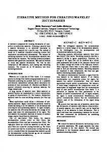
2. Damage detection algorithm First, the quantification of the accuracy of predicted damage by damage identification methods is presented. After that, two damage detection algorithms are explained: DIM and IDIM. 2.1 Damage index method This section reviews the DIM proposed by Stubbs and Kim (1996). Assuming a structural element can be considered as a Euler-Bernoulli beam (see Fig. 1), the modal strain energy associated to the ith mode of undamaged beam, K i , can be calculated as 2
L Ki EI x i x dx 0
(1)
where L is the length of the beam, EI is the flexural rigidity, and i is the curvature of the ith modeshape. Dividing the beam into n segments, the modal strain energy contribution from the jth segment to the ith mode, k ij , is given by 2
b ki j EI j i x dx a
(2)
where the jth segment is between x a and b. As such, the fraction of the jth segment’s contribution to the total modal strain energy, Fi j , can be expressed as
Fi j
ki j
(3)
Ki
L 1st segment
x
5th segment
jth segment
a b
Fig. 1 Structural element with n segmetns
nth segment
92
Taesun You, Paolo Gardoni and Stefan Hurlebaus
Similarly, for the corresponding damaged element, we have 2
L K i d EI d x id x dx 0
(4)
2
b ki j d EI d j x id x dx a
Fi j d
(5)
ki j d
(6)
Ki d
where the superscript ‘d’ denotes ‘damaged’. Assuming that the fraction of the jth element’s contribution to the ith modal strain energy in the undamaged and damaged structure remains constant (i.e., Fi j Fi j d ), the ratio of the jth segment flexural rigidity in the undamaged and damaged structure is given by
j where
j
EI j EI
d j
L
0
2
EI x i x dx 2 b a i x dx
2
d a i x dx 2 L d d x dx EI x 0 i b
is the damage index for the jth segment. For multiple modes, 2 L x dx EI x i 0 j 2 b i 1 x dx a i nm
j
(7)
is expressed as
2 d x dx i a 2 L d d 0 EI x i x dx b
(8)
where nm is the number of modes. Accordingly, the normalized damage index (damage indicator), Z j , is obtained as
Zj
j
(9)
where and are the mean and the standard deviation of the damage index, respectively. For a chosen threshold, Z threshold , if Z j Z threshold , it is indicated that the jth segment is damaged. In this paper, Z threshold is chosen to be one, meaning that the confidence level for damage detection is 84.1% (Park et al. 2001). A flowchart shown in Fig. 2 depicts the entire procedure of the current DIM. As mentioned in the previous section, there are two crucial restrictions in the use of the DIM. First, the choice of a fixed threshold is arbitrary. Because the particular fixed threshold chosen drives the damage detection results, the selection of the threshold is critical in the DIM. If the selected threshold is smaller than the limit at which actual damage occurs, damage size would be overestimated. In contrast, damage size would be underestimated if the selected threshold is set too
93
Iterative damage index method for structural health monitoring
high. As an illustration, in Fig. 3(a) is an appropriate threshold, (b) is a smaller threshold, and (c) is a larger threshold. Although the DIM has this problem with the selection of a fixed threshold to detect damage, various thresholds have been selected. For instance, the threshold was chosen to be one by some researchers (Park et al. 2001, Kim and Stubbs 2003, Kim et al. 2007, Choi et al. 2008, Huang et al. 2009) while other researchers selected thresholds of two (Stubbs and Kim 1996, Stubbs and 2002) and three (Kim and Stubbs 2003, Kim et al. 2007).
j=0
Fig. 2 Flow chart of the Damage Index Method
94
Taesun You, Paolo Gardoni and Stefan Hurlebaus
Fig. 3 Damage detection with (a) appropriate threshold, (b) smaller threshold and (c) larger threshold
4
Detected damage size
Damage Indicator - Z
3
Fixed threshold
2
1
0
-1
Actual damage size
Segment Number
(a)
Damage Indicator - Z
4
Detected damage size 3
Fixed threshold
2 1 0 -1
Actual damage size
Segment Number
(b)
Fig. 4 Damage detection results with (a) Nr recording points and Ns-1 spline points and (b) Nr recording points and Ns-2 spline points (Ns-1


![[04] 02.Integrated.fm - Techno Press](https://m.moam.info/img/260x300/04-02integratedfm-techno-press_5b290191097c47756b8b456a.jpg)