SETIT 2009
5th International Conference: Sciences of Electronic, Technologies of Information and Telecommunications March 22-26, 2009 – TUNISIA
Contribution to the Study of the Planar Circuits by a Hybrid Method (Iterative Method + FDTLM Method) Mohamed GLAOUI, Hassen ZAIRI and Hichem TRABELSI Faculté des sciences de Tunis 2092 El Manar Tunisia
[email protected] [email protected] [email protected] Abstract: The new method of numerous simulations is considered as hybrid. It is based on concept of waves. With this method we can win a lot of times in the course of simulation and opening other perspectives in the circuit of microstrip study. This method is considered as combination between WCIP methods (Wave Concept Iterative Method) and FDTLM methods (Frequency Domain Transmission Line Matrix. Key words: FDTLM, WCIP, hybrid method, microwave
INTRODUCTION The conception of circuit constitutes a primordial stage and must be accomplished on short times that impose to simulator electromagnetic an optimal management of resources. In this sense a lot of studies were affected. Consequently many methods were developed. The amelioration that can be exist between the tool and another that se translate in precision of results and the time of calculation then in the resolution of numerous equation. The iterative method[TRA 03],[GHA 01]is most quickly but we can apply only on structure make in two dimensions in the other side the FDTLM[JIN 95], [JIN 92a] is three-dimensional method it is slower than iterative method.
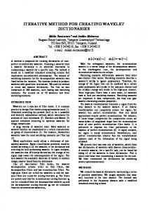
Figure 1. structure of simple layer circuit
So we profit to advantages of iterative method and FDTLM method to formulate a hybrid method that will apply in every area.
If we model this structure only with FDTLM we will be obliged to discretize all region according to the three directions (x,y,z) [JOH87] and consequently we will use more memory and that will take much more time for simulation. If this structure is modelled only with WCIP, any inhomogenity according to the third dimension will not be modelled and consequently we will simulate a model that does not reflect reality. The hybrid method resolves this problem by applying the WCIP method in the homogeneous areas and the FDTLM method in the no homogeneous areas.
1. Formulation of the Hybrid method The analysis structure is composed by planar micro strip circuit enclosed in the metallic box (Figure 1). This structure is formed by interfaces Ω separating two dielectric mediums respectively region 1 with ε1 as a permittivity and region 2 with ε2 as a permittivity.
The application of the hybrid method on the structure represented in Fig.1 consists in studying the region 2 with FDTLM method and region 1 with WCIP method. Then, to make the coupling between these two methods on the level of the interface Ω.
-1-
SETIT2009 and boundary conditions[BER 02], [PAS 00], [PAS 01] for the FDTLM.
The interface Ω is composed by the upper faces of the equivalent FDTLM symmetrical condensed nodes. In fact these higher faces of the FDTLM network represent the pixels used in WCIP
The connection between the FDTLM and the iterative method is insured by a coupling matrix. The global algorithm of the new approach is presented in Figure.3:
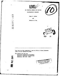
Figure 2. A node of the network FDTLM whose its higher face belongs to the interface Ω We consider the incident and reflected waves of the upper faces of the symmetrical condensed nodes of the FDTLM. These waves are reformulated using the relationship: Vi 1 and Vr1 are respectively the incident and the reflected waves in x direction in FDTLM. [JIN 92c]
V5i
Vr
and 5 are respectively the incident and the reflected waves in z direction in FDTLM. [JIN 92c] Ax and Bx are respectively the incident and the reflected waves in the x direction in WCIP. [AZI 95] Az and Bz are respectively the incident and the reflected waves in the z direction in WCIP. [AZI 95] The relationship between waves A, B and Vi, Vr on the interface is given by: Figure 3: Hybrid method algorithm
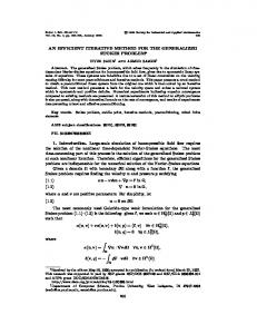
2. Validation of the Hybrid method: The second application is a demonstration of the speed of the hybrid method compared to the FDTLM method. By simulating the same structure with the two methods (FDTLM and hybrid method) and by comparing times of simulation of the two methods we will show the advantage brought by the hybrid method. The second application considered consists of a multilayer structure [12]. The fig. 4 describes the layout of a two-port vertical transition with a while aperture formed on the plane between the upper and lower strips to provide a fed-through coupling between those two strips.
Zoi is the intrinsic impedance of the two middles. It is equal to: The implementation of the global algorithm consists of establishing a recursive relationship between the waves in the two regions 1 and 2 treated respectively by FDTLM and WCIP, using the reflection operator in the spectral domain and the boundary conditions required on the interface plane for the WCIP, connection matrix[JIN 92b]
To demonstrate the efficiency of the proposed algorithm we have first simulated the structure using the FDTLM and in the second case the structure is simulated with the hybrid algorithm FDTLM-WCIP. -2-
SETIT2009 A computer program, with FORTRAN language, has been written to evaluate the S parameter matrix.
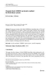
Figure.7: Simulated reflected coefficient S11 using FDTLLM method
Figure 4: Layout of the proposed vertical transition of microstrip line with an electrically wide aperture
Fig.6 shows the results of the simulation using FDTLM Fig.7 shows the results of the simulation using Hybrid method It is noticed that there is a good agreement between the calculated results and those obtained by simulation. The table below gives us the time put by the FDTLM and the hybrid method in the simulation and the number of cells, to give an idea about the memory of the machine used by the two methods.
Figure.5: Top view of the proposed vertical transition
Tab-1: Comparison between the FDTLM solution and the Hybrid FDTLM-WCIP technique regarding the computational time for the structure illustrated in Fig 9
With:
εr1=εr1=10.2 h1=h2=0.635mm
wf=0.60mm
(3)
FDTLM
Hybrid WCIP
FDTLM-
wa=4.80mm wc =1.80mm
La=4.80
Proprieties of the Computer Pentium(R)4 used for the CPU 3.20Ghz simulation
Pentium(R)4 CPU 3.20Ghz
Time of the simulation 1h 41mn 43s
15mn
Number of cells 561152
53248
50s
It is noted that our method is almost 6 times faster than the traditional method. This reduction of the computing time because of the reduction in the number of Tab-1 : Comparison between the FDTLM solution and the Hybrid FDTLM-WCIP technique
Figure. 6: Simulated reflected coefficient S11 using hybrid method -3-
SETIT2009 regarding the computational time for the structure illustrated in Fig 9 cells is considered in the simulation of the structure.
Conditions in the Frequency-Domain TLM Method and Their Application to Planar Circuits” ,IEEE Transaction on microwave theory and techniques, vol, 49, no. 8, august 2001. [TRA 03] H . TRABELSI, A. GHARSALLAH and H.BAUDRAND “An al ysi s of Microwave Circuits Including Lumped Elements Based on Iterative Method", International Journal of RF and Microwave Computer-Aided Engineering. Vol 13, Issue 4, 2003, pp 269 275.
3. Conclusion It is estimated whereas we will solve many problems by using the hybrid method which will allow us to have much more facility in modelling of the structures and especially to make simulation with a minimum of time. We succeeded in formulating a three- dimensional and fast numerical method
REFERENCES [AZI 95] M.AZIZI, H.AUBERT and .BAUDRAND,”A new iterative method for scattering problems”., 1995. European microwave conf, proc, vol.1,pp 255-258. [BER 02] J.P. BERENGER,”Application of the CFS PML to the absorption of evanescent waves in waveguides” Microwave and Wireless Components Letters, IEEE Volume 12, Issue 6, June 2002:218 – 220. [GHA 01] A. GHARSALLAH, A. GHARBI and H. BAUDRAND, "Efficient analysis of multiport passive circuits using the iterative technique". Electromagnetics,21:73-84, 2001. [JIN 95] Hang JIN and Ruediger VAHLDIECK “A New frequency- Domain TLM Symmetrical Condensed Node Derived Directly from Maxwell’s Equations”.IEEE MTTS-S Digest 1995. [JIN 92a] Hang JIN and Ruediger VAHLDIECK, “Calculation of frequency-dependent S-parameter of CPW air-bridges considering finite metallization thickness and conductivity,” 1992 IEEE 1nt.Microwave Symp.Dig., Albuquerque, June 1-5, pp207-210. [JIN 92b] Hang JIN, R.Vahldieck ”The frequency-domain transmission line matrix method : a new concept“,IEEE Trans. Microwave Theory and Technique. vol. 40, no12, 1992; pp. 2207-2218. [JIN 92c] Hang JIN and Ruediger VAHLDIECK,“The frequency- domain transmission line matrix method – A new concept,” IEEE Trans. Microwave Theory Tech., vo1.40, pp.2207- 2218, Dec. 1992 [JOH87] P.B. JOHNS, ”A symmetrical condensed node for the TLM method” IEEE Trans. Microwave Theory and Techniques”, vol. 35, 1987, pp. 370–377. [PAS 00] D. PASALIC, J. BORNEMANN and R. VAHLDIECK, "Absorbing boundary conditions in the frequency-domain TLM method and their application to planar circuits", IEEE Trans. Microwave Theory and Tech., vol. 18, no. 12, pp. 2176-2186, December 2000.
[PAS 01] Damir PASALIC, Jens BORNEMANN, and Rüediger VAHLDIECK, ‚”Absorbing Boundary
-4-