JUST-UI: A USER INTERFACE SPECIFICATION MODEL Pedro J. Molina Santiago Melia and Oscar Pastor∗ Abstract
A Model for the Specification of Abstract User Interfaces based on Conceptual Patterns is proposed to enhance the semantic captured by an object-oriented analysis method. The model gathers both Presentation an Navigation issues. A graphical notation is also provided to make easier the specification tasks. This simple graphical notation allows that a non analyst can understand and participate in the specification process.
Keywords: model based user interface specification, conceptual modelling, user interface requirements.
1.
Introduction
In this new millennium, the volume of data produced in the Information Society is increasing continuously on a daily basis. In this data ocean, tools for searching and navigating among data are really needed as never before to extract valuable information. On the other hand, better applications in less time are demanded. Nevertheless, developing good UIs for such Information Systems is a non trivial task which requires effort to build and maintain them in order to assure a good quality product. Commercial business applications based on Information Systems have similar interfaces, mainly based on forms. Just-UI tries to identify patterns in such UIs and abstract them to work in terms of the problem domain. The model is based on Conceptual Patterns to capture elemental UI requirements such as: how to search?, how to order?, what to see?,
∗ P.J. Molina and S. Melia ({pjmolina|smelia}@care-t.com) work at CARE Technologies (a R&D company) in Denia, Spain. O. Pastor (
[email protected]) work at the Dept. of Information Systems and Computation at Valencia University of Technology, Valencia, Spain.
1
2 and what to do? Answering these questions in an abstract specification allows us to express the requirements without fixing any target environment. Design aspects, deliberately, are not collected in this phase in order to maintain the specification free of any design issues. The paper starts with the motivation and introduces the concepts used in the Just-UI approach. Following, a graphical diagram based on these concepts is introduced. Then, a case study and generation issues are commented on. Finally, conclusions are given.
2.
Motivation
Traditional UML CASE tools such as Rational Rose[16], Together[20] or Argo[22] do not explicitly consider the specification of UIs. Therefore, specification with these tools is very complex and incomplete[14]. Collections of UI Patterns do exist. However, these collections are focused on design problems[19, 23] and not on analysis problems. Indeed, surveys on MB-UIDEs[18, 15] show that patterns at analysis levels are unexplored in classical MB-UIDEs. The work here presented tries to bring UI Specification nearer to non analysts (users, graphical designers, etc) with the ultimate intention of involving them in the process of specification.
3.
The Just-UI approach
Our contribution is focused on Just-UI: a Model for the specification of UIs linked to Conceptual Modelling and code generation techniques to automatically implement the UI for business applications. Constantine et al.[6] proposes a technique to gather UI requirements prototyping with users using paper and Post-Its. In this technique, each Post-It represent an interaction unit (e.g. form or web page in the implementation). The user and analyst build together the navigation among interaction units drawing arrows. Just-UI follows the same intuitive approach to describe UIs as it is used in [6] and Ruble [17]. The Conceptual Modelling stage is supported by an object-oriented method, the OO-Method[12], to obtain a conceptual schema of an Information System. OO-Method is a method that provides UML[5] compliant diagrams and is based on the formal language OASIS[11]. The model captures classes, properties for classes: attributes, services (methods), static, and dynamic constraints, etc. following a classical object-oriented approach. Just-UI extends OO-Method to capture User-Interface requirements to explore and navigate among data (information objects). The final goal is to collect interface requirements in an abstract way and to auto-
Just-UI: A User Interface Specification Model
3
matically generate the final UI to different target environments such as Web, Windows, X11, UMTS, or PDAs. The UI requirements captured by this approach are collected in the OO-Method Presentation Model. The following subsections describe the patterns used.
3.1
Simple patterns
Simple patterns are single components that can be asked directly to user or customer by an analyst. These simple concepts constitute the primitive bricks to build the UI.
Filter. A filter is a criterion that is useful for searching for objects. Fixing a class, the user needs to search for objects satisfying a given condition. E.g. searching cars by fare or colour in a Car Rental Service. The analyst has identified the Vehicle class in the problem domain. Now he has to ask the user: How do you need to search for Vehicles? Each answer from the user constitutes a filter criterion. E.g. the formula for searching red cars with special fare is: colour="red" and fare.code="special" Query By Example techniques [26] could be applied too, but previous experiences reveal us that, in general, users do not need a powerful search engine. Specific filters tailored for the current tasks increases the usability. Order Criterion. After gathering search requirements, the analyst can inquire: How must objects be ordered?, alphabetically?, by colour? Again, each response given by our customer constitutes an Order Criterion Pattern. Order Criteria can be specified in terms of a list of attributes defined in the conceptual schema and an ordering direction for each attribute: ascendant or descendent. The semantic associated with this pattern is: sort the collection of objects using the criteria expressed in the list. E.g. to sort Vehicles by brand (ascending) and colour (descending), we have to express: brand ASC, colour DES Display Set. At this point, we have the objects filtered and ordered. But, what properties does the user need to see from a given object? The customer could answer for a Vehicle: I need to see: brand, model, year, colour, state, location, and price per day. A list of visible attributes from the given class is enough to capture the initial user requirement. E.g. the Vehicle Display Set example could be: brand, model, year, colour, state, location, fare.price per day
4 Up to now, the user has filtered, ordered and listed the objects. At this point, the user has enough power in the UI to search and select objects. In an object-action (noun-verb) paradigm the first step is to select the object to interact with. Once the object is selected, the second step can be proposed: What to do with such an object? Basically, two responses can be provided: To show information related to this object (Navigation). To execute methods to change the object’s state (Action). Note that Navigation is merely observation and it is innocuous by definition. Nevertheless, Actions may execute services or operations that could alter valuable data.
Navigation. Following with the analyst’s questions to users, the next one to ask is: When you have reached a Vehicle, do you need to see any other related information? E.g.: The user is exploring a Vehicle. The analyst has identified the need to navigate to additional information such as Contracts and Fare. Beyond this kind of navigation, the analyst is refining aggregation or inheritance relationships between classes in the conceptual schema. The analyst must specify the subset of objects to be reached in the target. E.g. it can be expressed using roles of relationships, or filters. Actions. The second kind of semantic associated to an object is the possibility of changing the state of the current object. In conventional object-oriented methodologies, this is performed executing methods (or services) defined in the class. Once again, in a given context, the analyst has to ask the user: What actions the object can suffer? The user can answer something like this: In the fare scenario I need to work with fares for vehicles: I need to create, modify, and destroy fares. Additionally, I need to change the fare related to vehicles. With this information, the analyst has enough clues to complete the conceptual schema with new services in classes and to organize a subset of services to offer users in a given scenario. This list (ordered subset) of visible services is the representation of what we call Offered Actions Pattern.
3.2
Building complex patterns
An interaction unit is a particular scenario in the UI where users have to interact with them in order to carry out concrete tasks. The Presentation Units[2] abstract these contexts as a set of AIOs[4] (Abstract Interface Objects) discarding design issues.
Just-UI: A User Interface Specification Model
5
A reduced set of patterns focused on Presentation Units have been abstracted based on literature review[6, 17], our experience exploring UIs of commercial applications and developing business applications. These patterns are going to be referred to as Presentation Patterns. The Presentation Patterns are used to abstract interaction units with common behaviour. This approach provides different advantages: Extensibility: new Presentation Patterns can be included in the model. Homogeneity: every interaction scenario is expressed with a Presentation Pattern. Design independence: no design details are collected in the model. At this stage, we have identified four types of Presentation Patterns: Service (interaction with service execution), Instance (interaction with an object), Population (interaction with a set of objects), and MasterDetail (composed interactions).
Service Presentation Pattern. Service Presentation Pattern is in charge of modelling a dialogue to deal with a service. The user must provide the arguments and launch the service. In the problem domain, the analyst identifies a service associated with a certain class: e.g. to create a contract in the Car Rental Service and declares it in the object model. In terms of specification, the Service Presentation Pattern encapsulates the interaction unit to supply a service in the interface. In this context, the service specification can be completed asking the user: What input data are needed for this service?, How must input data be grouped?, Are the input fields inter-related?, What kind of feedback do you need for each selected object?, etc. Many answers to this questions can be expressed using other auxiliary simple patterns: introduction (constrains the introduction of values), defined selection (defines by enumeration the valid values), population selection (expresses how to select objects), dependency (expresses dynamic interdependencies among objects), supplementary information (provides extra feedback for object identifiers), Status Recovery (recovers argument values from attributes), and grouping (logical grouping of arguments). For further references see [13, 10]. Instance Presentation Pattern. Its mission is to model the data presentation of an instance and support interaction with it. It is oriented to object manipulation. In terms of the user, the Instance Presentation Pattern arises out of the necessity to observe single objects. In addition,
6 the user may want to change the state of the object (by means of services) and to navigate to related objects. In the problem domain the analyst identifies a certain class, e.g. Vehicle. Once the class is defined, he could ask the user the following questions: Which attributes of the object do you wish to view? What actions can be done on the object? Which additional info. (relationships) do you want to reach in the interface by navigation? The specification of the Instance Pattern is defined using three of the simple patterns: A Display Set (what properties to show), Actions (what services could be executed for the instance) and Navigation: (the links to the inheritance and aggregation relationships which it is desirable to navigate to from this instance). In OVID[21], the concept of view plays a similar role to the Instance Presentation Pattern.
Population Presentation Pattern. This pattern models units of interaction focused on showing sets of instances of a class. This pattern deals with the necessity of working with object collections. It is composed of five smaller patterns: Filters (how to search), Order Criterion (how to order), Display Sets (what to show), Navigation (how to navigate from an object), and Actions (what can be executed on objects). In the problem domain, the analyst, as in the previous case, identifies a class with its attributes, services and relationships. Later, he can ask the user to identify these smaller components bricks. Master-Detail Presentation Pattern. The last pattern models more complex units of interaction dealing with master/slave presentations. For this reason, the components are divided in two logical types; Master and Detail components. These components are related by means of an aggregation relationship crossed in a given direction: from master to detail. Therefore, when a Master Component changes, the Detail Components associated also do. In business applications, this pattern is very usual. E.g. an invoice and the possibility of introducing the lines of this invoice in the same scenario. In order to specify them, the analyst has to detect and create the classes, the elemental components, and finally the Master Detail Unit. The Master component can be an Instance Pattern (it will display an object) or a Population Pattern (it will display a collection of objects). The patterns that act as Detail Component can be of several types: an Instance Pattern if the role path is univalued, a Class Population Pattern if the role path is multivalued or a Master/Detail Pattern as well, which makes it possible to have, recursively, more depth levels in
7
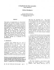
Just-UI: A User Interface Specification Model Instance1
Population1
Alias1
MasterDetail1
Alias2
(a) Instance Pattern
(b) Population Pattern
Figure 1.
Alias3
(c) Master/Detail Pattern
ServiceNew
Alias4
(d) Service Pattern
(e) Navigational Link
Navigational Diagram: Graphical primitives.
the master/detail. The specification of the Master/Detail Presentation Pattern is expressed by means of the following concepts: Master class, Presentation Pattern acting as a Master, Role path (side of an aggregation relationship) visible of the Master class that acts as a detail and Presentation Patterns like Details.
3.3
System Access
Finally, the user needs entry points to the interface in order to access the UI. To deal with this type of requirement, a tree structure is used to organize the access to interaction units: the Hierarchical Action Tree (HAT)[8]. This abstraction provides a tree for specifying how the user can access the system. Each intermediate node of the tree acts as a container with a label. Each leaf node contains a label and a link to an interaction unit. This data is automatically mapped in the implementation phase to menus (in windows environments) or pages and links (in web environments). Using a tree structure is a good technique to support the Gradual Approach Principle[7]. For further references, see [8].
3.4
Navigational Diagram
Once the concepts have been introduced, a Navigational Diagram is going to be presented as a graphical representation of the stated concepts. Diagrams provide a more suitable workspace to deal with large projects and makes it easier to understand and edit the UI specification. The proposed diagram is a directional graph were nodes constitute Presentation Patterns (represented as boxes) and arcs represent navigational links between a pair of Presentation Patterns (represented as arrows). Figure 1 shows the representation of each concept. An example of the Navigational Diagram can be shown in Figure 3. The diagram shows the scenarios specified to be present in the UI and the navigational relationship among them. The specification editing tasks could be very easy if a graphical editor for diagrams is available. A pro-
8 Has
0..*
Contract
+Open Contract 0..1
+Old Contracts 0..*
1..1 Customer
1..1
Has
Vehicle 1..1
Figure 2.
0..*
Fare 1..1
Class diagram for the Rent-a-car Schema.
totype of the editor (Just-UI/VISIO) has been built programming in the VISIO[24] environment. In Just-UI/VISIO, the left part of the window contains a component palette (called Stencil in VISIO terminology) and the right part of the window contains the drawing zone (work-area for diagrams). The user can select presentation pattern components on the palette and perform a drag and drop operation over the drawing zone.
4.
A Case Study: Rent-a-car
A brief case study based on a Rent a Car business system is going to be introduced. The example manages information about customers, vehicles, fares, and contracts. The classes of the Conceptual Schema of the quoted system are shown in Figure 2. The first step involves gathering the UI requirements from the customer explanations about the system. Once completed, the patterns identified in the process are shown. Initially, the user wants, as an entry point, a scenario capable of searching and showing the vehicles the company owns. Therefore, the user requires to search for vehicles with a contract associated to them. Next, the customer wants to select a vehicle and see the current contract associated in a scenario where vehicle and contract are displayed. In such a scenario, it will be possible to launch the operations rent and return. It will also be possible to select a vehicle to show the old closed contracts with theirs related customers and to launch operations on such customers as change address, or delete. Finally, the user wishes to see the related fares for each vehicle and the possibility of maintaining them (operations: create, change and delete). With these requirements expressed in natural language, the analyst can identify some patterns in the interface (see Navigational Diagram shown in Figure 3): The first scenario can be modelled as a Population Presentation Pattern for class Vehicle where a filter is defined to search for vehicles that have a current contract. In such a scenario, the user can
9
Just-UI: A User Interface Specification Model MD_Contract-Vehicle
S_Rent Rent Vehicle
Current Contract-Vehicle
S_Return Return Vehicle
P_Vehicle
P_OldContracts
Vehicle Fleet
Old Contracts
S_Change_Address I_Customer
Change Address
Customer
S_Delete_User Delete User
S_Create_Fare Create Fare I_Fare
S_Change_Fare Change Fare Fare S_Delete_Fare Delete Fare
Figure 3.
Navigational Diagram for the Rent-a-car Schema.
browse a Master/Detail Pattern containing a Vehicle Instance Pattern as Master component and a Contract Instance Pattern as Detail component. The Master component also provides a set of Actions to reach rent and return operations. A navigation is identified from Vehicles to another Contract Population Pattern crossing over the aggregation relationship old-contracts. In this scenario, the user can jump again to a Customer Instance Pattern and select operations: change address or delete. Finally, the analyst can add a navigation from the Vehicle scenario to Fare Instance Pattern. In this pattern, three operations are allowed: create, change, and delete fares.
5.
Generating the User Interface
The specification collects the UI requirements expressed in terms of the problem domain. It constitutes a good documentation of the system itself. This specification can be also used to generate code in order to implement the UI for the Information System. Depending on the target platform, different translations must be done. In CARE Technologies S.A. we have developed translators to produce automatically such UIs. For the moment, we have developed translators for the following target languages (and platforms): Visual Basic (Windows), Java (Swing), JSP, ASP, and ColdFusion (Web pages). Depending on the target environment, a different style guide is used to obtain a homogeneous UI with respect to other applications. Each pattern in the Model can be expressed in terms of AIOs[4] (Abstract Interface Objects). In the translation phase these AIOs are
10 mapped to CIOs (Concrete Interface Objects, controls or widgets) following a table of transformations based on ergonomic rules[3, 9]. The implemented system is assumed to use an n-tier architecture. The UI layer acts as a client of a Business-Logic layer acting as a server in a client-server paradigm. Therefore, the UI contains the code to make calls to the Business-Logic layer: the responsible for executing the services and maintaining the consistency of the data. Code for error trapping is also produced to isolate the UI for any potential failure that could occur in communications or other layers.
6.
Conclusions
A model for the specification of UIs based in Conceptual Interface Patterns and a graphical notation has been presented. Just-UI provides a set of patterns that can be used as building blocks to create UI specifications for Information Systems. The whole concepts used are located in the problem domain, thus allowing an easy matching of requirements to the UI model. Analysts can create complete specification with very little effort. Besides, graphical designers can model without needing to be expert analysts. Users can also understand and review the navigational diagrams with analysts in order to validate the UI specification. The specification obtained with Just-UI is platform neutral. The specifications do not contain any design details. In this way, the specification is reused to provide similar UIs across several target platforms. At the same time, the concepts used have direct translation to the final implementation. Each presentation pattern is reified (mapped) to windows, forms, web pages or any other implementation of presentation unit that can be presented in the solution domain. The need to obtain tailored UIs depending on the final platform (for example PDAs or UMTS devices) is beyond the scope of this paper, but this can be naturally achieved by providing design tools for specific environments capable of refining the initial Just-UI specification to add and maintain such design topics. Using Just-UI to specify the User Interface in conjunction with OOMethod to gather the functionality of the system, opens the door to automatically obtaining complete prototypes of Information Systems, copying with Data Persistence, Business-Logic, User Interface and User Help. If the specification is complete enough and non ambiguous, more and more code could be generated as final application code without additional manual changes. Therefore, the maintenance phases of software can be moved from code to specification as it was stated by Balzer in the Automatic Programming Paradigm[1].
References
[1] R. Balzer, T.E. Cheatham, and C. Green, Software Technology in the 1990s: Using a New Paradigm, IEEE Computer, Nov. 1983, pp. 39-45. [2] F. Bodart et al., A Model-Based Approach to Presentation: A Continuum from Task Analysis to Prototype. Proc. of the Eurographics Workshop on Design, Specification, Verification of Interactive Systems, Carrara, Italy, June 1994, Focus on Computer Graphics, Springer-Verlag, Berlin, pp.77-94. [3] F. Bodart and J. Vanderdonckt, On the Problem of Selecting Interaction Objects Cockton G., Diaper S.W., Weir G.R.S (eds), People and Computers IX (HCI‘94), Cambridge University Press, 1994, pp 163-178. [4] F. Bodart and J. Vanderdonckt, Widget Standardisation through Abstract Interaction Objects, Institut d’Informatique, Facult´es Universitaires Notre-Dame de la Paix. Namur, Belgium. 1996. [5] G. Booch, J. Rumbaugh, and I. Jacobson, Unified Modeling Language (UML summary). Version 1.0, Rational Software Corporation, January 1997. [6] L. Constantine and L. Lockwood, Software for use. A practical Guide to the Models and Methods of Usage-Centered Design. Addison Wesley, 1999. [7] IBM, Object Oriented Interface Design: IBM Common User Access Guidelines. Que, Carmel, Ind. 1992. [8] E. Insfran, P.J. Molina, S. Mart´ı, and V. Pelechano, Ingenieria de Requisitos aplicada al modelado conceptual de interfaz de usuario (Requirements Engineering Applied to User Interface Conceptual Modeling) [In Spanish]. In Proceedings of IDEAS’2001, pages 181-192, Santo Domingo, Heredia, Costa Rica, April 2001, Ed. CIT. [9] P.J. Molina, Master Science Thesis. Especificaci´ on de Interfaz de Usuario en OOMethod (User Interface Specification in OO-Method) [In Spanish] DISC, Technical University of Valencia, Valencia, Spain, 1998. [10] P.J. Molina, O. Pastor, S. Mart´ı, J. Fons, and E. Insfran, Specifying Conceptual Interface Patterns in an Object-Oriented Method with Code Generation. In Proceedings of UIDIS’2001, pages 72-79, Zurich, Switzerland, May 2001, IEEE Computer Society.
11
12 [11] O. Pastor, F. Hayes, and S. Bear, OASIS: An OO Specification Language, Proc. of CAiSE-92 (Conference), Lecture Notes in Computer Science 593, Springer-Verlag, 1992, Manchester (UK), pp. 348-363. [12] O. Pastor et al., OO-METHOD: An OO Software Production Environment Combining Conventional and Formal Methods, In Proceedings of 9th International Conference, CAiSE97, Lecture Notes in Computer Science 1250, Springer-Verlag, June 1997, Barcelona, Spain, pp. 145-159. [13] O. Pastor, P.J. Molina, and A. Aparicio, Specifying Interface Properties in Object Oriented Conceptual Models., In Proceedings of Working Conference on Advanced Visual Interfaces, AVI 2000, Palermo, Italy. Ed. ACM, May 2000, pags. 302-304. [14] P. Pinheiro da Silva and N.W. Paton, User Interface Modelling with UML. 10th European-Japanese Conference on Information Modelling and Knowledge Representation, Saariselka, Finland, May 2000. [15] P. Pinheiro da Silva, User Interface Declarative Models and Development Environments: A Survey. In Interactive Systems: Design, Specification and Verification (7th International Workshop on Design, Specification and Verification of Interactive Systems), Limerick, Ireland. LNCS Vol.1946, pages 207-226, Springer-Verlag, June 2000. [16] T. Quarani, Visual Modeling with Rational Rose and UML. Addison-Wesley, 1998. [17] D.A. Ruble, Practical Analysis and Design for Client/Server and GUI Systems. Yourdon Press Computing Series, 1997. [18] P. Szekely, Retrospective and Challenges for Model-Based Interface Developmnet In Computer-Aided Design of User Interfaces, pages xxi-xliv, Namur, Belgium, 1996. Namur University Press. [19] J. Tidwell, Common Ground: A Pattern Language for Human-Computer Interface Design. http://www.mit.edu/~jtidwell/common\_ground.html, 1999. [20] TogetherSoft, http://www.togethersoft.com. [21] D. Roberts, D. Berry, S. Isensee, and J. Mullaly, Designing for the User with OVID: Bridging User Interface Design and Software Engineering, MacMillan, 1998. [22] J. Robbins, D. Hilbert, and D. Redmiles, ARGO: A Design Environment for Evolving Software Architectures. In Proceedings of ICSE’97, pages 600-601, Boston, MA, May 1997. ACM Press. [23] M. Van Welie, The Amsterdam Collection of Patterns in User Interface Design. http://www.cs.vu.nl/~martijn/patterns/index.html, 2000. [24] Microsoft Corp, VISIO http://www.microsoft.com/visio. [25] M. Zloof, Query-By-Exaple: A Data Base Language. IBM System Journal. Vol 4, pages 324-343. December 1977.


![DTT User Interface Specification - SABC [PDF]](https://m.moam.info/img/260x300/dtt-user-interface-specification-sabc-pdf_6479ecc7098a9ee37d8b46a7.jpg)