Define an LCF coded group Щ as one layer, and V as the num- ber of layers per ..... [8] V. Tarokh, N. Seshadri, and A. R. Calderbank, âSpace-time codes for high ...
LAYERED SPACE-TIME COMPLEX FIELD CODING: FULL-DIVERSITY WITH FULL-RATE, AND TRADEOFFS Xiaoli Ma and Georgios B. Giannakis Dept. of Electrical and Computer Engr. Univ. of Minnesota, Minneapolis, MN 55455 2. SYSTEM MODEL
1. INTRODUCTION Rapid increase of cellular service subscribers and wireless applications has stipulated tremendous research efforts in developing systems that support reliable high rate transmissions over wireless channels. However, these developments must cope with challenges such as multipath fading, as well as bandwidth, and power limitations. Multi-antenna systems on the other hand, allow for a significant increase in the capacity of coherent wireless links, when communicating over flat Rayleigh fading channels [4]. Various multi-antenna designs have been developed targeting either high-performance, or, high rate; e.g., VBLAST [10], and DBLAST [3]. Recently, designs enabling desirable performance-rate tradeoffs receive increasing attention; those include combining array processing with space-time coding (STC) [9], threaded space-time (TST) coding [5], precoded layered space-time coding [11], to name a few. However, none of these existing schemes achieves full diversity and full rate simultaneously. In this paper, we design a layered space-time scheme equipped with linear complex field (LCF) coding, which enables full diversity and full rate (FDFR). We will abbreviate it as FDFR-LCF, our design STC. When the number of transmit-antennas is � subsumes the design in [2] as a special case. We also delineate the performance-rate tradeoff when low-complexity sub-optimal decoding is performed. Notation: Upper (lower) bold face letters will be used for matrices (column vectors). Superscript À will denote Hermitian, and � transpose. We will reserve for the Kronecker product; and diag � will stand for a diagonal matrix with � on its main diagonal.
� ��
� �
�
0-7803-7551-3/02/$17.00 ©2002 IEEE
���
.. .
.. .
� ��
��
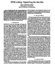
Fig. 1. MIMO model
������ � � �� �� ������ � � � � ��� �� � � � ��� � where � is the number of groups. The LCF encoder �� � �� per group is an � � � matrix with entries drawn from the complex field. Each sub-block � is coded linearly (via � ) to obtain a coded sub-block as: � �� � � (hence the term LCF). Define an LCF coded group � as one layer, and � as the number of layers per information block. Concatenating �� � �� we obtain the � � � block � which contains all the LCF coded symbols from �. Every � � � block � is further mapped to � blocks �� � �� of size � � �, with each block � transmitted through the �th antenna. Each LCF coded symbol in � will be transmitted through one transmit antenna per time slot. be the flat fading channel associated with the �th Let � transmit-antenna, and the th receive-antenna. We assume that � ’s are independent and time-invariant during � symbol periods. The th sample at the receive-filter output of the th antenna are drawn from a fiThe information bearing symbols so that nite alphabet � , and parsed into blocks of size � � . Every block � is split in sub-blocks �� , each of length ��� . Hence, (groups) �� ��� ��� � , �� � �
�
���
���
�
�
�
� �
�
�
�� � � �
�� � �
�
�
�
��
can be expressed as:
� � � �
� �
��
���
� � � �� � � ��� � ��
� �
(1)
�
where is complex additive white Gaussian noise (AWGN) � at the th receive-antenna with mean zero, and variance . If the LCF-ST coded symbols transmitted per time slot from the � transmit-antennas are given by:
�
� � � � ��� � � � � ��� ��� ��� � � � ��� �
�
�
The work in this paper was supported by the NSF Wireless Initiative Grant No. 9979443, the NSF Grant No. 0122431, and by the ARL/CTA Grant No. DAAD19-01-2-011.
�
LCF Encoder
��
��
LCF-ST Decoder
Multi-antenna systems allow for a significant increase in the transmission rate of coherent wireless transmissions over flat Rayleigh fading channels. Various multi-antenna designs have been developed in recent years targeting either high-performance, or, high rate. In this paper, we design a layered space-time (ST) scheme equipped with linear complex field (LCF) coding, which enables full diversity with full rate, for any number of transmit- and receiveantennas. Furthermore, we delineate the tradeoff between diversity and rate in the class of layered ST schemes, when sub-optimal decoding is employed. Our theoretical claims are confirmed by simulations.
Space Time Encoder
ABSTRACT
�
�
.. .
� �
.. .
� �� � � �� �
� ��� � � � � �� � � ��� � � � � �� � .. .
.. .
��� � � � then the matrix counter part of (1) over � time slots is � � �� � ����
442
��
��
��
�
(2)
(3)
where the
� � ��th entry of � is �
��
For simplicity, we assume here that the � � flat fading channels are independent and identically distributed (i.i.d.). Using average pairwise error probability analysis, it follows that the maximum diversity order is ��� � � (see e.g., [8]). As it takes
time slots (size of �� ) to transmit symbols (size of �), our transmission rate is: symbols per channel use (pcu), while the maximum possible transmission rate is ��� � symbols and ��� pcu, since we have � transmit antennas. We call ���
as full diversity and full rate, respectively. VBLAST achieves full rate ��� but loses diversity, while LCF-STC in [12] achieves at rate symbol pcu, for any � . In full diversity ���
this section, we will present a design we term FDFR-LCF-STC, which guarantees full rate and full diversity, simultaneously, for any number of antennas.
� � �� � � � ��� �
�
�
�
�� �
�
���
�
Define the spatial span of each layer as the number of columns of the ST matrix � which contain one or more of this layer’s symbols. And the temporal span as the number of rows of � which one layer’s symbols are present. For example, VBLAST in [10] has spatial span one, while LCF-STC proposed in [12] has only one layer with spatial span � , and temporal span � . Based on these two definitions, we will introduce two lemmas that provide necessary conditions for achieving full rate with full diversity.
�
��
��
��
�
�
���
�
The LCF-STC scheme introduced in [12] has full spatial span ( � ), and enough temporal span ( � ). VBLAST [10] on the other hand, does not have enough spatial span. The high rate (HR) LCF-STC proposed in [11] does not have full spatial span per layer, because only some of the transmit-antennas are conveying each layer’s symbols. Therefore, full-diversity cannot be achieved ). with HR-LCF-STC, except for the single layer case ( �
�
��
� ��
�
� �� � � ��� � �
��
�
�
�
the subscripts in (4), we observe that the layers are arranged in a row circular fashion, similar to the design reported in [5]. As per Lemma 2, the ST matrix in (4) enjoys full transmission rate ��� � symbols pcu. From the structure of � , it is evident that each layer has full spatial span ( � ), equal to the temporal span ( � ); hence, Lemma 1 is satisfied, and the ST matrix in (4) could potentially enable full diversity ��� � �.
�� Recall that � depends on �� ��� , and �� �� �� . To � guarantee full diversity, we need to design �� � such that for � �� any two symbol blocks � and �¼ [8]
�
�� �
� � �� � � � � � �
� �� � ¼ � �� � �� �� �¼ �
(5)
Relying on the algebraic tools used in [6, 12], we will show that (5) is ensured � , when the LCF encoders are selected as:
��
��
� � � �� �� � ��� � �� �
(6)
�
� is to be designed, and � is a unitary Vandermonde matrix � �� � � � �� �� � �. �.� � � � �� . � �� (7) .. � .. .. � � � � � � � with generators �� � �� selected as in [6,12]. As we will see, this design of �, and the selection of � are not the only ones satisfying (5). Define ��� � as the ring of Gaussian integers, whose elements are in the form of � �� with �� � � �. For simplicity, we define �� �� � � ¼ , �� �� � �¼ , and �� �� � �¼ . We can then where
� ��� �
� ��� �
�� ��
�� ��
��
�� � �
�
�
�
�
� as [c.f. (4)] express the determinant of �
� ��� � �
� ��
Lemma 2 (Necessary condition for full rate) For an LCF coded ST matrix � to achieve full rate of ��� � � symbols pcu, one needs to guarantee that � , where is the is number of time slots number of information symbols, and required to transmit the information symbols.
�
��
�
Lemma 1 (Necessary condition for full diversity) For one LCF coded layer in � to achieve full diversity ��� � � , each
layer must have full spatial span ( � ), and enough temporal span ( � ).
� ��� �
� � � �� �� � � � � � � �� � � (4) .. .. .. . . . ��� � � ��� � � � �� �� � where � � � denotes the th element of the �th layer. Checking
3.1. Encoding
�
� ��� �� ���
� �
3. FRFD-LCF-STC DESIGNS
�
� � ��� �� � ��� ��� �� ���
ST matrix � as
� .
�
� �� � �
� � ��� ��� �
�
� � � �� ��
���
��� ��� ��� �
�
(8)
��
�� � � � � � � � is one permutation of the sequence ��� � � � � � �, � ��� � � � � � � � is the number of inversions of the sequence ��� � � � � � � �, and � � � is defined as in (2), corresponding to � � � � in (4). Since � �� � � , we have � � � � � � � � , where
is the th row of �. At this point, we will need the following
where �
��
�
��
�� � �
��
�
� �
�
�
� �
��
�
result proved in [12].
Although LCF-STC in [12] enables full diversity, it can not achieve full rate, because only one antenna is used per time slot. Similarly, DBLAST in [3] has the potential to collect full diversity, while the rate is reduced by the “all-zero wedges” that are present in its ST matrix, and by the redundancy introduced by (Galois Field) channel coding. To achieve full rate with full diversity, the designed ST code has to satisfy Lemmas 1 and 2. Towards this objective, let us now select the block length � �, � , and let each sub-block (and thus each layer) have length for a total of � � layers. For FDFR, we design the � �
�
� ��
�� � � ��
�� �
Lemma 3 If the constellation of �� is carved from � , then �� �� �� has no zero there exists a matrix � which guarantees � �� �. Furthermore, the entries of � �� belong to entry when � � .
�� �
�
��
Based on Lemma 3 and the algebraic tools in [6, 12], we can directly select � identical to that used in the non-high rate LCFSTC scheme used in [12]. For an � � matrix � chosen ac�� becomes a polynomial in with cording to Lemma 3,
� � �
443
� ��
�
�� ���
degree � � . Note that the coefficients of this polynomial � �
� � . Since �� � ��� � [c.f. Lemma 3], we are � � � � ��� �� � have that ��� � � ��� � . Therefore, by using Lemma 3 again, we can design such that �� , � �¼ . , Comparing (2) with (4), we have that when �� ��
� �� �
�
� �� �� �
� � � �� � �� � � � � �� � � � � �� �� � �� � �� � � ��� � �� Thus, � � � �, or, � � �. It can be verified that �
�
�
�
�
�
� � � � �� � � � � � � ��� �
�
3.2. Decoding In the following, we will introduce near-optimal (in the maximum likelihood (ML) sense), and sub-optimal decoders for our full rate full diversity design. Let us define the th column of � in (3) as �� , and stack � columns of � to a super vector � . We can then rewrite (3) as
�� � � � � �� �� � � ��
� � �� ��
�
.. .
�
�
(9)
�
� � � � � � � � ��
���
��
���
��
� �
���
��� � �� � �� � � �� ���
��
���
(10)
Thanks to the structure of (4), we have shown that the power
� in � ��� � is a multiple of � ; i.e., � ��� � is a polynomial � with degree � �. Therefore, instead of designing a � according to Lemma 3 for the dimension � �� ��, we can just design � directly. Interestingly, the design of � guarantees diversity of order � . Thus, we do not need to design a new � . � can be selected as any of the generators �� � �� for �. This � � design subsumes [2] where � � �� is selected. It also confirms of in
�
��
�
�
��
�
��
�
the non-uniqueness of the FDFR design, and offers flexibility to maximize also the coding gain. Summarizing our derivations so far, we can establish the following proposition:
�� �
Proposition 1: For any constellation of �� carved from � , there � � exists at least one pair of � for which �� � � guarantee (5), and thus enable full diversity ST transmission in (3). The design of � is the same as that of [6, 12] for dimension � , and can be selected as � th root of any generator for �.
� � ��
�
where the permutation matrix � , and the diagonal matrix �� are defined, respectively, as
� � � � �� � � �� � � �� � diag��� �� � � � � � �� � �� �
and �� is the th row of �. By defining unitary matrix
�
��
�
�� �
�
� ��
�
� ���� � ��� � �
� �
�
�
�
�
�
�
� �
�
�
� ��
�
¢
(11)
� � �
� �� � � �
� � � �
� � � � � ��� � � � � � �� � � � ��� � � � � � �� � �
�� ����
� �� ��
��� ��
���
��
���
� �
��
��
��
�
�
� �
��
�
�
�� �
� �
��
(12)
� ��� � is a polynomial � � � �� , � ��� ,
Given � in (11) and based on Lemma 3, in �� with coefficients in � . If we select ��� or, � � , then (5) is guaranteed.
� �
��
���
� �
�
�
�� �� � ���
(14)
Now we can use sphere decoding or semi-definite programming algorithms to estimate � based on (14). The decoding complexity � depends on the length of �, which here is � � . When is large, the decoding complexity is high even for near-optimal decoders. Based on (3) and (4), for the th time slot, we have
���
��
� � �
� � �� � � � �� � � �
�
�
�
.. .
�
(15)
��
Using (6), we find that ��
.. .
� � �� �
� ��
� ���� � � � ���
�
��
we obtain
as an application example of In the following, we will use � , we select Proposition 1. According to [6], when �
�� � � � ��� �
�� � � � , and the
� � � � �� � �� �� �
�� � �
�
��� � �
where ��� is the th column of � . Based on (4) and (6), we obtain
�� � � � � � � �,
Therefore, we obtain that for each permutation �
(13)
��
��
���
�
��
� �
�
�
��
where � � � �� . For a sub-optimal decoding alternative inspired by the nulling-cancelling algorithm [10], we follow these major steps (see also [11]): step 1) (nulling:) Based on (15), perform QR decomposition for each ; step 2) (sphere-decoding:) Supposing the current layer is the th layer, use sphere-decoding to decode it; step 3) (cancelling:) Cancel the th layer from all the other layers, then go to step 2) for st layer.
�
�� ��
�
3.3. Simulations
� ��
�
and varying � , we compare our FDFR deSelecting � sign with the LCF-STC in [12], and the ST orthogonal designs (ST-OD) in [1]. To maintain the same transmission rate, we use -QAM for LCF-STC and ST-OD, and -QAM for our FDFR scheme. The LCF encoder is given by (6) with � having genera���� � ��� , and . tors � �
��
� ��
444
�� � �
� � � ���������
ST−OD FDFR (SD) LCF−STC FDFR (NC)
−1
−2
10
average BER
average BER
10
FDFR LCF−STC
−1
10
−2
10
−3
10
−4
10
−5
10
−6
10 −3
10
0
2
4
6
(a)
8 10 Es/N0(dB)
12
16
�
2
4
6
8 10 Es/N0(dB)
�
Fig. 3. BER performance when ST−OD FDFR (SD) LCF−STC FDFR (NC)
−2
12
14
16
18
�� � � � � ��� �� �
�
4. RATE-PERFORMANCE-COMPLEXITY TRADEOFFS In the previous section, we introduced an ST encoding and decoding scheme to achieve full-rate and full diversity. Because the number of unknowns present in the code matrix � is high ( �� ), the decoding complexity required is also high. To reduce complexity, we often have to compromise performance and/or rate. Suppose that the channel coherence time is � for some positive integer . If ML (or near-ML) decoding is used at the receiver, then we have the following result [7]:
�
−4
10
� � �� �
�
−6
10
0
0
�� � � � � ��� ��
10
average BER
14
2
4
6
(b)
8 10 Es/N0(dB)
12
14
16
�� � � � � ��� �� �
� � � ����� � � � ��� �� � ��
Proposition 2 For any rate � � , � , over a MIMO channel with coherence time � , there always exists a layered LCF-ST design which guarantees full diversity � � , provided that ML (or near-ML) decoding is employed at the receiver.
��
�
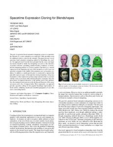
Fig. 2. Performance comparisons
� ��
In Figure 2 (a), we set � . We use the sphere-decoding (SD) algorithm for the LCF-STC [12] designs, while for ST-OD, we use ML exhaustive search for each symbol. For our FDFRLCF-STC, we use SD and the nulling-cancelling (NC) scheme of Section 3.2. It can be seen that the performance of our FDFR design with SD is quite close to that of ST-OD. When � increases to as shown in Figure 2 (b), the gap between FDFR and STOD widens. This is because ST-OD losses information rate when (see [7] for details). To reduce the decoding complexity of � our FDFR design, we use sub-optimal decoding (NC) which sacrifices performance (diversity) to lower the decoding complexity. (Figure 2 (a)), the performance with NC is worse When � than ST-OD and FDFR with SD. However, when � increases to , FDFR with NC outperforms ST-OD and LCF-STC over a large SNR range.
This proposition shows that without sacrificing performance, it is possible to reduce decoding complexity, by reducing transmission rate. An alternative way to reduce complexity is to use sub-optimal decoding (e.g., nulling-cancelling). In this case, we know that the performance will be compromised. Define the QR-decomposition of the channel matrix � as
�� �� � � �� � � � �
� �
�
� � ��
� ��
Figure 3 compares the performance of our FDFR scheme against LCF-STC [12], when . BPSK is used for the � � FDFR scheme, and -QAM is for the LCF-STC in [12]. The LCF � ��� . From Figure encoder � is selected as in (11) and 3, we observe that our FDFR scheme achieves the same diversity as LCF-STC, but has better performance because it can afford a smaller modulation for the same transmission rate.
�
�� � � � � ��� �� ���
�
�
� �
� ��� � �
It has been shown in [3] that
� � � �� � ���� � �� !� � �
� � �� �� � ���� � � ��� � �� � denotes the chi-square distribution with � degrees of free� �
�
�
�� � � � � �� �� � � � � �� .
. . . .. ��� �
� �
�
�
where � dom. To quantify the price paid in performance with the nullingcancelling decoder outlined in Section 3.2, we need the following proposition (its proof is similar to that in [11], and is omitted here due the lack of space): Proposition 3 Using nulling and cancelling as proposed in Section 3.2, the design in (4) achieves diversity of order � � � for the th decoded layer, when there is no error propagation.
��
445
�
� �� �
When error propagation is accounted for, the system performance is dominated by the worst layer, and the system diversity order be, that of the worst layer’s diversity. comes � � �
� �� � ��
When the transmission rate is fixed, we can sacrifice diversity to lower the decoding complexity. The interesting case is when we can compromise the rate, to make up for some diversity order. In the following, we will elaborate further on these performance-rate tradeoffs. Suppose one of the layers in (4) is zero. Using Proposition 3, we can then verify that the system diversity order becomes , which is greater than that of (4). However, � � � symbols pcu. How the transmission rate now becomes � to optimize this performance-rate tradeoff is an interesting open problem. Subsequently, we will use an example to illustrate this tradeoff, based on two important parameters. One is the channel’s coherence time , and the other is the layer size, which also controls the decoding complexity. A clarification is due at this point: when we talk about the performance-rate tradeoff, we need to maintain comparable decoding complexity, by fixing the length of each layer. For a fixed channel coherence time , we obtain a family of performance-rate tradeoff curves by varying .
� �� � ��
� �
�
�
� �� ��
�
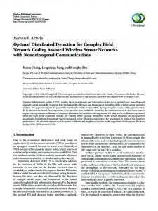
. The channel matrix � has Example: Select � � i.i.d. complex Gaussian entries. The length of each layer is . The LCF-STC encoder design (see [6, 12], or Section 3) is used for each layer so that Proposition 3 holds true. We use the layer as a unit to adjust the rate, i.e., if we want to reduce rate, we remove layers instead of individual symbols. When the channel coherence time is � , we can directly obtain diversity order , where � � � . When � , we have more flexibility in this trade, where off since the rate is � . When � , full diversity � � cannot be achieved per layer. We . then select the layer length equal to �
�
� �� � � � �� � �� � � �� � � ��� � � �� � � � � �� �� � �� �
�� � � � � � � "�
��
16 14 d
diversity order G
10
2 1
5. REFERENCES [1] S. M. Alamouti, “A simple transmit diversity technique for wireless communications,” IEEE JSAC, vol. 16, no. 8, pp. 1451–1458, Oct. 1998. [2] M.O. Damen, A. Tewfik, and J.-C. Belflore, “A construction of a space-time code based on number theory,” IEEE Trans. on Infor. Theory, vol. 48, pp. 753–760, March 2002. [3] G. J. Foschini, “Layered space-time architecture for wireless communication in fading environments when using multiple antennas,” Bell Labs. Tech. Journal, vol. 2, Autumn 1996. [4] G. J. Foschini and M. J. Gans, “On limits of wireless communication in a fading environment when using multiple antennas,” Wireless Personal Communications, vol. 6, no.3, pp. 311–335, Mar. 1998. [5] H. E. Gamal and A. R. Hammons Jr., “A new approach to layered space-time coding and signal processing,” IEEE Trans. on Infor. Theory, vol. 47, pp. 2321 -2334, Sept. 2001. [6] X. Giraud, E. Boutillon, J. C. Belfiore, “Algebraic tools to build modulation schemes for fading channels,” IEEE Trans. on Infor. Theory, vol. 43, no. 3, pp. 938–952, May 1997. [7] X. Ma, and G. B. Giannakis, “Complex field coded MIMO systems: performance, rate, and tradeoffs,” Wireless Communications and Mobile Computing, submitted June 2002. [8] V. Tarokh, N. Seshadri, and A. R. Calderbank, “Space-time codes for high data rate wireless communication: performance criterion and code construction,” IEEE Trans. on Infor. Theory, pp. 744–765, Mar. 1998.
[10] P. W. Wolniansky, G. J. Foschini, G. D. Golden, and R. A. Vlenzuela, “V-BLAST: An architecture for realizing very high data rates over the rich-scattering wireless channel,” Proc. of URSI International Symposium Signals, Systems, and Electronics, Italy, Sept. 1998.
T
8
4
���
[9] V. Tarokh, A. Naguib, N. Seshadri, and A. R. Calderbank, “Combined array processing and space-time coding,” IEEE Trans. on Infor. Theory, vol. 45, pp. 1121–1128, May 1999.
12
6
ent from the diversity versus rate figure in [13]. The rate in [13] is defined as the limit of transmission rate divided by � (SNR) when the SNR goes to infinity; while in our approach, we define transmission rate as the number of symbols pcu. Therefore, if we fix the constellation for any SNR, all curves in Figure 4 will show up as points at rate zero in the figure of [13].
ML decoding (T>N ) t ML decoding (T=Nt−1) NC (T=Nt) NC (T=2Nt) NC (T=4Nt) NC (T=Nt−1) 1.5
2 2.5 3 symbol rate R (symbols pcu)
3.5
4
Fig. 4. Diversity versus rate tradeoffs From Figure 4, we observe that: i) as increases, we have more flexibility to trade-off rate with performance; ii) as increases, diversity with nulling-cancelling (NC) suboptimal decoding comes closer to the optimal decoding; and iii) to achieve full diversity, we need �. Note that here our diversity versus symbol rate figure is differ-
� �
� �
[11] Y. Xin, Z. Liu, and G. B. Giannakis, “High-rate layered space-time coding based on linear constellation precoding,” Proc. of Wireless Communications and Networking Conf., vol. 1, pp. 471–476, Orlando, FL, March 17-21, 2002. [12] Y. Xin, Z. Wang, and G. B. Giannakis, “Space-time diversity systems based on linear constellation precoding,” IEEE Trans. on Wireless Communications, 2002 (to appear); see also Proc. of GLOBECOM, vol. 1, pp. 455-459, San Antonio, TX, Nov. 25–27, 2001. [13] L. Zheng and D. Tse, “Optimal diversity-multiplexing tradeoff in multi-antenna channels,” Proc. of the 39th Allerton Conference on Communication, Control and Computing, pp. 835–844, Monticello, IL, Oct. 2001.
446