Journal of Physics: Conference Series
PAPER • OPEN ACCESS
Leakage flow reduction in different configuration of labyrinth seal on a turbine blade tip To cite this article: Piotr Kaczyski et al 2018 J. Phys.: Conf. Ser. 1101 012012
View the article online for updates and enhancements.
This content was downloaded from IP address 181.214.209.235 on 24/10/2018 at 02:23
XXIII Fluid Mechanics Conference (KKMP 2018) IOP Conf. Series: Journal of Physics: Conf. Series 1101 (2018) 1234567890 ‘’“” 012012
IOP Publishing doi:10.1088/1742-6596/1101/1/012012
Leakage flow reduction in different configuration of labyrinth seal on a turbine blade tip Piotr Kaczyński, Ryszard Szwaba, Filip Wasilczuk, Paweł Flaszyński, Piotr Doerffer Institute of Fluid-Flow Machinery, Polish Academy of Sciences E-mail:
[email protected] Abstract. This paper contains experimental and numerical investigation of the leakage flow over the blade tip in turbine stage. Experiments were conducted in non-rotating linear channel. Test rig was intended to model the geometry of the labyrinth seal of the blades of the lower pressure turbine stage. Investigated model contained two different geometries of labyrinth fins. Moreover smooth and honeycomb stator landing were tested. Experimental measurements have been supported by CFD simulation which gives valuable information of flow structure in labyrinth seal and show complex flow physics in the investigated model.
1. Introduction Aircraft engine manufacturers are continuously working on reducing the overall engine weight and efficiency increase which result in reduction of specific fuel consumption. One of the way to reach these goals is to decrease a losses generated in turbine stage. The sources of those losses can be divided into three main category: profile losses, end-wall losses and leakage losses [1]. The great importance for overall performance of turbine stage have a losses generated between turbine casting and the tip of a blade. Leakage flow in sealing region can reach up to one of third of total losses in turbine cascade [2]. The shrouded blades with labyrinth seal equipped with fins are a commonplace in turbomachinery [3]. It is intended to reduce leakage flow by dissipating the kinetic energy of fluid which flows through the clearance or to increase the flow resistance by modifying a sealing geometry. The most used types of labyrinth seals are the straight, interlocking, slanted, stepped ones and their combinations [4]. On one hand it is desire to keep clearance as small as possible to avoid additional losses. However the different operating conditions of turbine stage significant influences on thermal and mechanical displacement of stationary and rotating parts of the sealing. Therefore the operational gap size changes during the work and it can influence on leakage mass flow rate. In order to minimalize tip clearance the wear-in materials in stationary landing are used. An example of abradable coating is a honeycomb structured material. Such a solution allows to transient contact between labyrinth fins and landing. Moreover that type of seal provides to reduce the operating tip clearance [5]. Despite of benefits of honeycomb land, it enlarges effective gap size and increases leakage flow rate compare to the same configuration with smooth wall [6]. The paper contains the experimental investigations and numerical calculation which have been conducted in non-rotating linear channel. The test rig is intended to model the geometry of the labyrinth seal of the blades of the lower pressure turbine stage. Labyrinth seal was equipped with two angled fins which can be replaced by the other fins geometry. The stator land has two configurations, first with smooth wall while the second is material with honeycomb structure. Additionally, four different gap Content from this work may be used under the terms of the Creative Commons Attribution 3.0 licence. Any further distribution of this work must maintain attribution to the author(s) and the title of the work, journal citation and DOI. Published under licence by IOP Publishing Ltd 1
XXIII Fluid Mechanics Conference (KKMP 2018) IOP Conf. Series: Journal of Physics: Conf. Series 1101 (2018) 1234567890 ‘’“” 012012
IOP Publishing doi:10.1088/1742-6596/1101/1/012012
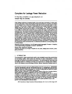
size have been tested in the range from 0.6 mm up to 1.2 mm. The geometry used in numerical calculation corresponds to experimental one. The computational structured mesh has around 6 million cells. The solver which have been used in numerical calculation is Ansys/Fluent with k-w SST turbulence model. The research focuses on impact of the clearance size and labyrinth seal configuration on leakage flow. Experimental measurements have been supported by CFD simulation which gives valuable information of flow structure in labyrinth seal and show complex flow physics in the investigated model. 2. Test stand The real view of the measurement test stand is shown in figure 1. Downstream of the inlet (on the left) a laminar mass flow meter with automatic control valve is located. The test stand outlet is connected to the vacuum tank throughout the control valve, so the air flows through the measurement section driven by the pressure difference between the ambient and very low pressure in the vacuum tank. Measurement section contains a model of two fins labyrinth sealing and appropriate scaled to its size the narrow inlet and outlet channel. The test stand has a possibility to control the inlet and outlet pressure independently. By means of two valves (at inlet and outlet) the mass flow and adequate pressure drop in the test section is controlled.
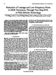
Figure 1. View of the test stand. The schematic view of the measurement section is shown in figure 2. The main part of this section is the bottom insert with two fins which are 10 mm high and it can be replaced by the other type of fins. In reference case the width of fin tip is 0.8 mm. Modified fins are thickened and their width of tip has 2.6 mm. Just above the fins removable top insert is located. In reference configuration it is flat (smooth) wall and it can be replaced by honeycomb landing. The clearance between the fins and top landing is adjustable by means of four control micro screws (see figure 1) which are working independently allowing to set even clearance above two fins and also parallel in spanwise direction. Size of inlet and outlet channel is 11 mm for the gap of 1 mm and changing with the different clearance size. Measurement section was equipped with the Prandtl Probe and thermocouple located 135 mm upstream of the main measurement channel and 200 mm upstream of the finned bottom insert. Moreover 11 pressure taps were located at the bottom wall and bottom insert (red vertical lines in figure 2). The inlet total pressure was set at 48 kPa
2
XXIII Fluid Mechanics Conference (KKMP 2018) IOP Conf. Series: Journal of Physics: Conf. Series 1101 (2018) 1234567890 ‘’“” 012012
IOP Publishing doi:10.1088/1742-6596/1101/1/012012
Figure 2. Scheme of the measurement section.
3. Numerical model Inlet conditions as a stagnation pressure was set on 48 kPa, the same as in experimental measurements. Other boundary conditions at the inlet were agreed as follows: temperature on 297 K, turbulent viscosity ratio on 4.5 and turbulence intensity on 0.5%. As outlet boundary condition the static pressure was used, with range from 25 to 46 kPa. Moreover, boundary condition for the walls in numerical model are nonslip and adiabatic. Inlet cavern and labyrinth seal region were connected using non-matching interface. It was used in order to decrease number of cells of the model. Both sides of non-matching connection in the boundary layer mesh was kept identical to eliminate any distortion in these areas. In configuration with flat landing the grid reached almost 6 million of cells and the whole channel width (figure 3, top) was simulated. In case of honeycomb landing (figure 3 bottom) the width of the model was limited to the approximately 5 mm in order to reduce amount of cells which was 6.4 million. Mesh in honeycomb region was prepared as an unstructured grid and connected with main model by non-matching connection technique. The other parameters set in numerical calculations are presented in Tab. 1.
Figure 3. Boundary conditions for the numerical calculations.
3
XXIII Fluid Mechanics Conference (KKMP 2018) IOP Conf. Series: Journal of Physics: Conf. Series 1101 (2018) 1234567890 ‘’“” 012012
IOP Publishing doi:10.1088/1742-6596/1101/1/012012
Table 1. Numerical features Solver Type of grid Physical model Turbulence model Gas model Numerical scheme Spatial discretization Viscosity
Ansys Fluent, Finite volume, pressure based Structured and Unstructured Reynolds-average Navier-Stokes (RANS) k- SST Perfect gas SIMPLE Upwind scheme – 2nd order According to Sutherland’s law
4. Flow parameter determination In order to compare data from different configuration the dimensionless approach was applied. Operational pressure ratio and discharge coefficient CD were used. The pressure ratio is calculated dividing inlet total pressure (p0,in) by the static pressure (ps,out) measured at the outlet of the measurement section. Inlet total pressure was taken from Prandl Probe. Static pressure at the outlet was measured by means tap located 10 mm downstream of the second fin (pressure tap number 11). In case of numerical calculation ps,out was calculated using average pressure at the plane corresponding to pressure tap (Control plane, see figure 3). It is defined by the following relation ,
=
(1)
,
The mass flow rate parameter is often insufficient to comprehensively compare and evaluate leakage reduction in different labyrinth seal configuration. It depends from many factors such as geometry of the sealing or the total inlet parameters, which are variable in time due to the characteristic of the installation. Therefore frequently met in the literature dimensionless flow coefficients is used [7]. Discharge coefficient allows to compare the level of leakage flow through the different sealing shapes and sizes including varying values of fluid parameters. The CD coefficient is defined as a ratio of the mass flow rate through the model of the seal to that of an isentropic nozzle with the same surface area. =
̇
(2)
̇
The mass flow rate under the perfect fluid condition is defined as:
̇
=
, ,
2 ( − 1)
1
−
1
(3)
where: p0,in is inlet total pressure, T0,in – inlet total temperature, A – clearance area in spanwise direction, R – individual gas constant, κ – isentropic exponent, – operational pressure ratio. 5. Results The figures from 4 to 6 have the same pattern and consists of two charts. On the left hand side discharge coefficient in function of operational pressure ratio is presented while on the right hand side mass flow rate for different operating pressures is drawn. Figures contains different fins and landing configuration and also four level of gap sizes (0.6 mm, 0.75 mm, 1 mm and 1.2 mm). Red line represents reference thin fin geometry (REF, 0.8 mm) and black line thickened fin (TF, 2.6 mm) one, for flat landing (FW, figure 4) and honeycomb landing (HC, figure 5) with gap size 0.6 mm. Results for tip clearance of 0.75
4
XXIII Fluid Mechanics Conference (KKMP 2018) IOP Conf. Series: Journal of Physics: Conf. Series 1101 (2018) 1234567890 ‘’“” 012012
IOP Publishing doi:10.1088/1742-6596/1101/1/012012
mm are shown by blue (thin fin) and green (thickened fin) colour lines on the same figures. Chart in figure 6 is drawn in the same pattern as previous while it is dedicated for gap size 1 mm and 1.2 mm. Figure 4 shows the comparison of reference and thickened fins for flat landing and tip clearance of 0.6 and 0.75 mm. In this figure one can observes that thickened fins (tip width of 2.6 mm) contribute to the increase in mass flow rate regarding to reference type (tip width of 0.8 mm) in case of flat landing. The distinction between reference and thickened fins increases as the gap size is growing. There is no noticeable discrepancies in result between the discharge coefficient and mass flow rate values in terms of leakage reduction.
Figure 4. CD coefficient and mass flow rate for reference and thickened fins with smooth land, gap size: 0.6 mm and 0.75 mm. In the contrary to the flat type of landing, the thickened fins in the honeycomb configuration (figure 5) reduces the leakage flow in relation to the thinner fins. The largest differences are observed for gap size of 0.6 mm. As the clearance size increases the differences in mass flow between reference and thickened fins gradually vanishes (figure 6). In case of the highest gap size (1.2 mm) leakage flow rate for both type of fins is almost similar.
Figure 5. CD coefficient and mass flow rate for reference and thickened fins with honeycomb land, gap size: 0.6 mm and 0.75 mm. The higher mass flow rate through labyrinth seal in configuration with thickened type of fins with flat landing can be explained by the numerical simulation and it results from different flow pattern in the gap region. The flow above the reference fins (tip width of 0.8 mm) starts to separate at the leading edge (figure 7) and the reattachment on such short distance is not observed. It results in decrease of effective gap size and thereby reduces the leakage flow. For the thickened fins (tip width of 2.6 mm) a slightly different flow structure in the gap region is observed. Initially the flow separation at the leading edge of fin also appears, afterwards one can observe the reattachment of the flow (figure 8). It results in increasing of effective gap size and higher mass flow rate.
5
XXIII Fluid Mechanics Conference (KKMP 2018) IOP Conf. Series: Journal of Physics: Conf. Series 1101 (2018) 1234567890 ‘’“” 012012
IOP Publishing doi:10.1088/1742-6596/1101/1/012012
Figure 6. CD coefficient and mass flow rate for reference and thickened fins with honeycomb land, gap: 1.0 mm and 1.2 mm.
Figure 7. Velocity contour for reference fins with smooth land.
Figure 8. Velocity contour for thickened fins with smooth land. The presence of the honeycomb landing in the labyrinth sealing considerably modifies the flow structure in the tip clearance region. As it is shown on velocity contours in the figure 9 and 10, part of the flow can use additional available space in honeycomb cells above fins. It happens especially in case of reference thin fins (figure 9) where the leakage flow tries to omit the fin by the space of honeycomb cell and in consequence the effective gap size increases. Thickened fins which covers higher area of honeycomb cell are the larger obstacle and such geometry puts forward a higher resistance to the flow. It results in reduction of effective clearance size in relation to the thinner fins and finally the mass flow rate decreases. As the gap size is increasing, honeycomb cells have less influence on leakage flow and the differences in the mass flow rate between reference and thicken fins gradually diminishes.
Figure 9. Velocity contour for reference fins with honeycomb land.
6
XXIII Fluid Mechanics Conference (KKMP 2018) IOP Conf. Series: Journal of Physics: Conf. Series 1101 (2018) 1234567890 ‘’“” 012012
IOP Publishing doi:10.1088/1742-6596/1101/1/012012
Figure 10. Velocity contour for thickened fins with honeycomb land. The plot in figure 11 shows an example of normalized static pressure distribution along the measurement section. The stagnation pressure p0,in was equal to 48 kPa and pressure ratio π = 1.25. The coordinates X in range of 96.5mm to 103.5mm are located between the fins. Red and black line represents the flat landing with reference (tip width of 0.8 mm) and thickened fins (tip width of 2.6 mm), respectively. Blue line shows the distribution for honeycomb landing configuration with the reference fins and the green colour line represents the thickened fins. It is worth to noticed, that the pressure distribution on the lower wall varies depend on which sealing configuration is applied. In the figure 11 one can notice constant pressure and velocity region at the channel inlet of the measurement section. Next there is a large pressure drop over first fin, between the fins the pressure is more or less constant and finally downstream of the second fin a further pressure drop is observed. The pressure at the outlet slightly increases (velocity decreases) as a stabilisation process downstream of the vortex pattern created behind the labyrinth seal.
Figure 11. Normalized pressure distribution on bottom wall of measurement section. The range of pressure jump on particular fins is different depend on configuration of labyrinth seal. As the total pressure drop is the same for all flow cases it can be observed that large pressure drop on the first fin is accompanied with small one on the second fin. It means that depends on sealing geometry, the loading of first and second fin is different. The higher difference one can notice especially in case of thinner reference fins for flat and honeycomb landing. It is due to various inflow angle upstream of the second fin resulting from different flow pattern between the fins in these flow cases, see figure 7 and 9. The stream deflection downstream of the first fin is totally different in case of honeycomb landing (figure 9). For thicker fins the difference in flow pattern is not so much visible, therefore the pressure drops on particular fins in case of flat and honeycomb landing are more approached.
7
XXIII Fluid Mechanics Conference (KKMP 2018) IOP Conf. Series: Journal of Physics: Conf. Series 1101 (2018) 1234567890 ‘’“” 012012
IOP Publishing doi:10.1088/1742-6596/1101/1/012012
6. Conclusions An experimental investigations has been performed to investigate the possibilities of the mass flow reduction in the blades labyrinth seal. During the research there was tested geometries which comprised modified labyrinth seal with different landings (flat and honeycomb). The seal geometries of thickened fins, besides the valuable results showing its work in different sealing configurations, is basis for future investigation of passive flow control (air curtain) solution performance in the shrouded blades. The results of this leakage reduction method was compared against the reference geometry (fins, 0.8 mm thick) in terms of seal aerodynamic performance. Reynolds number based on the fin height was varied between 1500 and 9500 depend on flow condition, meanwhile for such Re the flow velocity in the channel inlet was changing from U=2.7 to 15.5 m/s. The following conclusions can be drawn from the carried out experimental investigations: The pressure drop in the channel on particular fins depends on configuration of labyrinth seal. The larger pressure drop on the first fin is accompanied with smaller one on the second fin, which means that the loading of first and second fin is different. The higher difference is observed in case of comparison of thinner reference geometry in flat and honeycomb landing. It is due to various inflow angle upstream of the second fin. For thicker fins the difference in flow pattern between both type of landings is not so noticeable, therefore the pressure drops on particular fins are more approached. In the channel with flat landing, the fins thickening causes the mass flow increase in the sealing in relation to the reference flow (thinner fins) in the range of 5÷20%. The different flow behaviour is observed in the channel with honeycomb landing. The mass flow reduction (up to 25%) for geometry with thicken fins is observed, but the tendency towards leakage reducing with the growing gap size is decreasing. There is the other possible solution to reduce the leakage in sealing with honeycomb, i.e. by decreasing the honeycomb cell size, what in turbine applications can be easier than the thickening of sealing fins. However this proposal should be verified in further research. References [1] Denton J D 1993 Loss mechanisms in turbomachines J. Turbomach. 115 621-656 [2] Hamik M and Willinger R 2008 An innovative passive tip leakage control method for axial turbines: linear cascade wind tunnel results ASME Turbo Expo 2008: Power for Land, Sea, and Air (Berlin) vol 6 927-938 [3] Ghaffari P, Willinger R, Bauinger S and Marn A 2015 Impact of passive tip-injection on tipleakage flow in axial low pressure tubine stage ASME Turbo Expo 2015: Turbine Technical Conf. and Exposition (Montreal) vol 2A V02AT38A002. [4] Chupp R E, Hendricks R C, Lattime S B and Strinetz B M 2006 Sealing in turbomachinery J. Propulsion and Power 22 313-349 [5] Burcham R E and Keller R B Jr 1978 Liquid rocket engine turbopump rotating-shaft seals NASA SP-8121 [6] Schramm V, Willenborg K, Kim S and Wittig S 2000 Influence of a honeycomb facing on the flow through a stepped labyrinth seal ASME J. Eng. Gas Turbines Power 124 140-146 [7] Braun E, Dullenkopf K and Bauer H J 2012 Optimization of labyrinth seal performance combining experimental, numerical and data mining methods ASME Turbo Expo 2012: Turbine Technical Conf. and Exposition (Copenhagen) vol 4 1847-54
8