Vision server: A special vision hardware is connected to a host workstation via a VME ... dedicated to recognition of actions, plan analysis, and plan instantiation.
IEEE TRANSACTIONS ON ROBOTICS AND AUTOMATION, VOL. XX, NO. Y, MONTH 1994
1
Learning by Watching: Extracting Reusable Task Knowledge from Visual Observation of Human Performance Yasuo Kuniyoshi, Masayuki Inaba, and Hirochika Inoue, Member, IEEE
Abstract | A novel task instruction method for future intelligent robots is presented. In our method, a robot learns reusable task plans by watching a human perform assembly tasks. Functional units and working algorithms for visual recognition and analysis of human action sequences are presented. The overall system is model based and integrated at the symbolic level. Temporal segmentation of a continuous task performance into meaningful units and identi cation of each operation is processed in real time by concurrent recognition processes under active attention control. Dependency among assembly operations in the recognized action sequence is analyzed, which results in a hierarchical task plan describing the higher level structure of the task. In another workspace with a di�erent initial state, the system re-instantiates and executes the task plan to accomplish an equivalent goal. The e�ectiveness of our method is supported by experimental results with block assembly tasks. Keywords| Learning Robot, Computer Vision, Action Recognition, Symbolic Plan Analysis, Real Time Processing
F
I. Introduction
UTURE intelligent robots are expected to work with humans in unstructured environments. In such situations, a wide variety of task instructions will be given to the robots under following conditions: 1. The end-users have working knowledge of the target tasks but are novice at programming or operating robots. 2. Well-equipped programming facilities or expert robot programmers may not be accessible. 3. The time and the e�ort required for task instruction is strictly limited. 4. The environment is uncontrollable. Special xtures or feeders are not available. 5. The end result of the instruction should be highly reusable. 6. The end-users must not be exposed to any danger. Unfortunately, existing methods of robot programming are not directly applicable to the above situation. This paper presents a framework, a design, and implementation of a novel functionality for future intelligent robots called \learning by watching". With this functionality, the robots will intelligently acquire reusable task knowledge quickly
Y. Kuniyoshi is with the Autonomous Systems Section, Intelligent Systems Division, Electrotechnical Laboratory (ETL), 1-1-4 Umezono, Tsukuba, Ibaraki, 305 Japan. M. Inaba and H. Inoue are with the Department of MechanoInformatics, the University of Tokyo, 7-3-1 Hongo, Bunkyo-ku, Tokyo, 113 Japan.
and safely by watching without disturbance human workers perform tasks.
A. Existing Methods for Task Instruction Until now, basically four approaches to robot programming have been pursued: teaching by guiding, text programming, o�-line simulation-based programming, and inductive learning. Although text programming is suitable for sophisticated applications, it requires special skills and much e�ort to write complete robot programs. This problem motivated the development of task level robot languages [1], [2], [3]. But it turned out that application of a general purpose task planner to practical domains results in an explosion in the number of declarations and computational time. O�-line simulation-based programming [4], [5], [6] techniques integrate direct teaching in a simulated world, text programming, and model-based motion planners on a common platform. These techniques are quite powerful, but it requires expensive special-purpose hardware such as a highresolution graphics display and a 3D pointer. Moreover, a user must supply a complete description of the real world to the system. This is a costly procedure. With inductive learning, a robot can learn appropriate motion and sensing strategies through trial and error [7]. This imposes the least burden on the user, but it is not adequate for instructing complex task structures to robots. Rather, this method is useful for adding re nements to other methods. \Teaching by guiding" is a straightforward method in which a human instructor achieves the desired task by operating a robot manipulator in the real world while its motion is recorded. This has been the most widely practiced retraining method for industrial robots for the following reasons: it requires no additional hardware, no expertise in computer programming, no extra e�ort such as close analysis of the task and no complete description of the workspace structure. Despite its tness to eld robot programming, teaching by guiding su�ers from serious drawbacks concerning exibility, robustness, sensor utilization and safety. It forces the user to accomplish the task using real manipulators, which is exhausting, often leads to wrong moves and can sometimes be risky. The result is very hard to modify or debug, and is not transferable to di�erent manipulators or workspace states. Furthermore, the method cannot handle sophisticated sensor interactions.
2
IEEE TRANSACTIONS ON ROBOTICS AND AUTOMATION, VOL. XX, NO. Y, MONTH 1994
Several e�orts have been made to cope with these problems by improving or extending the method. This is done by gathering sensory information during task instruction and embedding sensor utilization codes into template programs by interacting with the user [8], extracting dynamic control rules for a particular assembly motion from the position and force data of human performance [9], integrating task level languages and direct teaching through masterslave manipulators [10]. Despite these e�orts, achieving robustness and exibility while maximizing the merits of teaching by guiding is still an open problem.
B. Teaching by Showing The original concept of teaching by guiding has several noteworthy features: 1. Direct: The instructor directly performs the target task while watching the actual workspace. This is intuitive and does not spoil the working knowledge about the task. 2. Tacit: No explicit statements about the target task or the workspace need to be made. 3. Inexpensive: No extra hardware is required. There is room for improvement for item 1, this is because operating a real manipulator to achieve a task imposes an extra burden on the instructor. If we can solve this problem and retain items 2 and 3, an ideal framework of task instruction for the next generation robots will be near at hand. Obviously, the most natural form of task performance by a human instructor is to perform the task in the usual manner, e.g. using his/her own hands. The robot should extract knowledge from the task's performance without disturbing it. A passive remote sensor, vision, is the best device for this purpose. It is envisaged that vision will be part of the standard equipment in future intelligent robots. Visual recognition of human actions is becoming feasible due to recent development in vision algorithms and processors. Moreover, optimal values of motion parameters such as trajectory and velocity of the manipulator depend on the con guration of the workspace and the structure of the manipulator. In contrast, task plans described in terms of more abstract and qualitative representation of assembly operations such as pick and place are of high reusability. We have proposed a novel framework of task instruction called \teaching by showing" [11]. It consists of ve phases: Presentation: The instructor shows the target task to the system by performing it with his hands. The instructor needs to perform the task only once from start to end without pausing. Recognition: The system observes the performance by vision and constructs a symbolic description of the task. Recognition must be completely automatic and in real time in order to keep up with the performance of the task by the instructor. Analysis: The system analyzes the task description and extracts higher structures such as a goal hierarchy and dependency among operations.
Generation: For a given target workspace, the system
recognizes the initial con guration of the objects, modi es and instantiates the task description, and generates an executable robot program. Execution: The program is executed to accomplish the task with a manipulator. Our method is direct, tacit, and inexpensive. Also, the method is quick and safe due to single continuous presentation in a nearby workspace with undisturbing observation by the robot. The method is exible because the task is described symbolically, allowing re-instantiation and modi cation in various situations.
C. Learning by Watching Realization of visual recognition and interpretation of human action sequences is of critical importance to the development of teaching by showing. Early attempts at this problem were made on simple gures moving around in two-dimensional world [12], [13], [14]. A progress concerning teaching data has been made: A learning system was built which extracts complex task structures from manipulator command sequences issued by a human operator [15]. And a telerobotic system which recognizes pick and place sequences from force/joint data was developed [16]. Recently, several attempts have been made which conform to the \teaching by showing" framework: An \assembly plan from observation" system [17] extracted ne motion sequences from transitions among face contact states acquired by a range sensor. And integration of a symbolic recognizer and a playback module using visual servo was attempted for two dimensional pick and place operations [18]. However, none of these systems dealt with real time visual recognition of continuous human action sequences in the three dimensional world. Classical recognition techniques must be reconsidered under real time constraints. Runtime temporal segmentation of the task into meaningful units becomes crucial when a continuous ow of actions is given. Moreover, integration with higher level processing such as task planning or generalization needs to be considered. II. System Design
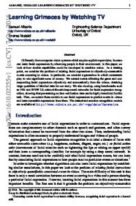
An overview of the system [19], [20] is shown in Fig. 1. The overall structure re ects the framework of \teaching by showing" presented in section I-B.
A. Required Functions Learning by watching consists of three major functions which must be integrated as a unity: seeing, understanding and doing. Our approach is to connect these at the symbolic level. From this viewpoint, each function can be speci ed as follows: 1 1 This paper put emphasis on \seeing" and \understanding".
KUNIYOSHI, INABA AND INOUE: LEARNING BY WATCHING Seeing
Doing
Cameras L
Human Instructor
Cartesian Arm
Cameras L
Z R R
6DOF Wrist Gripper
MWVS (R) Cam. SEL MWVS (L) LSF
R L
Wrist/Gripper Controller
Monitors
VME BUS
RS232
SCSI
SUN3/50
Visual Recognition
SUN4/110
Arm Controller
Motion Server
Vision Server
Understanding SUN4/60
Action Recognition Plan Analysis
Motion Generation Plan Instantiation
ethernet
SUN3/80
Fig. 1. Overview and hardware con guration of the system.
Seeing: (1)Recognizing the initial state and construct
the environment model. (2)Finding and tracking the hand. (3)Visual search for the target of operation. (4)Detecting meaningful changes around the target and describe them qualitatively. Understanding: (1)Segmentation of the continuous task performance into meaningful unit operations. (2)Classi cation of operations based on motion types, target objects, and e�ects on the targets. (3)Dependency analysis of a task procedure to extract subprocedures consisting of mutually dependent operations. (4)Bottom-up plan inference. Generate higher-level operators for each subprocedure and gather target objects and state change descriptions from the lower-level operators. Doing: (1)Instantiation of the task plan. Recognize the given initial state. Match the result with the stored task plan to produce goal positions for each operation. (2)Path planning and generation of motion commands. (3)Sensor feedback for guiding motions. (4)Error detection by the vision and recovery actions. 2
B. Experimental Setup The hardware setup of the system is shown in Fig. 1. The system consists of three parts (divided by dotted lines in the gure) for seeing, understanding and doing. Camera con guration: Task presentation is monitored by three monochrome video cameras (two for stereo and one for zoom-in) connected to a network-based robot vision server [21]. Another stereo pair of cameras are used for monitoring task execution. 2 The function of \doing" will be discussed only brie y. Items 3, 4 in \doing"are not yet implemented.
3 In our experiments, each stereo pair of cameras was con gured as the baseline being about 240 mm, and the distance to the worktable being about one meter. External parameters of each camera were calibrated by taking a line image of a precisely shaped block placed at the origin of the world coordinates and matching it with the geometric model using Lowe's method [22]. Vision server: A special vision hardware is connected to a host workstation via a VME bus. The host runs a server process which accepts commands, controls the vision hardware and transmits the extracted data via a socket connection over an Ethernet network. The vision hardware consists of a high speed Line Segment Finder (LSF)[23] and a Multi Window Vision System (MWVS)[24]. The LSF extracts lists of connected line segments from a gray scale image (256 2 256 pixels) within 200 msec. The MWVS hardware is multi processor. It extracts various image features at video rate from within rectangular \windows" of speci ed size, sampling rate and location. It can handle up to 32 windows in parallel for continuous tracking and detection of features. High-level processing servers: Two workstations are dedicated to recognition of actions, plan analysis, and plan instantiation. The action recognizer consists of an action model, an environment model and an attention stack. It extracts visual features by actively controlling the vision server and generates a symbolic description of the action sequence in near real time. The plan analyzer extracts high level task structures from the action sequence. The acquired plan is matched against the environment model which is re-initialized by visual recognition of the execution environment. Then, motion commands for the manipulator are generated and sent to the motion server. The programs are written in an object-oriented style using EUSLISP, an object-oriented Lisp environment with geometric modeling facilities [25]. Motion server: A cartesian type arm with a 6 DOF parallel-link wrist mechanism [26] supporting a parallel-jaw gripper is used for task execution. This manipulator is controlled by a dedicated CPU board (for the wrist) and a PC (for the arm) running servo and command interpreters. The host workstation interprets robot commands from the Ethernet network, performs the necessary coordinate transformations and sends primitive instructions to the manipulator controller. III. Active Vision for Observing Actions
Restricting the amount of visual information while retaining the important portions is the key to real time recognition of human action sequences. There are two axes for a restriction scheme: (1) Use of regions of interest (windows). (2) Selecting speci c features to extract. Both should be actively controlled [27] with regard to the task context.
A. Visual Feature Detectors
4
IEEE TRANSACTIONS ON ROBOTICS AND AUTOMATION, VOL. XX, NO. Y, MONTH 1994 left camera model
VFD MFD (left)
ENV-node
SFD (stereo)
right camera model
MFD (right)
vision resource manager
: control, inquiry, request : data, resource Fig. 2. Vision Processing Elements. ENV-node: ENVironment model node. VFD: Visual Feature Detector. SFD: Stereo Feature Detector. MFD: Monocular Feature Detector. The camera models and the vision resource manager are shared by all VFDs. The arrows are realized as sending messages (black) and return values (gray).
The vision processing consists of the modules shown in Fig. 2. They are implemented as EUSLISP objects. A Visual Feature Detector (henceforth, VFD) represents a unit of vision processing as a combination of visual attention and a feature extraction algorithm. As long as the hardware resource allows, any number of VFDs can be created and used in parallel during recognition. Five types of VFDs are used in our system; motion-detector, object nder, sil- nder, change-detector, and coplanar-detector. The algorithms are described in the following subsections. An ENVironment model node (ENV-node) is an element of the environment model (see Section IV-A) which sends requests to a VFD and receives detected features. The left/right camera models maintain calibrated camera models and computes forward/backward projection, such as a view-line from a screen point . The vision resource manager maintains the vision hardware resource (the windows and the processors in the MWVS). On request from the MFDs, it allocates/initializes/frees a speci ed amount of windows/processors and returns a control handle. A VFD is programmed as a Stereo Feature Detector (SFD) class and a Monocular Feature Detector (MFD) class. When an ENV-node needs a VFD, it instantiates one SFD. The SFD then instantiates two MFDs for the left and the right images. We have one generic VFD which describes common functions. For each speci c visual feature, a VFD is de ned as a subclass of the generic VFD with additional procedures for feature extraction3 . A generic SFD provides methods for stereo integration of the 2D image features obtained from the left and right MFDs, such as epipolar planes, stereo matching, triangulation (the least square crosspoint between the binocular view lines), etc. 3 The common functions are inherited from the generic VFD
TABLE I
External Interface of a VFD. Each method is invoked when a corresponding message is received from an ENV-node. The result is sent back to the ENV-node.
method :attention :srate :start :stop :found :target :reset :free
function Watch the speci ed 3D region. Set a sampling rate. Start detecting. Stop detecting. Feature found since last query. 3D position of the target. Clear the internal state. Release hardware resource.
A generic SFD also provides a standard interface for an ENV-node, as shown in Table I. All the methods are invoked by sending messages from the ENV-node to the SFD. The method \:attention" takes a 3D geometrical model as an argument. It computes projected 2D regions for the left and the right cameras, and directs the MFDs to set the windows on the regions. Feature extraction is controlled by \:start" and \:stop". And the result is requested using \:found" and \:target". This interface is common to all the feature types. An MFD is a combination of (1) visual windows in the MWVS, (2) vision algorithm for extracting a speci c feature, and (3) an internal state memory for remembering the detected features temporarily. When it is created, it requests the vision resource manager to allocate necessary hardware resource. If no resource is available, an error is returned.
B. Recognizing the Initial State To initialize the environment model, it is necessary to nd and measure the positions of all objects in the workspace prior to the commencement of the task. An object- nder implements this function. A coarse to ne method is used for spatial segmentation. First, take a very coarse image of the whole workspace to nd representative points on object silhouettes. Then in progressively ner images, check the neighborhood of each point/region to grow/shrink, merge or shape more precisely. Finally, stereo correspondence is determined for the regions in the right and left images, and the three dimensional positions of the region centers are calculated. In our experimental setup, allowing only rectangular blocks as samples, the measurement error was several millimeters. This is su�cient for qualitative action recognition. Line images are extracted from each segmented region to match against known geometric models using Lowe's method [22]. This provides a shape name for each object and its precise position and orientation. Our implementation consumes more than fteen seconds for computing one to one matching. And the total computational time is proportional to a product of the number of objects and
KUNIYOSHI, INABA AND INOUE: LEARNING BY WATCHING the number of object models. This time consuming step is optional since it is possible to supply a shape name for each segmented region manually. Shape recognition is not our goal.
C. Finding and Tracking the Hand
5 (a)
(b)
d d f=0 g=d f
g=f+d
It is important to track the position of the hand in real time since the position and the velocity of the hand plays a signi cant role in task recognition. Since the hand fre(c) (d) quently changes its shape or touches one object after and’=-d other, simple feature tracking (e.g. correlation, edge, center d of mass) easily fails or captures the wrong target. Robustg=-d f=-d g=0 ness is the key issue in hand tracking and as a tradeo�, f=undef precise measurement of nger postures is neglected. This does not harm the recognition process since such informa:Win.at t :Feature :Goal tion is not very useful in recognition of assembly operations. :Win.at t+1 :Current Even in a ne motion such as part mating, information of nger con guration is much less important compared to Fig. 3. Tracking control: (a) The window moves by d (to the right) the con guration of manipulated objects. when the feature point is at the center. (b) The window moves C.1 Finding the Hand by Temporal Image Subtraction. A motion-detector nds the hand moving by continuously computing temporal di�erences over the entire image. Each successive image is rst subsampled and stored into an image bu�er at xed intervals. Here we use a double bu�ering technique. Each image is then locally averaged and subsampled again in order to reduce noise and lter out small false targets4 . Finally, the previous image (in the other bu�er) is subtracted from the current image. If any point in the result has a gray value over threshold, the motion detector sets a status ag (found), computes the center of mass of the signi cant points, and immediately invokes a hand-tracker and places it at the center of mass. Temporal di�erentiation is continued on as a parallel background process to help robust hand tracking (see Section V-A).
along the edge toward protuberance. (c) The window at a stable position. (d) When no feature is detected, the o�set vector is reversed (d'=-d) for local recovery.
vectors, g and f, have their origin at the current center position of the window. Besides tracking, a window with only Step 1 { 3 can be used to continuously or momentarily watch and detect a feature. A sil- nder continuously extracts a silhouette feature (the center of mass of a binarized area). Figure 3 shows typical behavior of a simple feature tracker. The o�set vector adds two useful characteristics to the tracker: (1) Local search and stable tracking of an end point of a locally convex shape. The o�set vector de nes a local axis for measuring covexity. (2) Local recovery for recapturing the lost target. This is achieved by an automatic inversion of the o�set vector when no feature is detected within the window. The intensity of an o�set vector is chosen as a result of C.2 Feature Tracking using Feedback Control. trade-o� between stability (smaller intensity is preferred), Simple feature tracking is implemented as a following and search speed (larger intensity is preferred). A typical video rate cycle: (1) Acquire a window subimage into value is half the distance from the window center to the memory, (2) Apply a speci ed image pre-processing to the window frame measured in the direction of the o�set vector. subimage, (3) Compute the position of a feature point, (4) Do positional control of the window. C.3 Tracking with a Group of Windows under Coordinated Control. For Step 2, our system provides various types of edge extraction (Robinson's and Roberts' lters, orientation seIntroducing coordinated control, multiple simple feature lective lters, and gradient labeled edge detection), edge trackers can be organized into a group with a variable junction extraction, binary thresholding, and their combi- structure. This group of trackers functions as a composite nations. tracker capturing a combination of image features from a Step 3 selects a single feature point within the prepro- deformable object. cessed subimage using either of center of mass, X-Y proFig. 4(a) illustrates a hand-tracker superimposed on a jection peaks, or min./max. graylevel pixel. silhouette of a hand. The structure of the hand-tracker Step 4 moves the center of the window to a goal point g is shown in (b). Each rectangular frame denotes a visual computed as follows: g = f + d where f denotes the feature window and a three letter label in top left corner denotes point, and d denotes a preset o�set vector. The positional the type of image feature to extract: \GGE" for a center 4 Currently, the interval is 83.5 msec and a subsampled nal pixel of mass of a binarized silhouette, \EGE" and \EGW" for corresponds to 60H240V pixels in the input image. a center of mass of an edge with its brightest side on the
6
IEEE TRANSACTIONS ON ROBOTICS AND AUTOMATION, VOL. XX, NO. Y, MONTH 1994 = offset vector
GGE
palmtracker
EGW EGE
holder-detector finger-tracker-B
finger-tracker-A
(a)
(b)
Fig. 4. Structure of hand-tracker. Arrangement on a hand shape is shown in (a). Tracked features and the control structure are shown in (b).
east (right) or west (left), respectively. The coordinated control of the multiple windows of a hand-tracker is achieved through a combination of two processes: (1) Dynamic update of o�set vectors, and (2) Imposing mutual constraints on the window motion. An o�set vector for a window can be speci ed using a relative position of the window with regard to another window, or to a center of mass of a speci ed group of windows. In this case, our system automatically computes and updates the o�set vector at video rate. For example, we can place two trackers (feature type GGE) on both ends of a stick-like shape, and specify an o�set vector for each window as pointing to an opposite direction from the other window. Then, the two windows cooperatively tracks the stick ends even when the stick rotates. In our hand-tracker (Fig. 4), the o�set vector for each nger-tracker is set as pointing to an opposite direction from the palm-tracker. As described in the previous section, if any of the nger-trackers loses its target, its o�set vector is immediately reversed for local recovery. Moreover, whenever the whole hand-tracker is re-positioned by the motion detector, the two nger-trackers are initially placed on both sides of the palm-tracker. Then as a result of the o�set tracking, the nger-trackers trace down the outer edges of the hand and reach the ngertips. In our system, motion of each tracking window can be constrained using (1) a distance range from a certain reference point, (2) an orientation range speci ed by a reference point and two angles, (3) a rectangular area speci ed with regard to a reference point, and (4) arbitrary combination of all of these constraints. A reference point can be either a xed absolute coordinates, the position of another window, or the center of mass of a speci ed group of windows. In the latter two cases, the reference point is automatically updated at video rate. Our hand-tracker uses the window motion constraints to re ect a simpli ed 2D mechanical structure of a hand (Fig. 4). The two nger-trackers are constrained by distance range from the palm-tracker and can not move too close to each other. The holder-detector is kept in the middle of the nger-trackers to represent the position of the hand. It can be used to continuously extract an im-
age feature to check for a grasped object5 . The vertical position of the palm-tracker cannot be lower than a preset distance above the holder-detector and the horizontal position is constrained by a short distance range in respect to the holder-detector. All the processing described above is done at video rate by the MWVS. Interactions among the constraints and the o�set vectors provide robustness to the hand-tracker. It does not fail even if the hand changes its posture and/or touches other objects.
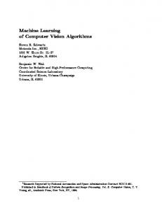
D. Detecting Meaningful Changes Tracking the hand is not su�cient for classifying assembly operations. For example, the hand may follow quite similar trajectories during a pick or a place operation. In theory, measuring precise postures of the ngers might help recognizing grasp and ungrasp operations. But, from our preliminary experiments, we decided that this approach is unrealistic for our purpose. During assembly operations, the ngers are often occluded by or touches the other objects. So it is very di�cult to reliably measure the 3D positions and postures of all the ngers in real time using vision. Alternatively, we pay attention to a manipulated object and its neighbors. Every meaningful assembly operation changes the state of those objects. And such changes are generally easier to detect by vision. D.1 Detecting Qualitative Changes. Pick and place operations move objects from one place to another. So, if we restrict our attention to a spatial region which contains an object being picked up or a region where a grasped object is to be placed, we can de ne three types of qualitative changes for classifying operations: (1) An object has disappeared, which means the object was picked up. (2) An object has appeared, which means the object was placed. (3) No change, which means the hand has approached an object or the worktable, or even touched it, but did neither pick nor place. These events can be detected by di�erentiating two snapshot images of the target region extracted at the start and the end time points of an operation. We implemented this method as a \change-detector". The change-detector returns either of the three qualitative values (appeared, disappeared, no-change) based on image subtraction and area thresholding. In addition, the detector returns a 3D measurement of the center of changed area based on stereo triangulation. Aligning two faces to achieve a coplanar state is one of the important ne operations in assembly tasks. We developed a \coplanar-detector" which extracts edges from a local region around the two faces and checks for characteristic types of junctions (Fig. 5) which only occurs in the coplanar state. 5 This function is not used in our current system, because it is useless when the hand rotates around the vertical axis.
KUNIYOSHI, INABA AND INOUE: LEARNING BY WATCHING
E1
E2
E1
E3
E2
E3
Non-coplanar
E1 E3
E3
7
E2 E3
Non-coplanar
Coplanar
Fig. 5. Characteristic features (in round boxes) of coplanar/noncoplanar relations.
E. Guided Visual Search. In order to detect a change, it is important to nd the target region of an operation and take the rst snapshot before the hand or the object being held actually touches the target. In other words, controlling the visual attention in time and space is crucial for snapshot based change detection. The timing control is done as a part of a \temporal segmentation" procedure in the higher recognition process (see Section V-A), based on a qualitative change of the hand movement and the guided visual search described below. The spatial control is done by a guided visual search. It is a procedure which detects the target of an operation before the operation completes.
A 1
2
3
B
Fig. 6. Guided Visual Search. A: When the hand is empty. B: When the hand is holding a block. 1{3: Temporal order.
2.
3.
Based on the velocity and pose of the hand, determine a search orientation in which the target of operation is likely to be found. A step length is de ned as the segment a line of the search orientation intersecting with the attention region. Prepare a search step vector with the chosen direction and length 8 . The vector is projected for the right and left views to set the 2D search step vectors. Setup a termination condition. In the environment model, compute the distance between the initial point and the surface of the worktable9 in terms of the number of search steps. Choose the minimum of the step count and a xed preset limit10 . Store it as the cycle limit. Search.
Repeat moving the sil- nder windows by the 2D search step vectors until either, (a) the sil- nder reports an existence of a silhouette, or (b) the number of cycles exceeds the limit (Fig. 6(2)). If the cycle is terminated due to Condition (a), proceed to Step 3. Otherwise, just return control to the higher process. In the latter case, no event is generated and the temporal segmentation cue (qualitative movement change) is discarded. Post processing.
Something was found, so look it up in the environment model: Set the attention region at the reported 3D position, and nd an object model which intersects with the attention region. If no object model is found, just return control to the higher process. The visual cue which is not con rmed by the environment model is thrown away. If an intersecting object model is found, report to the higher process that the target of operation is found. Then place a snapshot region according to the current state of the hand: (a) If the hand is empty, set the region to cover the target object (Fig. 6 (A-3)). (b) Otherwise, set the region at the place just above the found target with the approximate size of the grasped object (Fig. 6 (B-3)). This procedure uses simple visual cues for speedy detection, spatial information from the environment model for guiding the search and con rmation, and temporal context from the action model for correct setting of the attention region. The e�ectiveness of the method is based on the on-line update of the environment model and the action model to re ect the current task state. The entire visual search procedure takes about 200{300 msec.
The procedure uses both visual information and the environment model. It consists of the following steps: 1. Initial setup. Set a virtual 3D attention region at the current position of the hand in the environment model (Fig. 6(1)). The region is chosen as: (a) A default rectangular IV. Structure of the Action Recognizer prism6 , if the hand is empty, or else, a circumscribed The action recognizer consists of an action model, an box of the grasped object7 . Instantiate a sil- nder and send it an \:attention" message with the 3D attention environment model, and an attention stack (Fig. 7). The region. 8 In our current implementation, the direction is xed as perpendic6 Currently, 50mm(W)250mm(D)245mm(H). ular downward and so the magnitude is set as the vertical length of 7 The fact that the hand is or is not holding an object is re- the attention region. 9 The table is painted black and therefore invisible. trieved from the environment model as a result of recognizing pre10 Currently set to 4. vious actions.
8
IEEE TRANSACTIONS ON ROBOTICS AND AUTOMATION, VOL. XX, NO. Y, MONTH 1994 Action Model Transfer1 (REACH)
LocalMotion1 (PICK)
Attention Stack
Task1
JN
LocalMotion2 ( )
FR LM FM DA
World1
HandLoc1
Finger1
Approach1 ( )
Transfer2 (REACHWITH-OBJ)
Environment Model
Anticipation FineMotion
: history : subnode links
:attention pointers
Loc2
Loc1
Table1
Block2
Block1 Events: JN:Join, FR:Far, LM:Large-motion, FM:Found-moving, DA:Disappeared
Fig. 7. Structure of the Action Recognizer. TABLE II
World HandLoc
Table Loc
Finger
Block
Fig. 8. Environment model node (ENV-node) classes. Hierarchical levels are denoted by solid horizontal lines. Possible subnode relations are denoted by dotted arrows.
entire system is implemented by object-oriented programming. Each primitive element (node) of the recognizer is implemented as an object with internal state and associated methods (embedded procedures). Most of the processing is done by passing messages among the nodes.
A. The Environment Model The environment model consists of partial description nodes (ENV-nodes) which form a coarse to ne hierarchy. During action recognition, the nodes and the connecting links are dynamically generated or updated to re ect the current state of the workspace. The types of nodes, possible links between them, and the levels of hierarchy are shown in Fig. 8. A dotted arrow in the gure means there can be a \subnode" link which represent a positional dependency between the two nodes, e.g. holding, supporting, etc. Figure II shows an example of an instantiated ENV-node (HandLoc). Each node has slots for current position (position), a geometric model of the describing region (geomodel), and links (parent and subnodes) to other nodes. The event-table translates each incoming event query to a self method call which interrogates a VFD, interprets the obtained data using current state description and then, depending on the result, return a qualitative event. The detector-table associates each event detection method to a VFD, which is dynamically generated by the ENV-node. Table III lists the currently de ned visual events. The description is partial in the sense of spatial extent, coarseness, and types of information. The class \World" represents the whole workspace coarsely, using only the
Slots and contents of an instantiated ENV-node. All the numerical data are in mm.
slot type name parent subnodes position geomodel attention-region attention-nodes event-table detector-table relation
content HandLoc HandLoc1 World1 (Loc1) #f(138 225 174) 50(W)250(D)245(H) prism rectangular prism (NR, SM) :Near ! :visual-search :Small-motion ! :motion-feature :visual-search ! sil- nder :motion-feature ! hand-tracker (holding Loc1)
\HandLoc", \Loc", and \Table" nodes as entries. An object- nder and a motion-detector is associated with this node. The \HandLoc" (Table II) represents a simpli ed concept of the hand, e.g. its spatial extent, the position and the velocity of the hand, and whether it is holding an object. Here, we assume the sole function of the hand is to grasp objects. So we de ne the center of the hand at the middle point between the thumb and the index nger (the position of the holder-detector in the hand-tracker). Also, we use a rectangular prism with its center placed at the center of the hand to represent its spatial extent. Its size is not very important, since it is used only as a default attention region representing uncertainty for visual search procedure described in Section III-E. The HandLoc node computes qualitative motion feature values using 3D velocity data from the hand-tracker. The values and thresholds used are shown in Table IV11 . One of 11 In our current system, VL 1 = 10; VH 1 = VL 2 = 50; VH 2 = 10000 [mm/s]. And AD = 75; AU = 120[deg], both angles measured from a perpendicular downward orientation.
KUNIYOSHI, INABA AND INOUE: LEARNING BY WATCHING
9 TABLE III
Qualitative visual events. Each event is detected by a corresponding ENV-node using the specified detector.
Event Type
Meaning
Detector
:Loc-exist identify and locate objects :Found-moving a moving target (Hand) is found inside base (World) :Disappeared target (Hand) went outside of base (World) :Large-motion base (Hand) is moving fast :Small-motion base (Hand) is moving slowly :Near base (Hand) is near some target (Blocks) :Far base (Hand) is far from target (speci ed blocks) :Join base touches target (speci ed blocks) :Split base separates from target (speci ed blocks)
object- nder motion-detector
Env. model node responsible World World
hand-tracker
HandLoc,World
hand-tracker hand-tracker visual-search
HandLoc HandLoc HandLoc, Loc
hand-tracker
HandLoc, Loc
hand/object-tracker
HandLoc, Loc
hand/object-tracker
HandLoc, Loc
TABLE IV Qualitative motion feature values and their thresholds. VL = lower threshold for speed, VH = higher threshold for speed, AD = threshold angle for downward, AU = threshold angle for upward.
value :Staying :Moving-up :Moving-down :Moving-laterally :Moving-Fast
speed v < VL VL < v < VH VL < v < VH VL < v < VH VH < v
direction | AU < a a < AD AD < a < AU |
Task BUILD
Transfer
LocalMotion
REACH REACH-WITH-OBJ WITHDRAW
PICK PLACE-ON-TABLE PLACE-ON-BLOCK NO-OP
Approach
FineMotion
Depart
APPROACH APPROACH-WITH-OBJ
GRASP RELEASE ALIGN
DEPART DEPART-WITH-OBJ
Fig. 9. Assembly motion classes (boxes with bold labels) and associated operations.
the two di�erent speed range, VL 1 < v < VH 1 or VL 2 < v < B. The Action Model VH 2 , can be selected by sending either :Small-motion or The \Action model" is a collection of nodes (henceforth, :Large-motion as an event query message to the HandLoc ACT-nodes) which represent temporal structure of assemnode. bly actions. The \Loc" represents a partial state of a place which contains one block. Its geomodel is a rectangular prism B.1 Classi cation of Assembly Actions. We classify assembly operations by following two stages: which encloses the block. It describes position, size, and First, de ne \assembly motions" which characterize cersupport relations, but no orientation. tain temporal extents based on temporally continuous feaGeometrical models for \Block" nodes are chosen by tures such as movement and relative positions. Second, for the initial state recognition process from a shape database each \assembly motion", de ne a set of \assembly operawhich is provided manually. And their positions and ori- tions" which characterize the e�ect of the motion based on entations are initialized by the object- nder. Currently, changes or invariants in the environment during the given nger models are not used since we do not have reliable temporal extent. The assembly motion classes and assemmeans to visually track the ngers in real time. bly operations de ned in our system is shown in Fig. 9.
10
IEEE TRANSACTIONS ON ROBOTICS AND AUTOMATION, VOL. XX, NO. Y, MONTH 1994
Currently, assembly motions are characterized by the qualitative motion features (Table IV) of the hand and the relative location of the hand with regard to the target objects. As shown in Fig. 9, we have a class hierarchy de ned by inclusion relations between the temporal extents of assembly motions. The \Task" is an abstract class which covers a whole temporal extent of one task. There are two types of basic assembly motions: (1)\Transfer" { A large movement of the hand in free space, and (2)\LocalMotion" { A slow, upward/downward hand movement near speci c target objects. \LocalMotion" is further resolved into three types of assembly motions: (1)\Approach", in which the ngers and the grasped object move toward the target objects, (2) \Depart" is the reverse motion to Approach, and (3) \FineMotion", the duration between \Approach" and \Depart", e.g. grasping/releasing, or the held object moving in contact with the target objects. An assembly motion is classi ed into several operations depending on the change/invariant during the temporal extent, as shown in Table V. In our current system, a \Task" is always classi ed as a generic \BUILD" operation. It is used to bind the entire action model and to record the initial and the nal task states. \Transfer" is classi ed into three types of operations: \REACH" (move an empty hand to a block), \REACHWITH-OBJ" (move a grasped block elsewhere), and \WITHDRAW" (retract the hand after an operation). \LocalMotion" is classi ed as \PICK" (pick up a block from the table), \PLACE-ON-TABLE" (put a block down on the table), \PLACE-ON-BLOCK"(put a block on (an)other block(s)), or \NO-OP" (did neither PICK nor PLACE). Our current system handles only one meaningful operation for \FineMotion". It is \ALIGN" (move a block in contact with another to align their side faces). B.2 Structure of Action Model Nodes (ACT-nodes). Prototypical nodes (class nodes) of the action model provide hand-coded knowledge used for action recognition. They are implemented as EUSLISP object classes corresponding to assembly motion classes. They are instantiated during recognition process to represent actual actions. An example instantiated ACT-node is shown in Table VI. Each ACT-node has pointers to related ENVnodes: base always contains the subject of the current motion (e.g. the hand or the grasped object), target contains the target of the operation (e.g. the object to be picked up, or the object on which the current grasped object is to be placed), special contains relevant objects which are neither base nor target, typically, a grasped object. The parent/subnode pointers represent temporal embedding of coarse and ne actions. In order to record the result of recognition, following slots are used: The initial/ nal-event slots for recording the segmentation events, the initial/ nal-state slots for snapshot copies of the corresponding ENV-nodes at the beginning
TABLE VI
Example of an instantiated ACT-node: LocalMotion2. All the slots are filled just for explanatory purpose. This does not correspond to any momentary state during recognition.
slot type name parent base target special subnode history initial-event nal-event initial-state nal-state operation
content LocalMotion LocalMotion2 Task1 HandLoc1 Loc2 Loc1 Depart2 (Approach2, FineMotion2) :Near (time t1 ) :Far (time t2 ) copy of (HandLoc1, Loc2, Loc1) at t1 copy of (HandLoc1, Loc2, Loc1) at t2 PLACE-ON-BLOCK
and the end points of an action, the operation slot stores an identi ed operation type, and the history records a temporally ordered list of previous sub-actions (e.g. history of subnode contents). As a collection of methods, each class node describes a mapping from change/invariants to corresponding operation types, previously given in Table V. A class node also has a table which maps incoming events to their interpretations. An interpretation is a list of one \action transition speci cation" and any number of \attention redirections". An action transition speci cation consists of (1) a transition direction, (2) the next action class, and (3) related ENV-nodes for the next action. A transition direction instructs the toplevel recognition process to manipulate the links and nodes of the action model. The direction may be either \:next", \:down" or \:up" | \:next" instructs to terminate recognizing current action and generate a new ACT-node within the same hierarchical level, \:down" instructs to generate a subnode (if there is already one, terminate it an replace by the new node) for an embedded ner actions while retaining the current node, and \:up" instructs to terminate recognizing the current action, and truncate the subnode link of the parent node. Here, the \current node" denotes the one which received the original event. Transition speci cations used in our current system is shown in Table VII. The \attention redirections" are described later in this section. B.3 The Attention Stack. The \Attention stack" is a key component for relating the action model and the environment model dynamically under the context of action recognition. It realizes a limited activation of the models for e�ciency and hierarchical concurrent processing for robustness. Only the model nodes
KUNIYOSHI, INABA AND INOUE: LEARNING BY WATCHING
11 TABLE V
Classification of assembly operations. Each motion is classified using the feature values to one of the corresponding operations. Hold = True iff the Hand is holding a block. SilDiff = temporal difference of silhouette based subimage snapshots. CoplDet = temporal difference of truth values (True = 1, False = 0) meaning whether coplanar edge junctions were found.
motion class Task Transfer
feature type(s) none (SegEvent, Hold)
LocalMotion
SilDi�
Approach
Hold
Depart
Hold
FineMotion
CoplDet
feature value
operation type BUILD (:Near,:False) REACH (:Near,:True) REACH-WITH-OBJ other WITHDRAW :decreased PICK :increased PLACE-ON-TABLE PLACE-ON-BLOCK :no-change NO-OP False APPROACH True APPROACH-WITH-OBJ False DEPART True DEPART-WITH-OBJ :Positive ALIGN other NO-OP TABLE VII
Mapping from events to next actions and ENV-nodes. ColdBoot means the initial startup of the system. The event :Loc-exist segments only a perceptual action. Pointers in base and target are retained unless explicitly modified.
motion type ColdBoot Task
event :True :Loc-exist :Found-moving
transition | | :down
next motion Task | Transfer
Transfer
:Disappeared :Near
:up :next
| LocalMotion
LocalMotion
:True
:down
Approach
Approach Depart FineMotion
:Far :Join :Join :Split
:next :next :next :next
Transfer FineMotion FineMotion Depart
selected from the attention stack become active. These nodes are also processed concurrently. The stack has several levels corresponding to the hierarchy of assembly motion types. Each level of the stack can hold one or more \attention nodes" (henceforth, ATTN-nodes). They represent the current expected events, links to corresponding ACT/ENV-nodes (denoted by thin arrows in Fig. 7), and temporary memory for detected events with feature values. An ATTN-node has two methods: (1) \:Detect" generates a message containing an expected event name and a list of pointers to the related ENV-nodes. Then it sends
new base World base target
(= Hand) | base
(= Hand) base special base base base base
new target | Loc's found. | | Loc's found. (= objects near) target target
|
target target target
the message to the connected ENV-node. Upon receipt of a response from the ENV-node, the ATTN-node records the result. (2) \:Analyze" sends the recorded event type and the feature value to the connected ACT-node. The response from the ACT-node is returned to the issuer of the \:Analyze" message (e.g. the toplevel process). Each ACT-node has a mapping from incoming events to necessary \attention redirections", as shown in Table VIII. An \attention redirection" is a list of a stack operation, a new event name, a new base node and new target nodes. The stack operation may be either; \:add"{ create a new
12
IEEE TRANSACTIONS ON ROBOTICS AND AUTOMATION, VOL. XX, NO. Y, MONTH 1994 TABLE VIII
Mapping from incoming events to attention redirections; stack operation (op), next event, new base, and new target. Coded in ACT-nodes. \:Init" denotes the initial attention specifications for each ACT-node. Pointers in base and target are retained unless explicitly modified. Automatic redirections during action segmentations are not listed in this table.
motion Task (base= World) Transfer (base= HandLoc) LocalMotion (base= HandLoc) Approach Depart FineMotion
event :Init :Loc-exist :Found-moving :Init :Staying :Moving-down :Init :Init :Init :True :Init :Init :Init
op :add :reset :add :add :add :add :add :add :add :delete :add :add :add
ATTN-node and add it to the current level of the stack (if there is already another node with the same event name, replace it by the new one), \:reset" { pop all the nodes on the stack down to the current level and place a new node there, or \:delete" { delete the speci ed ATTN-node. Besides the explicit attention redirections, when an action transition has occurred, an automatic attention redirection is simultaneously done by the toplevel process: A \:reset" operation is issued for the stack level corresponding to the new action, placing a new ATTN-node created according to the \:Init" attention redirection of the new ACT-node. V. Recognition of Action Sequences
The role of the action recognizer is to observe the continuous performance of a task and generate a symbolic description of the sequence of operations. In order to do this, the recognizer must rst detect those points in time when one action ends and the next action begins. Secondly, the recognizer must identify each temporal period as one of the known operations. Such processing is called temporal segmentation and action identi cation. We do not want to store the entire image sequence and then spend hours analyzing it o�-line. Therefore, the processing must be reliably done on-line and in real time.
A. The Detect-Analyze Loop. The main part of the top level algorithm for action recognition is a detect-analyze loop described below. The detect loop and the analyze loop are executed alternately to simulate parallel processing. Example behavior of the action recognizer during an action transition from a Transfer to LocalMotion will also be explained using Fig. 10. Detect: Scan the attention stack from bottom to top, sending a \:detect" message to each ATTN-node. Repeat this step until at least one of the nodes receives
next event :Loc-exist :Found-moving :Disappeared :Small-motion :Near :Near :Large-motion :Far :True | :Join :Join :Split
base
World base base base base base base base base base base base base
target
| HandLoc target
| | | |
target
| |
target target target
an event. A.1 Example. Let us focus on the two ATTN-node labeled \NR" and \FM" in Fig. 10(up). The \NR" node has a link to \HandLoc1". When \NR" receives a \:detect" message, it sends a \:Near" message to \HandLoc1". Then \HandLoc1" sends itself a \:visual-search" message. This invokes a visualsearch procedure described in Section III-E, using the hand-tracker and a sil- nder. The target object \Loc2" is found, and a message containing \(:Near HandLoc1 Loc2)" is returned to the \NR" node and stored there for later processing in the analyze phase. The \FM" node converts a \:detect" message into a \:Found-moving" message and directs it to the \World1" node. Then the \World1" node sends a \:found" message to the associated motion-detector. If the motion-detector has found some movement, its 3D position is returned. Then the \World1" node sends a \:stimulate" message with the detected position to the \HandLoc1" node in order to check if it coincides with the current position of the hand (updated by the hand-tracker). If there is a big di�erence12 between the positions, which means that the hand-tracker is capturing a false target, the \World1" node returns a list of an event label \:Found-moving" and a pointer to the \HandLoc1" node. Otherwise, if no movement was found or the positions are close, \nil" is returned. The result is stored in the ATTN-node \FM". Analyze: Scan the stack from bottom to top for an ATTN-node with a detected event, and if it is found, send it an \:analyze" message. This returns zero or one action transition speci cation and any number of 12 The 3D distance currently set as 120mm.
KUNIYOSHI, INABA AND INOUE: LEARNING BY WATCHING Current state of the Action Model Transfer1 (REACH)
Task1
LocalMotion1 (PICK)
Transfer2 ( )
13
Attention Stack
Current state of the Environment Model
NR SM FM DA
motion -detector
World1
HandLoc1
Loc2
Loc1 Anticipation
Table1
hand -tracker
silfinder
LocalMotion
Transfer1 (REACH)
T FR LM FM DA
Task1
LocalMotion1 (PICK)
LocalMotion2 ( )
Transfer2 (REACHWITH-OBJ)
: already recognized action nodes
Anticipation
motion -detector
World1
HandLoc1
change -detector
Loc2
Loc1
Table1
hand -tracker
Approach
: history
: active links
: activated environment nodes
Events: T:True, JN:Join, FR:Far, SM:Small-motion,LM:Large-motion, FM:Found-moving, DA:Disappeared
Fig. 10. Example states of the action recognizer. Before (up) and after (down) a transition from \Transfer" to \LocalMotion".
attention redirections. Execute them. When the event signals an action segmentation (transition), the following steps are taken: (1) Take a visual snapshot of the region represented by the connected ENV-node. (2) Di�erentiate the speci c features in the initial and the nal snapshots to identify the current operation. (3) Save the current ACT-node with the copied ENV-nodes into memory. (4) Instantiate a new ACT-node and generate new ATTN-nodes. (5) Associate ENV-nodes with the new ACT-node. The ENV-nodes are passed from the previous ACT-node or from the result of attention control, such as visual search. Let us consider the following two cases for the example of Fig. 10. A.2 Case 1: Only \:Near" was detected. This is the case in Fig. 10(down). The result of \analyze" will be one action transition speci cation \(:next LocalMotion base Loc2)" (Table VII). This instructs to invoke the above action segmentation procedure. The current assembly motion \Transfer2" is classi ed according to the Table V as \REACH-WITH-OBJ" and stored into the history of \Task1". A new node, \LocalMotion2", is generated by instantiating a class node \Lo-
calMotion". It is connected as a new subnode to the \Task1". Also, \HandLoc1" is connected to its base and \Loc2" is connected to its target. Then an automatic attention redirection takes place { By a \:reset" command, the nodes \NR" and \SM" are popped away. And the initial attention of \LocalMotion" (\LM", \FR", and \T". See Table VIII) are pushed onto the stack. A change-detector is allocated and an initial snapshot is taken. A.3 Case 2: \:Found-moving" was detected. This case is not shown in Fig. 10. In this case, regardless of whether \:Near" was detected or not, the result of \analyze" will be one action transition speci cation \(:down Transfer target nil)" (Table VII) and one attention redirection \(:add :Disappeared base target)" (Table VIII). The action transition means to generate a new subnode of \Task1". So, the \Transfer2" is terminated, its operation identi ed as \WITHDRAW" (Table V) , and stored in the history of \Task1". A new ACT-node, \Transfer3", is generated with a pointer to the HandLoc in its base slot, and connected to the subnode of \Task1". By an automatic redirection, the ATTNnodes \NR", \SM", \FM" are popped from the stack. Then the initial attention of \Transfer3", \SM" (Ta-
14
IEEE TRANSACTIONS ON ROBOTICS AND AUTOMATION, VOL. XX, NO. Y, MONTH 1994 ble VIII), is pushed onto the stack. Finally, the explicit redirection is executed: the \DA" is replaced by a new one (\DA").
B. Recognition Flow of Pick and Place Sequence A typical recognition process for a \PLACE" operation is shown in Fig. 11. The top horizontal arrow (\Scene") shows the time axis with scene descriptions. The \Vision Process" lines represent continuous vision processes executed in parallel. The marks on the \Events" line show the time when various events are raised. Thin arrows connect the events and corresponding e�ects. Intervals on the \Motion" lines denote segmented assembly motions. Two types of \Snapshot"s at the segmentation points and their \Change"s are given. The \(Sil.)" snapshots are gray scale silhouettes. The \(Junct.)" snapshots are the connectivity of local edges near the target faces of objects.
Recognition of Transfer motion:
Firstly, a motion-detector is invoked. When a large movement is detected, the event \:Found-moving" is raised, signaling the start of a \Transfer" motion. At the same time, the hand-tracker is invoked to track and extract motion features. For explanatory purposes, we assume that one PICK operation is completed and another Transfer motion is started in the breaks marked by waves in Fig. 11. Initial point of LocalMotion: When the hand starts to move slowly downwards, the event \:Movingdown"(:Small-motion), is raised. This event invokes a visual search procedure. When the target object is found, the event \:Near" is raised. This signals the end of the \Transfer" motion and the start of \LocalMotion". Based on the prior recognition of a PICK, the ENV-node \HandLoc" records that the hand is holding an object. So, the attention of the change-detector is directed to the expected PLACE position. Final point of LocalMotion: The hand starts to move again. Once it gets far enough away from the target objects, the event \:Far" is established. This event signals the end of the \LocalMotion" and the start of next \Transfer". The change-detector extracts another snapshot and then nds that the area of the silhouette has increased. This results in the identi cation of the operation as a \PLACE-ON-BLOCK". Updating the environment model: The environment model is updated to re ect the new state of the environment. The \holding" relation between the hand and the placed object is deleted. An \on" relation between the placed object and the target object is added. The target position of the operation is estimated by measuring the center of area from the differentiated stereo images13 . Based on the knowledge that the operation was a \PLACE-ON-BLOCK" and the dimensions of objects in the model, the vertical position of the placed object is recomputed and stored. Copies of ENV-nodes corresponding to the hand and 13 This method sometimes su�ers measurement errors due to
occlusion.
the objects are made, and are stored in the nal-state slot of the current action model node. Recognition of FineMotion: A ner level of recognition proceeds in parallel with the \LocalMotion". The relative position of the held object and the target object is continuously monitored by vision. When they touch each other, the event \:Join" is established which signals the start of \FineMotion". A coplanar-detector is invoked and gives a result \No Coplanar", because faces of the objects are not aligned at the beginning of the \FineMotion". When the ngers release the placed object14 , the event \:Split" is established, signaling the end of \FineMotion". This time, the coplanar-detector nds the \Coplanar" state. Di�erentiating the initial and the nal states, the \FineMotion" is identi ed as an \ALIGN" operation. The coplanar relation de nes the relative orientation of the objects, which is then recorded in the environment model. The hierarchical parallelism contributes to robustness. Even when the hand suddenly moves o� during a FineMotion, the system quickly catches up with the gross motion. The attention stack extends at important points and winds up elsewhere, thus dynamically controlling the depth of the recognition process. VI. Dependency Analysis of Task Structure
The action recognition process presented in the previous section outputs symbolic descriptions of action sequences. Information about the ordering and the dependency within a task can be attained by analyzing the observed action sequences. This knowledge is useful when the need arises to reorder or modify the sequence. This will greatly contribute to increasing the reusability of the result.
A. Representation of the Task Plan A.1 Input: Sample output from the action recognition procedure is shown in Fig. 12. In this task, a structure with an inverted arch balanced on a center pillar is built. The intermediate states at the start and end points of each action (IS, FS) are remembered as partial snapshot copies of the environment model. A.2 Output: An example of a higher level task description generated from the sample action sequence is illustrated in Fig. 13. A hierarchical task plan is represented in terms of state change operators (round boxes), subtask links (solid straight lines), and dependency links (arcs for non-ordered sequences and arrows for ordered). The hierarchical levels of the plan are divided into upper and lower parts at the 14 Our current system does not track the ngers precisely. There-
fore, the detection of \:Split" is based on comparing the positions of the hand and the target location. As a result, the event \:Split" is unreliable. But this does not a�ect recognition severely, because the termination of the FineMotion is forced by the upper level events, \:Far" or \:Found-moving".
KUNIYOSHI, INABA AND INOUE: LEARNING BY WATCHING Hand comes in.
15
Moving slowly downward.
Moving fast.
Scene
Placing the block.
Moving away.
t Motion detection
Vision Process
Tracking Hand Search down
Found-moving
Small-motion Moving-down
...Hand and the blocks.
Measure distance between ... ...blocks. ...finger and the placed block.
Near (Target found.)
Join
Split
Far
Events Motion (segmented)
Transfer
Transfer
LocalMotion Approach
Depart
FineMotion
Snapshots (Sil.) Change (Sil.)
OP=PLACE-ON-BLOCK
increased
Snapshots (Junct.)
No coplanar
Coplanar
Change (Junct.) Coplanar established
OP=ALIGN
Fig. 11. Recognition ow of PLACE operation.
(reach01 pick01 reach-with-obj01 place-on-table01 reach02 pick02 reach-with-obj02 place-on-block01 reach03 no01 reach04 pick03 reach-with-obj03 place-on-block02 reach05 pick04 reach-with-obj04 place-on-block03 withdraw01 withdraw02)
B 03 b:1,2,3,4 t:0
SC -
3
Fig. 12. Recognized action sequence.
B 02 b:2,3,4 t:1
object state level(OSL), where the state of only one object is changed per unit operation. Fig. 13 shows only the upper part. A.3 Operators: The classes of general operators are given a priori. We de ne only one class, \ACHIEVE" for OSL operators. An ACHIEVE manipulates one object and establishes relations with other object(s). Operators at the lower levels are labeled as FETCH, PUT, or FAKE (meaningless operation). Upper level operators are called PACHIEVE (ACHIEVE while keeping special relations), or BUILD (put together several blocks). In Fig. 13, operator classes are indicated by initial letters (A(chieve), P(achieve), B(uild)). A summary of the contents of PACHIEVE01 generated by our system is shown in Fig. 14. The operator description consists of three major components: (1) Focused Objects: base (manipulated objects), target (objects concerning new relations established by the operator), special (objects associated with the base by relations maintained by the operator). (2) State Changes: SC+ (newly established relations), SC0 (removed relations), SI (unchanged relations), SP (speci cally maintained relations). Each slot contains a list of support relations among objects described in terms of symbolic descriptor and relative coordinates. (3) Subpro-
2 1
P01 3 4 b:2 2 1 t:1 s:3,4
B 01 3 4 b:3,4 2 t:2
A 01 b:1 t:0
1 0
A 02 3 b:3 2 t:2
A03 b:4 t:2
SC +
4
4 2
A04 b:2 t:1
2 1
Fig. 13. Generated task plan.
cedure (plot): A procedure for achieving the state change of this operator. Described in terms of a partially ordered set of lower level operators. In Fig. 13, focused objects slots are denoted as 'b:', 't:', 's:'. For the topmost operator BUILD03, the graphics of the state changes, SC0 and SC+ , are displayed. They are generated from the environment model. For other operators, only SC+ is shown as schematic displays. Arrows denote the ordering of procedures and arcs denote the parallelism.
16
IEEE TRANSACTIONS ON ROBOTICS AND AUTOMATION, VOL. XX, NO. Y, MONTH 1994 slots class name type base target special SC
+
SC
0
SP
SI
plot next
contents PACHIEVE PACHIEVE01 instance (planar-brick2) (short-brick1) (medium-brick3 medium-brick4) (planar-brick2 on short-brick1 :at #f(-16.0 1.8 37.7) :wrt short-brick1)) (planar-brick2 on table0 :at #f(121.0 284.3 12.7) :wrt table0) (medium-brick3 on planar-brick2 :at #f(-16.5 15.3 42.7) :wrt planar-brick2) (medium-brick4 on planar-brick2 :at #f(34.3 -42.4 42.7) :wrt planar-brick2) (medium-brick3 on planar-brick2 :at #f(-16.5 15.3 42.7) :wrt planar-brick2) (medium-brick4 on planar-brick2 :at #f(34.3 -42.4 42.7) :wrt planar-brick2) (short-brick1 on table0 :at #f(-20.7 126.6 25.0) :wrt table0) ($action achieve04) nil
Fig. 14. Generated PACHIEVE operator.
B. Gathering State Changes and Determining Focused Objects
ACHIEVE: FETCH: PUT: FAKE:
FETCH,FAKE*,PUT REACH,PICK,WITHDRAW* REACH-WITH-OBJ, fPLACE-ON-BLOCKjPLACE-ON-TABLEg, WITHDRAW* fREACHjREACH-WITH-OBJg,NO,WITHDRAW*
Fig. 15. Templates for xed order procedures. Upper level operators in the left column are expanded into partial sequences of lower level operators in the right column. '*' denotes repeating more than zero times. fajbg denotes selecting either 'a' or 'b'.
appear in the newly generated state change description: Let obj + and obj 0 denote the sets of objects appearing in SC+ and SC0 , respectively. base = obj + \ obj 0 ; target = obj + 0 base
B.3 Extracting Protected Conditions: A set of relations SP which must be held (protected) during the application of an ACHIEVE operator, and the related set of objects (labeled special) is obtained as follows: SP = SI \ frel(x; y ) j (x 2 base _ y 2 base)g; special = fxj9rel(x; y) 2 SPg 0 base
The plan analysis process described in section VI-C proFig. 13 shows how the state changes and the focused ceeds in a bottom up manner by organizing mutually deobjects (illustrated with solid lines) are gathered as the pendent input operators into a partial procedure, and then plan analysis process builds up the hierarchical plan. relating it to a newly generated upper level operator. In the course of this analysis, the contents of the upper level operator are calculated from those of the constituent lower C. Generating a Hierarchical Plan by Task Procedure Analysis operators. C.1 Step 1 { Analyzing Fixed Order Procedures: B.1 Gathering State Changes: In the assembly plan below the OSL, xed patterns of Firstly, state change descriptions for each input operator the partial operator sequences appear repeatedly. Thus, we which initially has only the intermediate state descriptions can provide to the system a set of templates for the paris calculated as follows: tial sequences. The templates are described by the regular expressions shown in Fig. 15. Identi cation of a partial + 0 SC = FS 0 IS; SC = IS 0 FS; SI = IS \ FS procedure and relating it to an upper level operator is carNext, the state change for an upper level operator OPi ried out by matching the sequence with the templates by an is calculated from lower level operators fOPj g in the plot ATN (Augmented Transition Network) interpreter [28]. At the end of this step, the whole input sequence is organized (subprocedure) slot of the OPi: into a set of ACHIEVE operators. 0 SC+ i = SC+ j C.2 Step 2 { Analyzing Dependencies: j 0 Dependency among operators above the OSL are anaSC0 j SC0 i = lyzed by tracing the coincidence of focused objects. j An operator OPi moves the objects included in its base SIj SI0i = slot. When an operator OPj establishes some new relations j at an arbitrary time in the future, the set of objects con0 0 + + 0 tained in the base and the target slot of the OPj serves as SC i = SC i 0 SC i 0 0 a \support", or a domain, of those relations. At this time, SC0 i = SC0 i 0 SC+ i the objects in the base of OPj are moved but those in the 0 0 0 0 SIi = SI0i 0 SC+ i 0 SC0 i + (SC+ i \ SC0 i) target are not. Thus, we can state that if base(OPi) \ target(OPj ) 6= � B.2 Determining Focused Objects: then the validity of the OPj depends on that of OPi . We The contents of the base and the target slots of the upper call this type of dependency \B-T relation" (base-target level operator are obtained by screening the objects which relation).
[ [ [
KUNIYOSHI, INABA AND INOUE: LEARNING BY WATCHING 5 4 3 2
1
A01 b:2 t:0
A02 b:1 t:0
A03 b:3 t:2
A04 A05 b:4 b:5 t:1,3 t:4
0 Start
A01 A03 A02
A04 A05
End
($sequence ($parallel ($sequence A01 A03 ) A02 ) A04 A05 )
17 build03: achieve01: build02: build01: pachieve01: achieve03: achieve02: achieve04:
($sequence ($action achieve01) ($action build02)) ($sequence ($action fetch01) ($action put01)) ($sequence ($action build01) ($action pachieve01)) ($parallel ($action achieve03) ($action achieve02)) ($action achieve04) ($sequence ($action fetch03) ($action put03)) ($sequence ($action fetch02) ($action put02)) ($sequence ($action fetch04) ($action put04))
Fig. 17. Contents of plot slots of generated operators for the example task.
Our plan analysis method extracts high level task structures from observed operation sequences. Each operator in Fig. 16. Extraction of a partially ordered mutually dependent pro- the input sequences describes only very simple changes in cedure by searching for a B-T transitive closure. terms of relations between a hand and an object. By applying the plan analysis, a spatio-temporal range of descripLet us see an illustrative example: An object A is placed tion is automatically expanded. In the topmost BUILD (OP 1 ) at a certain point in time and then after several operator, descriptions of focused objects, state changes, other objects has been moved, an object B is placed on A and procedures over the whole task are summarized in one (OP 2 ). In this procedure, the OP2 depends on the OP1 place. The method only requires a small amount of a priori and therefore the ordering of the two operators cannot be knowledge and a small amount of computational time. changed. By extracting a transitive closure of B-T relations, a partial procedure connected by the dependency can be identi- VII. Instantiation of a Task Plan in a Different Environment ed. Fig. 16 illustrates an application of this method. The example task is to build the structure shown in the upper In contrast with the teaching data from the traditional left corner. The task is accomplished by the sequence of teaching by guiding, the result of \Learning by Watching" ACHIEVE operators displayed on the right hand side. The has a symbolic structure. This means that the system can middle row of Fig. 16 is the transitive closure extracted by make partial modi cations to the teaching result, thereby searching backward from the maximum ACHIEVE05. This instantiating it in a di�erent environment. graph means that a partially ordered procedure in which the two parallel subprocedures A01 ; A03 and A02 are exe- A. Matching the Task States Between Teaching and Executed in an arbitrary order followed by the sequential subcution procedure A04 ; A05 . This sequence is internally represented In the current implementation, we assume that the iniusing grammatical notations as shown in the bottom row tial positions of parts di�er between teaching and execuof Fig. 16. tion, whereas the nal position of the complete assembly Similarly, a B-S relation de ned by base(OPi ) \ structure is the same in the world coordinates xed on the special(OPj ) 6= � indicates a type of dependency where worktables. Also, we assume that the parts used for the the object placed by the OPi is carried by the OPj nal assembly have exactly the same shapes between teach(PACHIEVE). ing and execution. There can be irrelevant objects not used Also, a C-T relation de ned by in the nal structure both in teaching and execution. It follows from the above rst assumption that, in world base(OPi ) \ special(OPj ) 6= � coordinates, the goal positions of the PICK operations indicates the parallelism of OPi and OPj . This is where must be modi ed according to the given initial state, but more than two objects are assembled on one common ob- PLACE operations need not be modi ed. Transformation from the world coordinates to the arm coordinates is always ject. Starting from the ACHIEVE sequence generated by Step necessary. The goal positions of the PICK operations are deter1, the plan analysis process searches for each type of tranmined by matching the initial positions of every object besitive closures in the order of C-T, B-T, B-S, B-T. When a tween the teaching and execution environments. closure is found, an upper level operator is generated with The initial state matching is done follows: its plot containing the closure, the focused objects and state changes (as described in section VI-B). In the case of an as1. Initialize the environment model by copying the sembly task in which a connected graph is built, the whole recorded initial state of the teaching phase. procedure is connected by dependency relations. Such a 2. Refer to the task-level plan generated by the plan anplan is integrated into one BUILD operator by the above alyzer and get a list of objects (ENV-node name and described procedure. shape name) used for the nal assembly. Irrelevant obThe plots of the operators from the example task of jects in the teaching environment are ignored in this Fig. 13 are shown in Fig. 17. step.
18
IEEE TRANSACTIONS ON ROBOTICS AND AUTOMATION, VOL. XX, NO. Y, MONTH 1994
TABLE IX 3. Using vision (an object- nder), create a temporary Expansion of pick and place actions to robot commands. environment model for the current workspace state. 4. Do a 2-stage match from the temporary model through the list of objects to the environment model, action expansion using shapes as keys. This step removes irrelevant obTRANSFER(pos1,pos2) amove(pos1) jects even if they were present in the execution phase. amove(pos2) 5. For each matched object in the environment model, PICK(pos1) open-hand replace the position/orientation data with the current go-pickpos(pos1) state measurement. If there are more than one obclose-hand jects with the same shape, the matching is done in a go-maxheight rst come rst serve manner. As a special treatment, PLACE(pos1) go-placepos(pos1) the HandLoc data is left unspeci ed, and the Table is open-hand instantiated using the calibration data. go-maxheight Then the plan (recorded action model) is executed by subcommand expansion the following procedure: go-pickpos(pos1) z hand-pos z 1. Take the nal record of the action model from the amove(pos1 x,pos1 y,z) teaching phase. Call it a plan. amove(pos1) 2. Trace the temporal evolution of the plan: First, crego-placepos(pos1) z hand-pos z ate a new Task node in an empty action model and amove(pos1 x,pos1 y,z) link the World node in the environment model to its amove(pos1) initial-state. Then, starting from the oldest node in the history list of the Task node, get one ACT-node by another from the plan in a depth- rst manner. For each such node, do the following: (a) If the node is a REACH or a PICK operation, replace its goal position (target node in the nal-state slot for a REACH, and target in the initial-state slot for a PICK) with the current ENV-node with the same name. (b) For any type of operation, generate manipulator commands and execute them. (c) Update the ENV-node so that it re ects the di�erence between the nal-state and the initial-state of the current operation. Correspondence between a node in the current environment model and a node in the initial/ nal-state is done on the name basis. This procedure keeps the environment model to re ect Fig. 18. Task \Build Table". Initial and nal states in teaching (above) and execution (below). the expected task state at the end of each operation during the execution phase. This will be useful for task execution monitoring and failure detection. In the example task presented here, the human instructor placed four upright rectangular blocks as \legs", then B. Generating Manipulator Commands placed a rectangular plate on top of them to construct a Every operation in the task plan is translated into manip- \table". The coplanar-detector was not used in this examulator commands using the macro expansion rules shown ple. in Table IX. The positional parameters calculated in world The initial and the nal states in both teaching and excoordinates are converted into arm coordinates. ecution phases are shown in Fig. 18. The graphics were For simplicity, the arm trajectory is generated in a point generated from snapshot copies of the environment model to point mode. The approach/depart points for pick and during an experiment. It can be seen that between the place operations are set at a constant distance above the teaching and execution, the initial states are di�erent and worktable. the nal states are equivalent. The human instructor performed the task once from the VIII. Experimental Results beginning to the end without pausing. The system autoWe have run our system for simple assembly tasks in matically segmented and identi ed assembly operations in order to test the described algorithms. The background real time. Figure 19 shows snapshots of the monitor display during and the surface of the workspace were painted black and the blocks were painted white. We assume that complete task recognition. Along the bottom lines of the snapshots are messages from the system stating the results of recogocclusion does not occur between the blocks.
KUNIYOSHI, INABA AND INOUE: LEARNING BY WATCHING
19
1
2
3
4
5
6
Fig. 19. Two action recognitions involved in recognizing the task \Build Table": (1)(4) Target region de ned. (2)(5) Di�erentiation. (3) Classi ed \PICK". (6) Classi ed \PLACE-ON-BLOCK". (reach reach reach reach reach
pick pick pick pick pick
reach-with-obj reach-with-obj reach-with-obj reach-with-obj reach-with-obj
place-on-table place-on-table place-on-table place-on-table place-on-block withdraw)
Fig. 20. Recognized operation sequence for \Build Table".
on the four legs. The whole plan is grounded at the level of visually recognized operators (REACH, PICK, PLACE, WITHDRAW). The total number of upper-level operators generated during the plan analysis, which constitute the nal plan, was 17. The elapsed time for this analysis step was less than 10 seconds on a 10 MIPS workstation. In another workspace, same set of blocks are placed at arbitrary positions. The system recognized the initial state by vision. The assembly procedure was re-instantiated for the given initial state. Forty ve manipulator commands were generated from the instantiated plan and were executed to carry out the task. The equivalent \table" structure was successfully constructed. A part of the command sequence is given in Fig. 24. Graphic displays of some of the intermediate states generated during the task execution is shown in Fig. 23. Other tasks recognized successfully by the system include; (1) a pick and a place with an ALIGN operation, (2) building a tower, (3) building an arch, (4) building an inverted arch balanced on a center pillar.
nition. The elapsed time for the task recognition was 3 min. 50 sec., excluding recognition of the initial state. An assembly procedure consisting of 21 operations was recognized. The whole sequence is given in Fig. 20 and detailed descriptions of the nal PLACE operation is given in Fig. 21. In the gures, \Loc" nodes are indicated by their names (e.g. brick187, plate189.). A high level task structure was extracted by applying the plan analysis process to the recognized action sequence. Figure 22 summarizes the topmost two levels of the hierarchical task plan generated by the process. Each generated operators has state change descriptions, but are not IX. Limitations and Future Development shown here. The root operator, BUILD5197, states that building the table requires ve blocks to be put together, The presented implementation has many limitations as which is accomplished by a BUILD5164 operator and an discussed in this section. There are two reasons for this. ACHIEVE4824 operator in this order. The BUILD5164 First, in order to achieve near real time performance with describes a parallel subprocedure for placing the four \legs" a considerably complex system15 using a rather limited by four ACHIEVE operators, which can be executed in any 15 20K lines in object oriented Lisp, plus 10K lines in C. order. The ACHIEVE4824 describes placing the top plate
20
IEEE TRANSACTIONS ON ROBOTICS AND AUTOMATION, VOL. XX, NO. Y, MONTH 1994
Fig. 23. Intermediate states generated during execution.
motion: localmotion305 operation: (place-on-block) |base: hand183 |target: (brick190 brick186 brick187 brick188) |special: plate189 |initial-event: :near |final-event: :found-moving |initial-state: hand183 pos: #f(-41.9 129.9 137.4) with relation: (holding plate189) plate189 pos: #f(0.0 0.0 0.0) with relation: (held-by hand183) brick190 pos: #f(-24.9 178.9 25.0) with relation: (on table182 :at #f(-24.9 178.9 25.0) :wrt table182) brick186 pos: #f(12.5 126.9 25.0) with relation: (on table182 :at #f(12.5 126.9 25.0) :wrt table182) brick187 pos: #f(-73.1 137.3 25.0) with relation: (on table182 :at #f(-73.1 137.3 25.0) :wrt table182) brick188 pos: #f(-42.9 85.7 25.0) with relation: (on table182 :at #f(-42.9 85.7 25.0) :wrt table182) |final-state: hand183 pos: #f(167.5 153.2 125.2) plate189 pos: #f(-25.1 151.0 59.8) with relation: (on-multiple (brick190 brick186 brick187 brick188) :at #f(-25.1 151.0 59.8)) brick190 pos: #f(-24.9 178.9 25.0) with relation: (co-support plate189 :at #f(.1 27.9 -34.8) :wrt plate189) (on table182 :at #f(-24.9 178.9 25.0) :wrt table182) brick186 pos: #f(12.5 126.9 25.0) with relation: (co-support plate189 :at #f(37.6 -24.1 -34.8) :wrt plate189) (on table182 :at #f(12.5 126.9 25.0) :wrt table182) brick187 pos: #f(-73.1 137.3 25.0) with relation: (co-support plate189 :at #f(-48.0 -13.7 -34.8) :wrt plate189) (on table182 :at #f(-73.1 137.3 25.0) :wrt table182) brick188 pos: #f(-42.9 85.7 25.0) with relation: (co-support plate189 :at #f(-17.9 -65.3 -34.8) :wrt plate189) (on table182 :at #f(-42.9 85.7 25.0) :wrt table182)
Fig. 21. Recognized nal \PLACE" operation in task \Build Table". Placing the top plate.
computational resource, we were forced to choose simple algorithm, especially for vision processing.
;;; Top level (Expansion level 0) ($action build5197 :base (plate189 brick186 brick188 brick187 brick190) :target (table182) :special nil :next-action nil :plot ($sequence ($action build5164) ($action achieve4824))) ;;; Expansion level 1 ($action build5164 :base (brick190 brick187 brick188 brick186) :target (table182) :special nil :next-action (achieve4824) :plot ($parallel ($action achieve4748) ($action achieve4679) ($action achieve4610) ($action achieve4541))) ($action achieve4824 :base (plate189) :target (brick188 brick187 brick186 brick190) :special nil :next-action nil :plot ($sequence ($action fetch4773) ($action put4812)))
Fig. 22. Topmost two levels of generated task plan.
GOAL-POSITION #f(-40.1 -31.0 9.8) ARM GOAL POSITION #f(210.5 261.2 150.3) amove #f(210.5 261.2 55.0) open-hand amove #f(210.5 261.2 150.3) close-hand amove #f(210.5 261.2 55.0) GOAL-POSITION #f(-25.1 151.0 59.8) ARM GOAL POSITION #f(301.1 102.6 100.3) amove #f(301.1 102.6 55.0) amove #f(301.1 102.6 100.3) open-hand amove #f(301.1 102.6 55.0)
Second, our main purpose in building the current system was to verify the action recognition algorithm and to demonstrate at least one working example of \Learning by Fig. 24. A part of generated motion sequence for \Build Table". Placing the top plate. Watching" and \Teaching by Showing". Hence we did not put much emphasis on completeness or generality of the overall system.
KUNIYOSHI, INABA AND INOUE: LEARNING BY WATCHING A. Vision Processing
21
relax the black and white constraint, reduce the e�ect of occlusions, deal with multiple independently moving obA.1 Object Center Measurement. jects and achieve on-line registration/correction of objects Some VFDs (object- nder, sil- nder, change-detector) in the environment model. measure an object position (geometrical center) using cenOne possibility will be to use a combination of multiple ter of mass of a binarized area. Reasonable results are 2D features (e.g. color, primitive shape, texture, etc.) to obtained only when the both cameras are at non-special e�ciently index an object in a pre-de ned database. viewpoints. For an irregular shaped object, there is no guarantee that the measurement is useful. A.5 Tracking. This problem is essential to any snapshot view of an The hand-tracker does not fail even when the hand arbitrary object. So, a solution will require use of shape touches many objects in turn. However, it usually fails knowledge obtained either from temporal observation or by in a particular situation { When the hand touches an archmatching to a shape database. like shape of similar size. This is reasonable because the both look similar. Even in such cases, the motion-detector A.2 Occlusions. nds the hand and the hand-tracker recaptures it. This Since the VFDs use binary image features, they are easily combination is quite powerful for our current task environa�ected by occlusions. ment. One problem is that although it rarely fails as a The change-detector is most severely a�ected. Although whole, either one of the windows often loses or oscillates. it can detect qualitative events unless there is a complete Therefore, the reported hand position is not always stable. occlusion, the reported position (i.e. in a PLACE operIt is also clear that this tracker does not function in a ation) sometimes has a signi cant error when the placed realistic environment since each window basically tracks object is partially occluded, or when the object partially binary image features. As an alternative, gray-level coroccludes other previously visible objects. Our current sysrelation is a powerful and simple method16 . We cannot tem corrects the vertical position of the placed object using knowledge about the sizes of the support objects. But there simply use one large correlation window to track a hand, is no justi cation for an o�ine adjustment of the horizon- since it has a concave, variable shape with changing backtal position or orientation. Quickly tting a geometrical grounds. But using them in place of current binary trackers model to local edges after change detection may be useful. will greatly improve the overall robustness and reliability. In addition, we could use a Zero Disparity Filter [30], a method to extract only such image features with zero stereo A.3 Motion Segmentation. disparity. In combination with active control of stereo verOur motion-detector is robust and reliable for the current gence, it has a strong depth selectivity. Therefore it will task environment. But it will break quickly when we try be a powerful tool for tracking in complex environments. to generalize the system. Especially, it will be useless for a moving observer or for a workspace with multiple and/or A.6 Visual Search. complex moving objects. An alternative will be to use opCurrently the visual search discards the visually detected tical ow [29] for motion segmentation16 . It will enable the target unless it is con rmed by the environment model. system to detect independent motion from a moving obThis treatment is justi ed by the assumption that the enserver, segment and classify moving objects more precisely vironment model is correctly initialized and updated by the and reliably, and extract richer movement feature such as action recognition results to keep up with the task states. 3D rotation directly. This assumption makes the system fragile against a recogA.4 Object Identi cation. nition failure, since a failure will a�ect successive visual The model-based shape recognition is so computation searches. Ideally, if we had a real time object recognition intensive that we use it only at initial state recognition. It algorithm, we could use it to visually con rm the existence is the edge based topological matching phase which uses up of an object, and register it to the environment model onmost of the computation time, because it is combinatorial. line. We can even omit the initial state recognition in a Once a correspondence between the object and a model is teaching phase. Another problem is that the search direction is currently established, the tting process converges quickly. So, our conclusion is that the matching phase does not meet our xed to downward. When the hand approaches a block real time requirement, whereas the tting phase will be from its lateral side, the block is not found by the visual useful in measuring an orientation of an object at snapshot search. More generally, the search direction should be determined using the velocity and pose of the hand. times. The current system relies on binarized silhouettes and motion segmentation to detect/identify an object. It is B. Task Variety clear that we need a more powerful real time object de- B.1 Operation Types. tection/identi cation algorithm. If it is realized, we can Although we have implemented recognition of an ALIGN 16 These computation intensive algorithms are becoming feasible operation, the current system does not recognize nor exethanks to the recent hardware development. cute general rotations of an object.
22
IEEE TRANSACTIONS ON ROBOTICS AND AUTOMATION, VOL. XX, NO. Y, MONTH 1994
One trivial improvement is to apply the model tting during change detection to measure the object pose, and apply a motion planning, possibly including grasping/regrasping, during execution. Since we are only interested in meaningful operations, recognition of arbitrary motion of a grasped object during a Transfer motion may not be necessary (one exception is obstacle avoidance). Also, a relative pose is more important than an absolute one in an assembly operation. Thus, a local relation detector (e.g. parallel, diagonal, etc.) as a generalization of the coplanar detector may be useful. Insertion, pulling out, and (un-)screwing are also not recognized/executed but are very important in assembly tasks. Recognition of this class of operations requires detecting/relating two or more parallel ne motions (rotation, translation, swinging, etc.) and associate them with some qualitative changes (e.g. parts are xed or came loose, increase/decrease of visible portion, etc.). And the execution will require manipulation skills (see Section IX-C). In other words, not only visual cues but also force and other sensing modality should be introduced into the action model. The current recognizer forces to classify an observed action as one of known actions. This leads to a recognition error when a novel action is encountered. If we can compute a certainty of each candidate action, we will be able to detect a novel action. Then the new action can be registered to the models by storing an observed motion and change. A crucial problem here will be how to generate necessary attention control rules automatically. B.2 Object Shapes. The presented system allows only convex prismatic objects due to (1) silhouette based position measurement, (2) lack of a general grasp planner, (3) restricted operation types (because concave shapes introduce new operation types such as insertions), and (4) limitations of inference skills about object relations (currently, only simple support relations). We have already discussed about Item 1 and 3. Implementing existing methods for grasp planning will signi cantly improve on Item 2. Item 4 requires geometric reasoning about contact-based motion constraints. There are successful implementation for simple cases [15], but solving a complex general cases in reasonable time (hopefully, real time) is still an open problem. B.3 Disassembly. Our system does not recognize disassembly sequences. This is due in part to the weakness of the object- nder, i.e. it cannot recognize two objects in contact as separate objects. Also, due to lack of real time object detection/identi cation algorithm, our attention control method depends too much on the environment model. As a consequence the system cannot handle the cases where an initially coalescent shape breaks apart. The core part of the action recognizer has an ability to recognize disassembly sequences. However, the plan analyzer handles only strict assembly sequences, and requires an improvement.
B.4 Learning and Memory. The learning performed by our system is one-time. The system does not accumulate past experiences. If it does, it can build a domain knowledge of its own. As discussed in Section IX-C, such knowledge can be used to assist the action recognition and the task execution. One possibility would be detecting failures and/or generating local patch plans based on similar past experiences using Case Based Reasoning[31]. In order to realize this, an appropriate action memory structure must be explored.
C. Treatment of Errors and Failures C.1 Positional Errors. Proper treatment of positional errors is crucial for successful assembly tasks. The presented framework contains three major source of errors: visual measurement, hand-eye calibration, and manipulator motion. As described earlier, our system automatically corrects vertical goal positions of PLACE operations in teaching phase using geometrical data. Since we assume exactly the same shapes for execution, vertical positional errors are small. Similarly, the gripper openings can be accurately computed from orientation and shape for the simple objects used in the experiment. The horizontal positions directly re ect considerable errors in visual measurement. They are not large enough to break simple support relations in our example tasks. But it will be critical when we extend the system to handle ne operations such as insertions. The camera and the world ( xed on a worktable) coordinates are calibrated for both teaching and execution workspace. The hand and the world coordinates are also calibrated for the execution phase. Despite all the above techniques and e�orts, there are still vertical positional errors up to several mm. We did not treat this error properly. And let the inherent compliance in our super-low-geared 6 DOF parallel manipulator (wrist) absorb the residual errors. Thus, our current implementation of task executor cannot handle precise operations. A proper treatment of errors will require automatic generation of sensor feedback code. A promising direction will be to integrate \manipulation skills" [32] with our action model, because the two concepts have some similarity. A manipulation skill is a combination of hybrid position/velocity/force control and sensing strategies to detect (contact) state transitions, which provide systematic strategies to robustly achieve various contact states. For example, a PLACE-ON-TABLE operation may contain a command such as a \move-to-contact, vertex-to-edge, edgeto-face". In addition, visual feedback will also be necessary for ne motions. Our coplanar detector will be used for visually detecting a state transition (termination condition) in ALIGN operations.
KUNIYOSHI, INABA AND INOUE: LEARNING BY WATCHING C.2 Failure Detection and Recovery. We have to consider two types of failures in our framework: (1) Recognition failures, and (2) Execution failures. The recognition failures should be handled by the plan analyzer. Currently it only removes redundant operations (by the ATN method), and irrelevant objects. Dealing with mis-recognized and un-recognized operations requires some domain knowledge and inference. For a limited domain, we can apply techniques developed in classical planning research [33]. First, we must de ne generic knowledge of every assembly operations such as its precondition, e�ect, etc. and domain rules for inferring about side e�ects, etc. Then, we simulate the execution from the beginning of the plan by applying the operators and the rules. When we hit a contradiction, we invoke a local repair techniques. The range of repair is determined by tracing causal links from the problematic point. Then apply a local re-planning to the range, such as variable modi cation, insertion/deletion of appropriate operators, abstraction to some upper level while cutting the lower nodes and then re-instantiating new operators downward, etc. In order to minimize the e�ect of a recognition failure, it should be corrected on-line, as quickly as possible. Therefore, the above processing should be done in real time. Since our framework integrates seeing, understanding, and doing, failure recovery can be handled at any phase. We think that, as opposed to the above knowledgeintensive method, it is more appropriate to handle failures at execution time, as failure recovery actions. Failure recovery is one of the hardest problems in robotics and we do not have any concrete solution yet. Our proposal is that we can use the action recognizer for execution monitoring. We have already presented a method to trace an \expected" plan and environmental state transitions in the execution phase in Section VII, and showed its result in Section VIII. A straightforward method will be to just apply the action recognizer to recognize the robot actions, and compare each operation name with the currently executed operation name. If they are di�erent there is a failure. This method will become powerful when we succeed in building a more powerful recognizer. Our current recognizer cannot recognize unexpected (and hence unde ned) actions, such as dropping a block, toppling over a pile, etc. Once a failure is detected, the local repair technique can be used to recover. In contrast with the traditional knowledge-intensive approach, this method does not require simulating the whole task, nor inferring about numerous possibilities of side effects of each operation. This is because they are automatically computed by the physical real world during task execution, and the system only has to observe the outcome.
23
a human instructor only needs to perform a task while a robot extracts reusable task description automatically by watching the performance without disturbing it. In this method, the robot has special functionality called \learning by watching" which consists of real time visual recognition of human action sequences and symbolic plan analysis. Functional units and working algorithms for this functionality are presented. The overall system is model based and integrated at the symbolic level. E�ectiveness of the method is supported by experimental results with various block assembly tasks. The raw input to the system is a continuous ow of image data. In order to strictly maintain the undisturbing nature of the system's performance, we assume that the human instructor provides no explicit signals at the end of each assembly operation, such as pushing a button or withdrawing the hand out of the system's sight. Therefore, the recognizer has to watch the continuous motion of the human hand or the objects and detect implicit signs of temporal segmentation. Temporal segmentation is de ned by switching the target of operations. It is detected by an active visual search invoked by qualitative motion changes. A segmented assembly motion is classi ed into one of a number of possible operations by the qualitative change of a simple feature. This change pinpoints a certain operation type because of active selection of features and the control of regions of interest based on the ongoing task context [34]. This recognition technique is quick and reliable, as opposed to classical quantitative techniques. For example, let us consider how to detect a coplanar relation between side faces of two blocks moved in face contact (Fig. 11). A classical technique might rst measure precise positions and orientations of a pair of objects and then try to calculate a transformation matrix between them to detect a coplanar relation. This method wastes most of the computation because intermediate results are thrown away in the nal step. Moreover, whereas nal result is a binary valued information, intermediate arithmetic must be carried out with high precision to insure reliable detection. In contrast, our system tries to nd a special class of edge junctions which directly indicates a coplanar state provided that current context is FineMotion. The recognized action sequences are passed onto an additional o�-line process to extract high level structures such as goal hierarchy and dependency among operations. This information will be of great help when reordering or local x of the plan is required. The proposed method works in a bottom up manner e�ciently and requires little domain knowledge. An AI planner to generate a plan for a task from scratch, similar to that shown in Fig. 13, could be built [35]. But it requires large amounts of sophisticated domain speci c knowledge, a complete description of the workspace state X. Summary and Conclusions and a high computational load. In contrast, our system Based on the consideration of previous methods of robot quickly extracts a high level task plan from an observed programming, a novel task instruction method, namely action sequence using little knowledge. \teaching by showing", was presented. With this method, The usefulness of the recognition result was shown by re-
24
IEEE TRANSACTIONS ON ROBOTICS AND AUTOMATION, VOL. XX, NO. Y, MONTH 1994
instantiating it to a di�erent initial state to accomplish an equivalent assembly task. A symbolic representation of the task plan enables matching initial states between teaching and execution. As discussed in Section IX, our current system is not complete nor general. Therefore, development of a practical system will demand improvements on many points. We have made suggestions on possible approaches to such improvements. A future version of the system might eventually break the silence after all the e�orts of action recognition, plan analysis, and execution practicing, and ask a question about the instructor's ambiguous intention, in natural language. Acknowledgements
The authors wish to express their thanks to Mr. Yuji Fujita, Mr. Kazuro Hamada, Mr. Makoto Fujii, Mr. Taketoshi Mori, Mr. Satoshi Iwashita, and Mr. Tomohiro Shibata for their contribution to the experimental system, Dr. Alexander Zelinsky for providing helpful comments on the draft of this paper, and anonymous reviewers for their constructive suggestions. References
[1] T. Lozano-P�erez and P. H. Winston, \LAMA: A language for automatic mechanical assembly", in Proc. Int. Joint. Conf. Arti cial Intell., 1977, pp. 321{333. [2] L. I. Lieberman and M. A. Wesley, \AUTOPASS: An automatic programming system for computer controlled mechanical assembly", IBM J. Res. Development, vol. 21, no. 4, pp. 321{333, 1977. [3] H. Matsubara, A. Okano, and H. Inoue, \Design and implementation of a task level robot language", J. Robotics Soc. Japan, vol. 3, no. 3, 1985, (In Japanese). [4] S. J. Derby, \General robot arm simulation program (GRASP): Parts 1 and 2", in ASME Comput. Engr. Conf., San Diego, 1982, pp. 139{154. [5] M. L. Hornick and B. Ravani, \Computer-aided o�-line planning and programming of robot motion", Int. J. Robotics Res., vol. 4, no. 4, pp. 18{31, 1986. [6] A. Naylor et al., \PROGRESS - a graphical robot programming system", in Proc. IEEE Int. Conf. Robotics Automat., 1987, pp. 1282{1291. [7] B. Dufay and J-C. Latombe, \An approach to automatic robot programming based on inductive learning", Int. J. Robotics Res., vol. 3, no. 4, 1984. [8] P. D. Summers and D.D. Grossman, \XPROBE: An experimental system for programming robots by example", Int. J. Robotics Res., vol. 3, no. 1, 1984. [9] H. Asada and Y. Asari, \The direct teaching of tool manipulation skills via the impedance identi cation of human motions", in Proc. IEEE Int. Conf. Robotics Automat., 1988, pp. 1269{ 1274. [10] T. Sato and S. Hirai, \Language-aided robotic teleoperation system (LARTS) for advanced teleoperation", IEEE Trans. Robotics Automat., vol. 3, no. 5, pp. 476{481, 1987. [11] Y. Kuniyoshi, M. Inaba, and H. Inoue, \Teaching by showing: Generating robot programs by visual observation of human performance", in Proc. Int. Symp. Industrial Robots, 1989, pp. 119{126. [12] S. Tsuji, A. Morizono, and S. Kuroda, \Understanding a simple cartoon lm by a computer vision system", in Proc. Int. Joint. Conf. Arti cial Intell., 1977, pp. 609{610. [13] R. Thibadeau, \Arti cial perception of actions", Cognitive Science, vol. 10, no. 2, pp. 117{149, 1986. [14] Y. Kuniyoshi, M. Inaba, and H. Inoue, \An approach to real time action understanding using robot vision - step 1: Generating state description sequences of an attention-getting object", in Proc. Ann. Conf. Robotics Soc. Japan, 1987, pp. 435{436, (In Japanese).
[15] A. M. Segre, Machine Learning of Robot Assembly Plans, Kluwer, 1988. [16] S. Hirai and T. Sato, \Motion understanding for world model management of telerobot", in Proc. Int. Symp. Robotics Res., 1989, pp. 124{131. [17] K. Ikeuchi and T. Suehiro, \Towards an assembly plan from observation", Tech. Rep. CMU-CS-91-167, School of Computer Science, Carnegie Mellon Univ., Pittsburgh, PA 15213, USA, 1991. [18] N. Haas, \Learning by ostentation for robotic assembly", in Proc. SPIE, 1991. [19] Y. Kuniyoshi, H. Inoue, and M. Inaba, \Design and implementation of a system that generates assembly programs from visual recognition of human action sequences", in Proc. IEEE Int. Conf. Intell. Robots Syst., 1990, pp. 567{574. [20] Y. Kuniyoshi, M. Inaba, and H. Inoue, \Seeing, understanding and doing human task", in Proc. IEEE Int. Conf. Robotics Automat., 1992, pp. 2{9. [21] M. Inaba and H. Inoue, \Robot vision server", in Proc. Int. Symp. Industrial Robots, 1989. [22] D. G. Lowe, Perceptual Organization and Visual Recognition, Kluwer, 1985. [23] H. Moribe et al., \Image preprocessor of model-based vision system for assembly robots", in Proc. IEEE Int. Conf. Robotics Automat., 1987. [24] H. Inoue and H. Mizoguchi, \A exible multi window vision system for robots", in Proc. Int. Symp. Robotics Res., 1985, pp. 95{102. [25] T. Matsui and M. Inaba, \Euslisp: An object-based implementation of lisp", J. of Information Processing, vol. 13, no. 3, 1990. [26] H. Inoue, Y. Tsusaka, and T. Fukuizumi, \Parallel manipulator", in Proc. Int. Symp. Robotics Res., 1986, pp. 321{327. [27] D. H. Ballard, \Reference frames for animate vision", in Proc. Int. Joint. Conf. Arti cial Intell., 1989, pp. 1635{1641. [28] E. Charniak et al., Arti cial Intelligence Programming, Lawrence Erlbaum, 1987. [29] B. K. P. Horn and B. G. Schunck, \Determining optical ow", Arti cial Intell., vol. 1, pp. 185{203, 1981. [30] P. von Kaenel, C. M. Brown, and D. J. Coombs, \Detecting regions of zero disparity in binocular images", Tech. Rep., University of Rochester, 1991. [31] K. J. Hammond, Case-Based Planning, Academic Press, 1989. [32] T. Suehiro T. Hasegawa and K. Takase, \A model-based manipulatoin system with skill-based execution", IEEE Trans. Robotics Automat., vol. 8, no. 5, pp. 535{544, 1992. [33] D.E. Wilkins, Practical Planning, Morgan Kaufmann, 1988. [34] Y. Kuniyoshi and H. Inoue, \Qualitative recognition of ongoing human action sequences", in Proc. Int. Joint. Conf. Arti cial Intell., 1993, pp. 1600{1609. [35] S. E. Fahlman, \A planning system for robot construction tasks", Arti cial Intell., vol. 5, pp. 1{49, 1974.
KUNIYOSHI, INABA AND INOUE: LEARNING BY WATCHING Yasuo Kuniyoshi was born in Chiba, Japan, on August 4, 1962. He received the B.E. degree in applied physics in 1985, M.E. and Ph.D. degrees in information engineering in 1988 and 1991 respectively, all from the University of Tokyo. Since April 1991, he has been a research scientist at Autonomous Systems Section, Intelligent Systems Division, Electrotechnical Laboratory (ETL), AIST, MITI, Japan. He received a Research Incentive Award from Robotics Society of Japan in 1990, a Sato Memorial Award for Intelligent Robotics Research in 1992, IJCAI93 Outstanding Paper Award in 1993, and the Best Paper Award for the tenth anniversary paper contest from Robotics Society of Japan in 1994. His research interests cover intelligent robotics, AI, and active vision, especially, action understanding and learning, cognitive architecture for real world intelligence, and multi-robot/agent systems. He is currently involved in two large scale projects supported by MITI, Micro Machines and Real World Computing, where he tackles the issues of cooperation by observation, multi-robot learning, automatic acquisition of action understanding ability, and attention control as a key mechanism for real world intelligence. Dr. Kuniyoshi is a member of Robotics Society of Japan, Japan Society for Arti cial Intelligence and Information Processing Society of Japan.
Masayuki Inaba was born in Toyama, Japan, on May 23, 1985. He received the B.E. degreein mechanical engineering in 1981, the M.E. and Ph.D. degrees in information engineering in 1983 and 1986 respectively, all from The University of Tokyo, Japan. From 1986 to 1989, he was a lecturer in the Department of Mechanical Engineering, the University of Tokyo. He is currently an Associate Professor in the Department of Mechano-Informatics, Faculty of Engineering, The University of Tokyo. His research interests include vision-based robotics and new approaches for future robotics. Current research topics is the remote-brained approach for adaptive behaviors in mechanical animals, interactive robot playing with children, and robot brain architecture with super parallel computers. He received Outstanding Paper Awards from the Robotics Society of Japan in 1987 and Technical Paper Awards from the Society of Instrument and Control Engineers of Japan in 1988. Dr. Inaba is a member of the Robotics Society of Japan, the Japan Society for Arti cial Intelligence, the Society of Instrument and Control Engineers, the Information Processing Society of Japan and the Japan Society of Mechanical Engineers.
Hirochika Inoue received the B.E., M.E., and Ph.D. degrees in 1965, 1967, 1970 respectively, all from the University of Tokyo, in Mechanical Engineering. He joined the robotics research division at the Electrotechnical Laboratory, MITI Japan from 1970 to 1978. In 1978 he joined the faculty of the University of Tokyo as an Associate Professor, where he is currently a Professor of Department of Mechano-Informatics with a joint appointment of Information Engineering Course of Graduate School. Since 1965 he has egaged in robotics research and education, and he pioneered several important elds of robotics such as bilateral control of robot arm, visual guidance of robot motion, development of high speed robot vision, view and visibility of environment, learning by seeing, and so on. For those accomplishments he received seven research paper awards from variety of academic societies. His research interest covers almost all aspects of robotics, mechanical design, force control, vision based robotics, language, planning, and system integration. Dr. Inoue is a member of IEEE, ACM, JSME, Robotics Society of Japan, Japan Society for Arti cial Intelligence, Japan Society of Instrumentation and Control Engineering, and so on. He is also a Editorial Board member of International Journal of Robotics Research, International Journal of Robotic Systems, and others.
25