As we will see, many optimization problems in control design, identification and signal processing can be formulated ...
Lecture Notes DISC Course on Linear Matrix Inequalities in Control
Carsten Scherer and Siep Weiland
Version 2.0: April, 1999
2
Chapter 1
Convex optimization and linear matrix inequalities 1.1
Introduction
Optimization questions and decision making processes are abundant in daily life and invariably involve the selection of the best decision from a number of options or a set of candidate decisions. Many examples of this theme can be found in technical sciences such as electrical, mechanical and chemical engineering, in architecture and in economics, but also in the social sciences, in biological and ecological processes and organizational questions. For example, important economical benefits can be realized by making proper decisions in production processes: the waste of resources has to be minimized, flexibility of production methods has to be maximized, the supply of products has to be adapted to demand, etc. Due to increasing requirements on the safety and flexibility of production processes, environmental measures and economic trade agreements there is a constant need for a further optimization and improvement of production processes. Casting an optimization problem in mathematics involves the specification of the candidate decisions and, most importantly, the formalization of the concept of best or optimal decision. If the (finite or infinite) set of candidate decisions is denoted by S, then one approach to quantify the performance of a decision x ∈ S is to express its value in terms of a single real quantity f (x) where f is some real valued function f : S → R. The value of decision x ∈ S is then given by f (x). Depending on the interpretation of f , we may wish to minimize or maximize f over all possible candidates in S. An optimal decision is then simply an element of S that minimizes or maximizes f over all possible alternatives. The optimization problem to minimize the criterion f over S involves various specific questions: 1
2
Convex optimization and linear matrix inequalities
1. How to determine the optimal value (or optimal performance) Vopt := inf f (x) = inf{f (x) | x ∈ S} x∈S
2. How to determine an almost optimal solution, i.e., for arbitrary � > 0, how to determine x� ∈ S such that f (x� ) � Vopt + �. 3. Does there exist an optimal solution xopt ∈ S such that f (xopt ) = Vopt ? 4. If such an optimal solution xopt exists, how can it be computed? 5. Finally, is the optimal solution xopt unique?
1.2
Facts from convex analysis
In view of the optimization problems just formulated, we are interested in finding conditions for optimal solutions to exist. It is therefore natural to resort to a branch of analysis which provides such conditions: convex analysis. The results and definitions in this subsection are mainly basic, but they have important applications as we will see later. We start with summarizing some definitions and elementary properties from linear algebra and functional analysis. We assume the reader to be familiar with the basic concepts of vector spaces and normed linear spaces.
1.2.1
Convexity
Definition 1.1 (Continuity) A function f mapping a normed space S into a normed space T is continuous at x0 ∈ S if for every � > 0 there exist δ > 0 such that �x − x0 � < δ implies that �f (x) − f (x0 )� < �. The function f is called continuous if it is continuous at each x0 ∈ S. Obviously, continuity depends on the definition of the norm in the normed spaces S and T . We remark that a function f : S → T is continuous at x0 ∈ S if and only if for every sequence {xn }∞ n=1 , xn ∈ S, which converges to x0 as n → ∞, there holds that f (xn ) → f (x0 ). Definition 1.2 (Compactness) A set S in a normed linear space X is called compact if for every ∞ sequence {xn }∞ n=1 in S there exists a subsequence {xnm }m=1 which converges to an element x0 ∈ S. If the normed linear space X is finite dimensional then compactness has an equivalent characterization as follows.
1.2. FACTS FROM CONVEX ANALYSIS
3
Proposition 1.3 If X is finite dimensional then S ⊂ X is compact if and only if S is closed and bounded1 . The well-known Weierstrass theorem provides a useful tool to determine whether an optimization problem admits a solution. It provides an answer to the third question raised in the previous subsection for special sets S and special performance functions f . Proposition 1.4 (Weierstrass) If f : S → R is a continuous function defined on a compact subset S of a normed linear space X, then there exists xmin , xmax ∈ S such that inf f (x) = f (xmin ) � f (x) � f (xmax ) = sup f (x)
x∈S
x∈S
for all x ∈ S. Proof. Define Vmin := inf x∈S f (x). Then there exists a sequence {xn }∞ n=1 in S such that f (xn ) → Vmin as n → ∞. As S is compact, there must exist a subsequence {xnm }∞ m=1 of {xn } which converges to an element xmin ∈ S. Then f (xnm ) → Vmin and the continuity of f implies that f (xmin ) � limnm →∞ f (xnm ) = Vmin . By definition of Vmin , it then follows that f (xmin ) = Vmin . The proof of the existence of a maximizing element is similar. Note that proposition 1.4 does not give a constructive method to find the extremizing solutions xmin and xmax . It only guarantees the existence of these elements for continuous functions defined on compact sets. For many optimization problems these conditions (continuity and compactness) turn out to be overly restrictive. We will therefore resort to convex sets. Definition 1.5 (Convex sets) A set S in a linear vector space is said to be convex if {x1 , x2 ∈ S} �⇒ {x := αx1 + (1 − α)x2 ∈ S for all α ∈ (0, 1)}. In geometric terms, this states that for any two points of a convex set also the line segment connecting these two points belongs to the set. In general, the empty set is considered to be convex. The point αx1 + (1 − α)x2 with α ∈ (0, 1) is called a convex combination of the two points x1 and x2 . More generally, convex combinations are defined for any finite set of points as follows. Definition 1.6 (Convex combinations) Let S be a subset of a� normed vector space and let x1 , . . . , xn ∈ S. If α1 , . . . , αn , is a set of non-negative real numbers with ni=1 αi = 1 then x :=
n �
αi x i
i=1
is called a convex combination of x1 , . . . , xn . 1 A set is S is bounded if there exists a number B such that for all x ∈ S, �x� � B.
4
Convex optimization and linear matrix inequalities
If x1 , . . . xn ∈ S, then it is easy to see that the set of all convex combinations of x1 , . . . , xn is itself convex, i.e., C := {x | x is a convex combination of x1 , . . . , xn } is convex. We next define the notion of interior points and closure points of sets. Definition 1.7 (Interior points) Let S be a subset of a normed space X. The point x ∈ S is called an interior point of S if there exists an � > 0 such that all points y ∈ X with �x − y� < � also belong the S. The interior of S is the collection of all interior points of S. Definition 1.8 (Closure points) Let S be a subset of a normed space X. The point x ∈ X is called a closure point of S if, for all � > 0, there exists a point y ∈ S with �x − y� < �. The closure of S is the collection of all closure points of S. S is said to be closed if it is equal to its closure. We summarize some elementary properties pertaining to convex sets in the following proposition. Proposition 1.9 Let S and T be convex sets in a normed vector space X. Then 1. the set αS := {x | x = αs, s ∈ S} is convex for any scalar α. 2. the sum S + T := {x | x = s + t, s ∈ S, t ∈ T } is convex. 3. the closure and the interior of S (and T ) are convex. 4. the intersection S ∩ T := {x | x ∈ S and x ∈ T } is convex. The last property actually holds for the intersection of an arbitrary collection of convex sets, i.e, if Sα , α ∈ A is a family of convex sets then ∩α∈A Sα is convex. This property turns out to be useful when we wish to consider the smallest convex set that contains a given set. Definition 1.10 (Convex hull) The convex hull co(S) of a set S is the intersection of all convex sets containing S. Convex hulls have the following property. Proposition 1.11 (Convex hulls) For any subset S of a linear vector space X, the convex hull co(S) is convex and consists precisely of all convex combinations of the elements of S. Definition 1.12 (Convex functions) A function f : S → R is called convex if 1. S is convex and 2. for all x1 , x2 ∈ S and α ∈ (0, 1) there holds that f (αx1 + (1 − α)x2 ) � αf (x1 ) + (1 − α)f (x2 ).
(1.2.1)
1.2. FACTS FROM CONVEX ANALYSIS
5
f is called strictly convex if the inequality in (1.2.1) is strict for x1 = x2 . Note that in our definition the domain of a convex function is by definition a convex set. Simple examples of convex functions are f (x) = x 2 on R, f (x) = sin x on [π, 2π ] and f (x) = |x| on R. Instead of minimizing the function f : S → R we can set our aims a little lower and be satisfied with considering all possible x ∈ S that give a guaranteed upper bound of f . For this, we introduce, for any number α ∈ R, the sublevel sets associated with f as follows Sα := {x ∈ S | f (x) � α}. Obviously, Sα = ∅ if α < inf x∈S f (x) and Sα coincides with the set of global minimizers of f if α = inf x∈S f (x). Note also that Sα ⊆ Sβ whenever α � β. As you could have guessed, convex functions and convex sublevel sets are related to each other: Proposition 1.13 If f : S → R is convex then the sublevel set Sα is convex for all α ∈ R. Proof. Suppose f is convex, let α ∈ R and consider Sα . If Sα is empty then the statement is trivial. Suppose therefore that Sα = ∅ and let x1 , x2 ∈ Sα , λ ∈ [0, 1]. Then, as S is convex, λx1 + (1 − λ)x2 ∈ S and by definition of Sα we have that f (x1 ) � α, f (x2 ) � α. Convexity of f now implies that f (λx1 + (1 − λ)x2 ) � λf (x1 ) + (1 − λ)f (x2 ) � λα + (1 − λ)α = α i.e., λx1 + (1 − λ)x2 ∈ Sα . We emphasize that it is not true that convexity of the sublevel sets Sα , α ∈ R implies convexity of f . However, the class of functions for which all sublevel sets are convex are that important that they deserve their own name. The following concept is probably the most important generalization of convex functions. Definition 1.14 (Quasi-convex functions) A function f : S → R is called quasi-convex if the sublevel set Sα is convex for all α ∈ R. It is easy to see that f is quasi-convex if and only if f (αx1 + (1 − α)x2 ) � max[f (x1 ), f (x2 )] for all α ∈ [0, 1] and for all x1 , x2 ∈ S. In particular, every convex function is also quasi-convex.
1.2.2
Convex optimization
We hope that the following propositions will convince the most sceptical reader why the convexity of sets and functions is such a desirable property. Anyone who gained experience with numerical
6
Convex optimization and linear matrix inequalities
optimization methods got familiar with the pitfalls of local minima and local maxima. One reason for studying convex functions is related to the absence of local minima. Definition 1.15 (Local and global minima) Let S be a subset of a normed space X. The function f : S → R is said to have a local minimum at x0 ∈ S if there exists � > 0 such that f (x0 ) � f (x)
(1.2.2)
for all x ∈ S with �x − x0 � < �. It is a global minimum of f if (1.2.2) holds for all x ∈ S. In other words, f has a local minimum at x0 ∈ S if there exists a neighborhood N of x0 such that f (x0 ) � f (x) for all points x ∈ S ∩ N . Note that according to this definition every global minimum is a local minimum as well. The notions of local maximum and global maximum of a function f are similarly defined. Here is a simple result which provides one of our main interests in convex functions. Proposition 1.16 Suppose that f : S → R is convex. If f has a local minimum at x0 ∈ S then f (x0 ) is also the global minimum of f . If f is stricly convex, then x0 is moreover unique. Proof. Let f be convex and suppose that f has a local minimum at x0 ∈ S. Then for all x ∈ S and α ∈ (0, 1) sufficiently small, f (x0 ) � f ((1 − α)x0 + αx) = f (x0 + α(x − x0 )) � (1 − α)f (x0 ) + αf (x).
(1.2.3)
This implies that 0 � α(f (x) − f (x0 ))
(1.2.4)
or f (x0 ) � f (x). So f (x0 ) is a global minimum. If f is strictly convex, then the second inequality in (1.2.3) is strict so that (1.2.4) becomes strict for all x ∈ S. Hence, x0 is unique. Interpretation 1.17 It is very important to emphasize that proposition 1.16 does not make any statement about existence of optimal solutions x0 ∈ S which minimize f . It merely says that all local minima of f are also global minima. It therefore suffices to compute local minima of a convex function f to actually determine its global minimum. Remark 1.18 Proposition 1.16 does not hold for quasi-convex functions. Let S0 be a set and suppose that the domain S of a convex function f : S → R is generated by S0 as follows S = {x | x is a convex combination of x1 , . . . , xn ∈ S0 , n > 0} = co(S0 ). As we have seen before S is then convex and we have the following simple property.
1.2. FACTS FROM CONVEX ANALYSIS
7
Proposition 1.19 Let f : S → R be a convex function where S = co(S0 ). Then f (x) � γ for all x ∈ S if and only if f (x) � γ for all x ∈ S0 � Proof. Every x ∈ S can be�written as a convex combination x = ni=1 αi xi where n > 0, αi � 0, xi ∈ S0 , i = 1, . . . , n and ni=1 αi = 1. Then, using convexity of f and non-negativity of the αi ’s we obtain n n n � � � f (x) = f ( αi xi ) � αi f (xi ) � αi γ = γ . i=1
i=1
i=1
which yields the result. Interpretation 1.20 Proposition 1.19 states that the uniform bound f (x) � γ on S can equivalenty be verified on the set S0 . This is of great practical relevance especially when S0 contains only a finite number of elements. It then requires a finite number of tests to conclude whether or not f (x) � γ for all x ∈ S. In addition, the supremal value γ0 := supx∈S f (x) can then be determined from γ0 = maxx∈S0 f (x). Our next characterization of convex functions is motivated by the geometric idea that through any point on the graph of a convex function we can draw a line such that the entire graph lies above or on the line. For functions f : S → R with S ⊆ R, this idea is pretty intuitive and is formalized as follows. Proposition 1.21 Suppose that S ⊂ R is open. Then f : S → R is convex if and only if for all x0 ∈ S there exists g ∈ R such that f (x) � f (x0 ) + g(x − x0 )
(1.2.5)
for all x ∈ S. Proof. Let f be convex and x0 ∈ S. Choose g ∈ [f− (x0 ), f+ (x0 )] where f (x) − f (x0 ) x↑x0 x − x0 f (x) − f (x0 ) f+ (x0 ) := lim . x↓x0 x − x0
f− (x0 ) := lim
These limits actually exist as for any triple x−1 , x0 , x of points in S with x−1 < x0 < x we have that f (x) − f (x−1 ) f (x) − f (x0 ) f (x0 ) − f (x−1 ) � � . x0 − x−1 x − x−1 x − x0 Hence, (f (x) − f (x0 ))/(x − x0 ) is a decreasing function of x which is bounded from below by (f (x0 )−f (x−1 ))/(x0 −x−1 ). The limit f+ (x0 ) therefore exists. a similar argument proves existence
8
Convex optimization and linear matrix inequalities
(x0 ) of the limit f− (x0 ). Now the existence of the limits has been proved, it follows that f (x)−f is � g x−x0 or � g depending on whether x > x0 or x < x0 . In either case we obtain (1.2.5). Conversely, suppose that for all x0 ∈ S there exists g ∈ R such that (1.2.5) holds for all x ∈ S. Let x1 , x2 ∈ S, α ∈ [0, 1] and put x0 = αx1 +(1−α)x2 . By asssumption there exists g ∈ R such that f (x0 ) � f (xi )+g(xi −x0 ), i = 1, 2. But then also
f (x0 ) = αf (x0 ) + (1 − α)f (x0 ) � αf (x1 ) + (1 − α)f (x2 ) + g[αx1 + (1 − α)x2 − x0 ] = αf (x1 ) + (1 − α)f (x2 ) which shows that f is convex. Remark 1.22 The right-hand side of (1.2.5) is sometimes called a support functional for f at x0 ∈ S. As can be deduced from the above proof, if f happens to be differentiable at x0 then g is uniquely given by the derivative f (x0 ). We turn now to the more general situation where S ⊆ Rn . The natural extension of the right hand side of (1.2.5) involves the introduction of an affine function through the point (x0 , f (x0 )) on the graph of f . Definition 1.23 (Affine functions) A function f : S → T is affine if f (x) = T (x) + f0 where f0 ∈ T and T : S → T is a linear map, i.e., T (α1 x1 + α2 x2 ) = α1 T (x1 ) + α2 T (x2 ) for all x1 , x2 ∈ S and α1 , α2 ∈ R. Note that a function f : Rn → R is affine if and only if there exist x0 ∈ Rn such that the mapping x � → f (x) − f (x0 ) is linear. This means that all affine functions f : Rn → R can be represented as f (x) = f (x0 ) + g � (x − x0 ) where g is some vector in Rn . Proposition 1.24 Let S ⊆ Rn . If f : S → R is convex then for all x0 ∈ S there exists a subgradient g ∈ Rn such that f (x) � f (x0 ) + g � (x − x0 )
(1.2.6)
for all x ∈ S. Remark 1.25 Proposition 1.24 gives a necessary condition for convexity of a function f . If the gradient of f � � ∂f ∂f . . . f = ∂x ∂x n 1 exists and is continuous at x0 ∈ S then g = f (x0 ) is the only subgradient of f at x0 . In that case one can prove that f is convex if and only if the gradient f is monotone non-decreasing in the sense that for all x1 , x2 ∈ S there holds that [f (x1 ) − f (x2 )](x1 − x2 ) � 0.
1.3. LINEAR MATRIX INEQUALITIES
9
Interpretation 1.26 If we consider the right hand side of (1.2.6), then trivially g � (x − x0 ) > 0 implies that f (x) > f (x0 ). Thus all points in the half space {x ∈ S | g � (x − x0 ) > 0} lead to larger values of f than f (x0 ). In particular, in searching the global minimum of f we can disregard this entire half-space. The observation in interpretation 1.26 leads to a simple and straightforward recursive algorithm for the computation of optimal solutions. Algorithm 1.27 (Ellipsoid algorithm (conceptual)) Let x0 ∈ Rn and P0 ∈ Rn×n be a positive definite matrix. Consider the problem of minimizing the convex function f : Rn → R over x ∈ Rn subject to the constraint (x − x0 )� P0−1 (x − x0 ) � 1. Step 0 Set E0 := {x ∈ Rn | (x − x0 )� P0−1 (x − x0 ) � 1}. Step k For k ∈ Z+ • Compute one subgradient gk ∈ Rn for f at xk and put Rk := {x ∈ Rn | x ∈ Ek and gk� (x − xk ) � 0}. • Compute xk+1 ∈ Rn and Pk > 0 with minimal determinant det(Pk+1 ) such that the ellipsoid −1 Ek+1 := {x ∈ Rn | (x − xk+1 )� Pk+1 (x − xk+1 ) � 1}
contains Rk . • Set k to k + 1 and return to Step k. The sequence of ellipsoids Ek and the sets Rk have the property that they contain an optimal solution. The subgradients gk ∈ Rn divide Rn in the two halfspaces {x | gk (x −xk ) < 0} and {x | gk (x −xk ) > 0} while the cutting plane {x | gk (x − xk ) = 0} passes through the center of the ellipsid Ek for each k. In particular f (xk ) converges to a minimizer of f . The algorithm therefore does not calculate a solution but only the minimal value of f . convergence of the algorithm is in ‘polynomial time’ due to the fact that the volume of the ellipsoids decreases geometrically. However, in practice convergence is rather slow.
1.3 1.3.1
Linear matrix inequalities What are they?
A linear matrix inequality is an expression of the form F (x) := F0 + x1 F1 + . . . + xm Fm > 0
(1.3.1)
10
Convex optimization and linear matrix inequalities
where • x = (x1 , . . . , xm ) is a vector of real numbers. • F0 , . . . , Fm are real symmetric matrices, i.e., Fi = Fi� ∈ Rn×n , i = 0, . . . , m for some n ∈ Z+ . • the inequality > 0 in (1.3.1) means ‘positive definite’, i.e., u� F (x)u > 0 for all u ∈ Rn , u = 0. Equivalently, the smallest eigenvalue of F (x) is positive. Stated slightly more general, Definition 1.28 (Linear Matrix Inequality) A linear matrix inequality (LMI) is an inequality F (x) > 0
(1.3.2)
where F is an affine function mapping a finite dimensional vector space V to the set Sn := {M | M = M � ∈ Rn×n }, n > 0, of real symmetric matrices. Remark 1.29 The term ‘linear matrix inequality’ is now common use in the literature on systems and control, but the terminology is not consistent with the expression F (x) > 0 as F does not need to be a linear function. ‘Affine matrix inequality’ would definitely be a better name. Remark 1.30 Recall from definition 1.23 that an affine mapping F : V → Sn necessarily takes the form F (x) = F0 + T (x) where F0 ∈ Sn and T : V → Sn is a linear transformation. Thus if V is finite dimensional, say of dimension m, and {e1 , . . . , em } constitutes a basis for V, then we can write T (x) =
m �
xj F j
j =1
where the elements {x1 , . . . , xm } are such that x = Hence we obtain (1.3.1) as a special case.
�m
j =1 xj ej
and Fj = T (ej ) for j = 1, . . . , m.
Remark 1.31 The same remark applies to mappings F : Rm1 ×m2 → Sn where m1 , m2 ∈ Z+ . A simple example where m1 = m2 is the Lyapunov inequality F (X) = A� X + XA + Q > 0. Here, A, Q ∈ Rm×m are assumed to be given and X ∈ Rm×m is the unknown. The unknown variable is therefore a matrix. Note that this defines an LMI only if Q is symmetric. In this case, the domain V of F in definition 1.28 is equal to Sm . We can�view this LMI as a special case of (1.3.1) by defining a basis E1 , . . . , EM of Sm and writing X = M j =1 xj Ej . Indeed, ⎞ ⎛ M M M � � � xj Ej ⎠ = F0 + xj F (Ej ) = F0 + x j Fj F (X) = F ⎝ j =1
which is of the form (1.3.1).
j =1
j =1
1.3. LINEAR MATRIX INEQUALITIES
11
Remark 1.32 A non-strict LMI is a linear matrix inequality where > in (1.3.1) and (1.3.2) is replaced by �. The matrix inequalities F (x) < 0, and F (x) > G(x) with F and G affine functions are obtained as special cases of definition 1.28 as they can be rewritten as the linear matrix inequality −F (x) > 0 and F (x) − G(x) > 0.
1.3.2
Why are they interesting?
The linear matrix inequality (1.28) defines a convex constraint on x. That is, the set F := {x | F (x) > 0} is convex. Indeed, if x1 , x2 ∈ F and α ∈ (0, 1) then F (αx1 + (1 − α)x2 ) = αF (x1 ) + (1 − α)F (x2 ) > 0 where in the first equality we used that F is affine and the last inequality follows from the fact that α � 0 and (1 − α) � 0. Although the convex constraint F (x) > 0 on x may seem rather special, it turns out that many convex sets can be represented in this way. In this subsection we discuss some seemingly trivial properties of linear matrix inequalities which turn out to be of eminent help to reduce multiple constraints on an unknown variable to an equivalent constraint involving a single linear matrix inequality. Definition 1.33 (System of LMI’s) A system of linear matrix inequalities is a finite set of linear matrix inequalities F1 (x) > 0, . . . , Fk (x) > 0.
(1.3.3)
It is a simple but essential property that every system of LMI’s can be rewritten as one single LMI. Precisely, F1 (x) > 0, . . . , Fk (x) > 0 if and only if ⎛
⎞ F1 (x) 0 ... 0 ⎜ 0 F2 (x) . . . 0 ⎟ ⎜ ⎟ F (x) := ⎜ . .. ⎟ > 0. . .. ⎝ .. . ⎠ 0 0 . . . Fk (x) The last inequality indeed makes sense as F (x) is symmetric. Further, since the set of eigenvalues of F (x) is simply the union of the eigenvalues of F1 (x), . . . , Fk (x), any x that satisfies F (x) > 0 also satisfies the system of LMI’s (1.3.3) and vice versa. A second trivial but important property amounts to incorporating affine constraints in linear matrix inequalities. By this, we mean that combined constraints (in the unknown x) of the form
F (x) > 0 Ax = b
12
Convex optimization and linear matrix inequalities
or
F (x) > 0 x = Ay + b for some y
where the affine function F : Rm → Sn and matrices A ∈ Rn×m and b ∈ Rn are given can be lumped in one linear matrix inequality F¯ (x) > 0. More generally, the combined equations
F (x) > 0 x∈M
(1.3.4)
where M is an affine subset of Rn , i.e., M = x0 + M0 = {x0 + m | m ∈ M0 } with x0 ∈ Rn and M0 a linear subspace of Rn , can be rewritten in the form of one single linear matrix inequality F¯ (x) > 0. To actually do this, let e1 , . . . , ek ∈ Rn be a basis of M0 and let F (x) = F0 + T (x) be decomposed as in remark 1.30. Then (1.3.4) can be rewritten as 0 < F (x) = F0 + T (x0 +
k � j =1
xj ej ) = F0 + T (x0 ) +
�� � constant part
k � j =1
xj T (ej ) ��
�
linear part
= F¯0 + x1 F¯1 + . . . + xk F¯k =: F¯ (x) ¯ where F¯0 = F0 + T (x0 ), F¯j = T (ej ) and x¯ = (x1 , . . . , xk ). This implies that x ∈ Rn satisfies (1.3.4) if and only if F¯ (x) ¯ > 0. Note that the dimension of x¯ is smaller than the dimension of x. A third property of LMI’s is obtained from a simple algebraic observation. It turns out to be useful in converting non-linear inequalities to linear inequalities. Suppose that we partition a matrix M ∈ Rn×n as � � M11 M12 M= M21 M22 where M11 has dimension r × r. Assume that M11 is non-singular. The matrix S := M22 − −1 M21 M11 M12 is called the Schur complement of M11 in M. If M is symmetric then we have that �
� M11 0 >0 0 S M11 > 0 ⇐⇒ S>0
M > 0 ⇐⇒
1.3. LINEAR MATRIX INEQUALITIES
13
For the interested reader, the result is obtained by observing that M > 0 if and only if u� Mu > 0 for all non-zero u ∈ Rn . Let F ∈ Rr×(n−r) . Then M > 0 if and only if for all u1 ∈ Rr and u2 ∈ Rn−r � �� � �� � u + F u2 M11 M12 u1 + F u2 0< 1 u2 M21 M22 u2 �� � � �� � M11 F + M12 M11 u1 u = 1 u2 M21 + F � M11 M22 + F � M11 F + F � M12 + M21 F u2 −1 M12 . The result then follows by taking F = −M11
An immediate consequence of this observation is the following proposition. Proposition 1.34 (Schur complement) Let F : V → Sn be an affine function which is partitioned according to � � F11 (x) F12 (x) F (x) = F21 (x) F22 (x) where F11 (x) is square. Then F (x) > 0 if and only if F11 (x) > 0 −1 F22 (x) − F12 (x)F11 (x)F21 (x) > 0
.
(1.3.5)
Note that the second inequality in (1.3.5) is a non-linear matrix inequality in x. Using this result, it follows that non-linear matrix inequalities of the form (1.3.5) can be converted to linear matrix inequalities. In particular, it follows that the non-linear inequalities (1.3.5) define a convex constraint on the varable x in the sense that all x satisfying (1.3.5) define a convex set.
1.3.3
What are they good for?
As we will see, many optimization problems in control design, identification and signal processing can be formulated (or reformulated) using linear matrix inequalities. Clearly, it only makes sense to cast these problems in terms of LMI’s if these inequalities can be solved efficiently and in a reliable way. Since the linear matrix inequality F (x) > 0 defines a convex constraint on the variable x, optimization problems involving the minimization (or maximization) of a performance function f : S → R with S := {x | F (x) > 0} belong to the class of convex optimization problems. Casting this in the setting of the previous section, it may be apparent that the full power of convex optimization theory can be employed if the performance function f is known to be convex. Suppose that F, G : V → Sn1 and H : V → Sn2 are affine functions. There are three generic problems related to the study of linear matrix inequalities: 1. Feasibility: The test whether or not there exist solutions x of F (x) > 0 is called a feasibility problem. The LMI is called non-feasible if no solutions exist.
14
Convex optimization and linear matrix inequalities
2. Optimization: Let f : S → R and suppose that S = {x | F (x) > 0}. The problem to determine Vopt = inf f (x) x∈S
is called an optimization problem with an LMI constraint. This problem involves the determination of the infimum Vopt and for arbitrary ε > 0 the calculation of an almost optimal solution x which satisfies x ∈ S and Vopt � f (x) � Vopt + ε. 3. Generalized eigenvalue problem: This problem amounts to minimizing a scalar λ ∈ R subject to ⎧ ⎪ ⎨λF (x) − G(x) > 0 F (x) > 0 ⎪ ⎩ H (x) > 0 Let us give some simple examples to motivate the study of these problems.
Example 1 Consider the problem to determine asymptotic stability of the linear autonomous system x˙ = Ax
(1.3.6)
where A ∈ Rn×n . By this, we mean the problem to decide whether or not all functions x : R → Rn which satisfy (1.3.6) have the property that limt→∞ x(t) = 0. Lyapunov taught us that this system is asymtotically stable if and only if there exists X ∈ Sn such that X > 0 and A� X + XA < 0. Thus, asymptotic stability of the system (1.3.6) is equivalent to feasibility of the LMI � � X 0 > 0. 0 −A� X − XA
Example 2 Experts in μ-analysis (but other people as well!) regularly face the problem to determine a diagonal matrix D such that �DMD −1 � < 1 where M is some given matrix. Since �DMD −1 � < 1 ⇐⇒ D −� M � D � DMD −1 < I ⇐⇒ M � D � DM < D � D ⇐⇒ X − M � XM > 0 where X := D � D > 0 we see that the existence of such a matrix is an LMI feasibility problem.
1.3. LINEAR MATRIX INEQUALITIES
15
Example 3 Let F : V → Sn be an affine function and consider the problem to minimize f (x) := λmax (F (x)) over x. Clearly, λmax (F � (x)F (x)) < γ ⇐⇒ γ I − F � (x)F (x) > 0 � � γ I F � (x) >0 ⇐⇒ F (x) I where the second inequality follows by taking Schur complements. If we define x¯ :=
� � x , γ
F¯ (x) ¯ :=
� γ I F � (x) , F (x) I
�
f¯(x) ¯ := γ
then F¯ is an affine function of x¯ and the problem to minimize the maximum egenvalue of F (x) is equivalent to determining inf f¯(x) ¯ subject to the LMI F¯ (x) ¯ > 0. Hence, this is an optimization problem with a linear objective function f¯ and an LMI constraint.
Example 4 Consider the linear time-invariant system x˙ = Ai x + Bi u where Ai ∈ Rn×n and Bi ∈ Rn×m , i = 1, . . . , k. This represents k linear time-invariant systems with n dimensional state space and m-dimensional input space. The question of simultaneous stabilization amounts to finding a state feedback law u = F x with F ∈ Rm×n such that the eigenvalues λ(Ai +Bi F ) belong to the lef-half complex plane for all i = 1, . . . , k. Using example 1 above, this problem is solved when we can find matrices F and Xi , i = 1, . . . , k, such that for all of these i’s Xi > 0 . (1.3.7) (Ai + Bi F )� Xi + Xi (Ai + Bi ) < 0 Note that this is not a system of LMI’s in the variables Xi and F . A simplification of this problem is obtained by assuming the existence of a joint Lyapunov function, i.e. X1 = . . . = Xk =: X. Moreover, if we introduce new variables Y = X−1 and K = F Y then (1.3.7) reads Y >0 � � Ai Y + Y A� i + B i K + K Bi < 0 for i = 1, . . . , k. The latter is a system of LMI’s in the variables Y and K. The joint stabilization problem therefore has a solution if this system of LMI’s is feasible.
16
Convex optimization and linear matrix inequalities
Example 5 Consider the linear autonomous system x˙ = Ax
(1.3.8)
together with an arbitrary (but fixed) initial value x(0) = x0 and the criterion function � ∞ J := x � (t)Qx(t) dt 0
Q�
where Q = ∈ is non-negative definite. Assume that the system is asymptotically stable. Then all solutions x of (1.3.8) are square integrable so that J < ∞. Now consider the non-strict linear matrix inequality Rn×n
A� X + XA + Q � 0.
(1.3.9)
For any solution X = X � of this LMI we can differentiate the function x � (t)Xx(t) along solutions x of (1.3.8) to get d � [x (t)Xx(t)] = x � (t)[A� X + XA]x(t) � −x � (t)Qx(t) dt If we assume in addition that X > 0 then integrating the latter inequality from t = 0 till ∞ yields the upper bound � ∞ J = x � (t)Qx(t) dt � x0� Xx0 . 0
Here, we used that limt→∞ x(t) = 0. Moreover, the smallest upperbound of J is obtained by minimizing x0� Xx0 over X subject to the system of LMI’s X>0 . A� X + XA + Q � 0
1.3.4
How are they solved?
The three problems defined in the previous subsection can be solved in a numerically efficient way. In this section we discuss the basic theoretical ideas behind the ‘LMI-solvers’.
Ellipsoid method for LMI’s We first give a solution which is based on the ellipsoidal algorithm as explained in the previous section. This solution is a simple but not a very efficient one. Let F : S → Sn be an affine function
1.3. LINEAR MATRIX INEQUALITIES
17
with S ⊂ Rm . Recall that F (x) < 0 if and only if λmax F (x) < 0. Define f (x) := λmax (F (x)) and consider the problem to minimize f . If inf f (x) < 0 then the LMI F (x) < 0 is feasible, if inf f (x) � 0 then the LMI F (x) < 0 is not feasible. There are a few observations to make to apply Proposition 1.24. The first one is to establish that f is a convex function. Indeed, this we showed in Example 3 of the previous subsection. Secondly, for any x0 we need to determine a subgradient g on the point (x0 , f (x0 )) of the graph of f . To do this, we will use the fact that f (x) = λmax (F (x)) = max u� F (x)u. u� u=1
This means that for an arbitrary x0 ∈ S we can determine a vector u0 ∈ Rn with u� 0 u0 = 1 such that λmax (F (x0 )) = u� F (x )u . But then 0 0 0 f (x) − f (x0 ) = max u� F (x)u − u� 0 F (x0 )u0 � =
u� u=1 � u� 0 F (x)u0 − u0 F (x0 )u0 u� 0 (F (x) − F (x0 )) u0 .
The last expression is an affine functional that vanishes in x0 . This means that the right-hand side of this expresson must be of the form g � (x − x0 ) for some vector g ∈ Rm . To obtain g, we can write � u� 0 F (x)u0 = u0 F0 u0 +
�� � g0
m � j =1
xj u� Fj u 0
0 �� � gj
�
= g0 + g x. Here g is the vector with components g1 , . . . , gm . In particular, we obtain that f (x) − f (x0 ) � g � (x − x0 ). The ellipsoid algorithm is now as follows. Algorithm 1.35 (Ellipsoid algorithm) Step 0 Let x0 ∈ S and P0 ∈ Sn be a positive definite matrix. Define the ellipsoid E0 := {x ∈ S | (x − x0 )� P0−1 (x − x0 ) � 1}. from the initialization step of the ellipsoid algorithm. Step k For k ∈ Z+ : 1. Compute a subgradient gk ∈ Rn for f at xk and put Rk := {x ∈ S | x ∈ Ek and gk� (x − xk ) � 0}.
18
Convex optimization and linear matrix inequalities
2. Compute xk+1 ∈ S and Pk+1 > 0 such that the ellipsoid −1 (x − xk+1 ) � 1} Ek+1 := {x ∈ Rn | (x − xk+1 )� Pk+1
entirely contains Rk . One such xk+1 and Pk+1 are given by P k gk � (m + 1) gk� Pk gk � � m2 2 � Pk − := 2 P k g k g k Pk m −1 (m + 1)gk� Pk gk
xk+1 := xk −
Pk+1
3. Set k to k + 1 and repeat Step k. As noticed earlier, this recursive scheme generates a sequence of ellipsoids that are guaranteed to contain a minimizer of f in S. The algorithm needs an initialization step in which P0 and x0 are determined. Note that this is the only ‘non-automated’ step in the algorithm. If S is a bounded subset in Rm then the safest choice of the initial ellipsoid E0 would be to guarantee that S ⊆ E0 .
Interior point methods A major breakthrough in convex optimization lies in the introduction of interior-point methods. These methods were developed in a series of papers [12] and became of true interest in the context of LMI problems in the work of Yrii Nesterov and Arkadii Nemirovskii [20]. The main idea is rather simple. To solve a convex optimization problem min f (x) over all x which satisfy the linear matrix inequality F (x) > 0, it is first necessary to introduce a barrier function. This is a smooth function φ which is required to 1. be stricly convex on the interior of the feasibility set F := {x | F (x) > 0}, and 2. approach infinity along each sequence of points xn in the interior of F that converge to a boundary point of F . Given such a barrier function φ, the constraint optimization problem to minimize f (x) over all x ∈ F is replaced by the unconstrained optimization problem to minimize the functional ft (x) := tf (x) + φ(x)
(1.3.10)
1.3. LINEAR MATRIX INEQUALITIES
19
where t > 0 is a so called penalty parameter. The main idea is to determine a minimizer x(t) of ft and to consider the behavior of x(t) as function of the penalty parameter t > 0. In almost all interior point methods the latter unconstrained optimization problem is solved with the classical Newton-Raphson iteration technique to approximate the minimum of ft . Under mild assumptions and for a suitably defined sequence of penalty parameters tn with tn → ∞ as n → ∞, the sequence x(tn ) with n ∈ Z+ will then converge to a point x which is a solution of the original convex optimization problem. A small modification of this theme is obtained by replacing the the original constraint optimization problem by the unconstrained optimization problem to minimize gt (x) := φ0 (t − f (x)) + φ(x)
(1.3.11)
where t > t0 := inf F (x)>0 f (x) and φ0 is a barrier function for the non-negative real half-axis. Again, the idea is to calculate a minimizer x(t) of gt (typically using the classical Newton algorithm) and to consider the ‘path’ x(t) as function of the penalty parameter t. The curve given by x(t) with t > t0 is called the path of centers for the optimization problem. Under suitable conditions the solutions x(t) are analytic and have a limit as t ↓ t0 , say xopt . The point xopt is optimal since for t > t0 , x(t) is feasible and satisfies f (x(t)) < t. Interior point methods can be applied to each of the three problems as defined in the previous section. If we consider the feasibility problem associated with the LMI F (x) > 0 then (f does not play a role and) one candidate barrier function is the logarithmic function log det F (x)−1 if x ∈ F φ(x) := . ∞ otherwise Under the assumption that the feasible set F is bounded and non-empty, it follows that φ is strictly convex and hence it defines a barrier function for the feasibility set F . By invoking proposition 1.16, we know that there exists a uniquely defined x0 ∈ F such that φ(xopt ) is the global minimum of φ. This point xopt obviously belongs to F and is called the analytic center of the feasibility set F . It is usually obtained in a very efficient way from the classical Newton iteration xk+1 = xk − (φ (xk ))−1 φ (xk ).
(1.3.12)
Here φ and φ denote the gradient and the Hessian of φ, respectively. The convergence of this algorithm can be analyzed as follows. Since φ is strongly convex and sufficiently smooth, there exist numbers L and M such that for all vectors u with norm �u� = 1 there holds u� φ (x)u � M �φ (x)u − φ (y)u� � L�x − y�. In that case, �φ (xk+1 )�2 �
L �φ (xk )�2 2M 2
20
Convex optimization and linear matrix inequalities
so that whenever the initial value x0 is such that converge quadratically.
L �φ (x0 )� 2M 2
< 1 the method is guaranteed to
The idea will be to implement this algorithm in such a way that quadratic convergence can be guaranteed for the largest possible set of initial values x0 . For this reason the iteration (1.3.12) is modified as follows xk+1 = xk − αk (λ(xk ))φ (xk )−1 φ(xk ) where
αk (λ) :=
1 1 1+λ
√ if λ < 2 − 3 √ . if λ � 2 − 3
� and λ(x) := φ (x)� φ (x)φ (x) is the so called Newton decrement associated with φ. It is this damping factor that guarantees that xk will converge to the analytic center xopt , the unique minimizer of φ. It is important to note that the step-size is variable in magnitude. The algorithm guarantees that xk is always feasible in the sense that F (xk ) > 0 and that xk converges globally to an optimum xopt . It can be shown that φ(xk ) − φ(xopt ) � � whenever � � k � c1 + c2 log log(1/�) + c3 φ(x0 ) − φ(xopt ) where c1 , c2 and c3 are constants. The first and second terms on the right-hand side do not dependent on the optimization criterion and the specific LMI constraint. The second term can almost be neglected for small values of �. The optimization problem to minimize f (x) subject to the LMI F (x) > 0 can be viewed as a feasibility problem for the LMI � � t − f (x) 0 ¯ Ft (x) := > 0. 0 F (x) where t > t ∗ := inf F (x)>0 f (x) is a penalty parameter. Using the same barrier function for this linear matrix inequality yields the unconstrained optimization problem to minimize 1 + log det F (x)−1 gt (x) := log det F¯t (x)−1 = log �� � t − f (x) �� �
φ(x) φ0 (t−f (x))
which is of the form (1.3.11). Due to the strict convexity of gt the minimizer x(t) of gt is unique for all t > t ∗ . It can be shown that the sequence x(t) is feasible for all t > t ∗ and approaches the infimum inf F (x)>0 f (x) as t ↑ t ∗ .
1.3.5
How to compute solutions?
The LMI toolbox in Matlab provides various routines for the computation of solutions to the three generic problems that were formulated in subsection 1.3.3. The manual [6] is a well written
1.3. LINEAR MATRIX INEQUALITIES
21
introduction for the usage of this software and provides plenty of examples. Since nobody likes to read software manuals we give a ‘nutshell summary’ of the relevant routines and their purposes in this section. The best introduction to the LMI toolbox (and in particular the LMI-lab which comprises the routines for LMI solvers) is to run and study the tutorial lmidem of the LMI toolbox. We recommend every ‘beginner’ to try this tutorial at least once.
Specification of LMI’s In Matlab, the data for the description of a linear matrix inequality is internally represented in one vector. The LMI-lab can handle any system of LMI’s of the form N � L(X1 , . . . , XK )N < M � R(X1 , . . . , XK )M
(1.3.13)
where the Xi are the unknown matrix variables, possibly with some prescribed structure, N and M are given matrices with identical dimensions and L(·) and R(·) are symmetrical block matrices with identical block structures. Each block in L(·) and R(·) defines an affine function of X1 , . . . , XK and their transposes. An LMI of this type is internally specified in Matlab with help of the routines • lmiedit an interactive graphical interface. • lmivar to specify unknown variables and their structure • lmiterm to specify the term content of an LMI • setlmis used in connection with lmiterm • getlmis gets the internal representation of an LMI The specification of an LMI should begin with the command setlmis and should be ended with getlmis. The command lmisys = getlmis; returns the internal Matlab description of an LMI in the variable lmisys (Don’t forget the semicolon as you do not want to see or understand the entries of this variable). The latter variable subsequently serves as input to the LMI solver routines. The simplest way to specify an LMI is by typing lmiedit
22
Convex optimization and linear matrix inequalities
at the Matlab prompt. This will give you a graphical user interface all data for the specification of an LMI can be entered in symbolic terms. Just try it!
LMI solvers The basic routines for numerically solving the three generic problems formulated in section 1.3.3 are the following • feasp to compute a solution to the feasibility problem • mincx to compute a solution to the optimization problem • gevp to compute a solution to the generalized eigenvalue problem. Each of these routines is implemented as a .mex file in Matlab and takes a variable which represents the data of an LMI as its input.
Information retrieval The routine lmiinfo can be used to interactively retrieve information about a linear matrix inequality. It provides information about the linear matrix inequality (1.3.13) and the specific structure and the number of variables and blocks appearing in the affine functions L(·) and R(·).
Validation A solution X1 , . . . , XK of (1.3.13) can be validated with the routines evallmi and showlmi. We refer to the corresponding help information of these routines for more details.
1.3.6
When were they invented?
Contrary to what many authors nowadays seem to suggest, the study of linear matrix inequalities in the context of dynamical systems and control goes back a long way in history and probably starts with the fundamental work of Aleksandr Mikhailovich Lyapunov on the stability of motion. Lyapunov was a school friend of Markov (yes, the one of the Markov parameters) and later a student of Chebyshev. Around 1890, Lyapunov made a systematic study of the local expansion and contraction properties of motions of dynamical systems around an attractor. He worked out the idea that an invariant set of a differential equation is stable in the sense that it attracts all solutions if one can find a function that is bounded from below and decreases along all solutions outside the invariant set.
1.4. LYAPUNOV STABILITY
23
Aleksandr Mikhailovich Lyapunov was born on May 25, 1857 and published in 1892 his work ‘The General Problem of the Stability of Motion’ in which he analyzed the question of stability of equilibrium motions of mechanical systems. This work served as his doctoral dissertation and was defended on September 1892 in Moscow University. Put into modern jargon, he studied stability of differential equations of the form x˙ = A(x) where A : Rn → Rn is some analytic function and x is a vector of positions and velocities of material taking values in a finite dimensional state space X = Rn . As Theorem I in Chapter 1, section 16 it contains the statement2 that if the differential equation of the disturbed motion is such that it is possible to find a definite function V of which the derivative V is a function of fixed sign which is opposite to that of V , or reduces identically to zero, the undisturbed motion is stable. The simple and intuitive idea behind this result is that the so called Lyapunov function V can be viewed as a generalized ‘energy function’ (in the context of mechanical systems the kinetic and potential energies always served as typical Lyapunov functions). A system is then stable if it is ‘dissipative’ in the sense that the Lyapunov function decreases. Because of the importance of this result we devote the next section to the subject of Lyapunov stability.
1.4
Lyapunov stability
Translated in modern jargon, Lyapunov considered the differential equation x˙ = f (x)
(1.4.1)
with finite dimensional state space X = Rn and f : Rn → Rn an analytic function. For system theorists this is an example of an autonomous dynamical system. Assume that for all initial conditions x0 ∈ X there exists a unique solution x : R+ → X of (1.4.1) which passes through x0 at the initial time t = 0. With some abuse of notation this solution will be denoted as x(t, x0 ) to explicitly display the dependence of the initial value. In particular, x(0, x0 ) = x0 . A set S ⊂ X is called an invariant set of (1.4.1) if x0 ∈ S implies that x(t, x0 ) ∈ S for all t ∈ R. The idea of an invariant set is therefore that a solution remains in the set once it started there. A point x ∗ in X is called an equilibrium point of the flow if the singleton S = {x ∗ } is an invariant set. Obviously, every equilibrium point defines a constant solution x(t, x ∗ ) = x ∗ , t � 0 of the differential equation (1.4.1). In particular, an equilibrium point x ∗ of (1.4.1) satisfies 0 = f (x ∗ ). To investigate the issue of stability, we will be interested in the behavior of solutions x(t, x0 ) with t � 0 and initial condition x0 in the neighborhood of an equilibrium point x ∗ . To do this, we equip the state space X with its natural (Euclidean) norm � · �. 2 Translation by A.T. Fuller as published in the special issue of the International Journal of Control in March 1992 and in [16].
24
Convex optimization and linear matrix inequalities
Definition 1.36 (Lyapunov stability) Consider the differential equation (1.4.1). 1. An equilibrium point x ∗ ∈ X is called stable (in the sense of Lyapunov) if given any � > 0, there exists δ > 0 (only depending on � and not on t) such that �x ∗ − x0 � � δ �⇒ �x(t, x0 ) − x ∗ � � � for all t � 0 2. The equilibrium point x ∗ ∈ X is called an attractor if there exists � > 0 with the property that �x ∗ − x0 � � � �⇒
lim x(t, x0 ) = x ∗
t→∞
3. It is called asymptotically stable (in the sense of Lyapunov) if x ∗ is both stable (in the sense of Lyapunov) and an attractor. 4. The equilibrium point x ∗ ∈ X is said to be unstable if it is not stable (in the sense of Lyapunov). There are many variations to these concepts. The region of attraction associated with an equilibrium point x ∗ is defined to be set of all initial states x0 ∈ X for which x(t, x0 ) → x ∗ as t → ∞. If this region coincides with X then x ∗ is said to be a global attractor. We will say that an equilibrium x ∗ is globally asymptotically stable if it is stable and globally attractive. Lyapunov functions are defined as follows. Definition 1.37 (Lyapunov functions) A function V : X → R is called a Lyapunov function in a neighborhood N (x ∗ ) ⊂ X of an equilibrium point x ∗ if 1. V is continuous at x ∗ , 2. V attains a strong local mimimum at x ∗ , i.e., there exists a function α : R+ → R+ which is continuous, strictly increasing, with α(0) = 0, such that V (x) − V (x ∗ ) � α(�x − x ∗ �) for all x ∈ N (x ∗ ). 3. V is monotone non-increasing along all solutions x(t, x0 ) of (1.4.1) with x0 ∈ N (x ∗ ), i.e., V (x(t, x0 )) is monotone non-increasing as a function of t for all x0 ∈ N (x ∗ ). � ∂V fj (x) is less If a Lyapunov function V is differentiable, the last item states that V˙ (x) := nj=1 ∂x j than or equal to zero for solutions x(t, x0 ) of (1.4.1) with initial condition x0 nearby the equilibrium x ∗ . The main stability results for autonomous systems of the form (1.4.1) are summarized in the following proposition. Proposition 1.38 (Lyapunov theorem) Consider the differential equation (1.4.1) and let x ∗ ∈ X be an equilibrium point.
1.4. LYAPUNOV STABILITY
25
1. x ∗ is a stable equilibrium if there exists a Lyapunov function V in a neigborhood N (x ∗ ) of x ∗ . 2. x ∗ is an aymptotically stable equilibrium if there exists a Lyapunov function V in a neighborhood N (x ∗ ) of x ∗ such that the only solution x of (1.4.1) in N (x ∗ ) for which V˙ (x(t)) = 0 is x(t) = x ∗ . Proof. 1. Suppose that V is a Lyapunov function. Let � > 0 be given. As V is continuous and V (0) = 0, there exists δ > 0 such that V (x0 ) − V (x ∗ ) < α(�) for every x0 ∈ X with �x − x ∗ � < δ. Now, for all t � 0 and x0 ∈ N (x ∗ ) we have that 0 � α(�x(t, x0 ) − x ∗ �) � V (x(t, x0 )) − V (x ∗ ) � V (x0 ) − V (x ∗ ) < α(�) Since α is strictly increasing, it follows that �x(t, x0 ) − x ∗ � < � for all t � 0. 2. Similarly proven. Together with the flow (1.4.1) let us also consider the linear autonomous system x˙ = Ax
(1.4.2)
where A : Rn → Rn is a linear map obtained as the linearization of f : Rn → R around an equilibrium point x ∗ ∈ X of (1.4.1). Precisely, for x ∗ ∈ X we write f (x) = f (x ∗ ) +
n � ∂f ∗ (x )[x − x ∗ ] + . . . . ∂xj j =1
The linearization of f around x ∗ is defined by the system (1.4.2) with A defined by the real n × n matrix A :=
n � ∂f ∗ (x ). ∂xj j =1
It is well known that the origin of the linear flow (1.4.2) is asymptotically stable if and only if all the eigenvalues of A have negative real parts. Equivalently, the origin of the linear flow (1.4.2) is asymptotically stable if and only if there exists an ellipsoid E = {x ∈ X | x � Xx = 1},
X>0
with center in the origin such that the velocity vector Ax is directed inward at any point x of the ellipsoid E . The positive definite quadratic function V : X → R defined by V (x) = x � Xx is an example of a Lyapunov function. The derivative of V (x) in the direction of the vector field Ax is given by x � [A� X + XA]x and should be negative to guarantee that the origin is an asymptotic stable equilibrium point of (1.4.2). We thus obtain the following result
26
Convex optimization and linear matrix inequalities
Proposition 1.39 In the notation of the foregoing, the following statements are equivalent. 1. The origin is an asymptotic stable equilibrium point of (1.4.2). 2. All eigenvalues λ(A) of A have strictly negative real part. 3. The linear matrix inequality A� X + XA < 0 admits a positive definite solution X = X � > 0. Moreover, if one of these statements hold, then the equilibrium x ∗ of the flow (1.4.1) is asymptotically stable. The most important conclusion of Proposition 1.39 is that asymptotic stability of the equilibrium x ∗ of the nonlinear flow (1.4.1) can be concluded from the asymptotic stability of the linearized system. It is evident that this result has important consequences for systems and control.
1.5
Some simple applications and examples
In this section we collected various examples and illustrations of the theory treated in this chapter.
1.5.1
A Leontief economy
A manufacturer may be able to produce n different products from m different resources. Assume that the selling price of product j is pj and that it takes the manufacturer aij units of resource i to produce one unit of product j . Let xj denote the amount of product j that is to be produced and let ai denote the amount of available units of resource i, i = 1, . . . , m. The manufacturer probably wishes to maximize his profit p(x1 , . . . , xn ) := p1 x1 + p2 x2 + . . . + pn xn subject to the production constraints a11 x1 + a12 x2 + . . . + a1n xn � a1 a21 x1 + a22 x2 + . . . + a2n xn � a2 .... .. am1 x1 + am2 x2 + . . . + amn xn � am
1.5. SOME SIMPLE APPLICATIONS AND EXAMPLES
27
and xj � 0, j = 1, . . . , n. Note that this is an optimization problem subject to a system of non-strict linear matrix inequalities. (Wassily Leontief was born in 1906 in St. Petersburg and is winner of the 1973 Nobel Prize of Economics. Among many things, he used input-output analysis to study the characteristics of trade flow between the U.S. and other countries).
1.5.2
Noise descriptions for system identification
Suppose that input-output data has been collected for the purpose of system identification. That is, let t = 1, . . . , N
(ut , yt ),
denote a finite set of scalar valued input-output samples that were obtained from some unknown dynamical system. In many applications, the time domain data is supposed to be generated by a system with transfer function H (z) =
∞ �
hk z−k
k=0
and it is assumed that the observed output is corrupted by additive noise. That is, it is assumed that yt =
t−1 �
hk ut−k + ηt
k=0
where t = 1, . . . , N and ηt is some noise sequence. To define the a-priori noise sets it is sometimes useful to consider LMI regions. That is, the noise set can be definied as the feasibility region of a set of LMI’s: N := {η ∈ RN | F (η) := F0 +
N �
Fk ηk > 0}
(1.5.1)
k=1
where Fk are given real matrices. for example, the set
∞ (ε) := {η : [1, N ] → R | sup |ηt | < ε} t∈[1,N ]
of bounded amplitude disturbances is often used in this context and is just obtained as a special case of 1.5.1 by taking Fk ∈ R2N×N as follows ⎧ !� ⎪ ⎨diag ε ε if k = 0 . Fk := !� ⎪ ⎩diag 1 −1 if 1 � k � N
28
Convex optimization and linear matrix inequalities
An identification problem can now be formalized which amounts to determining the set of consistent models " N � −k M := H (z) = hk z | Y − H U ∈ N . k=0
� � �� �� Here, Y = y1 , . . . , yN , U = u1 , . . . , uN represent the data, and ⎛ ⎜ ⎜ H := ⎜ ⎝
h0 h1 .. . hN−1
⎞ 0 ... 0 h0 . . . 0 ⎟ ⎟ ⎟. .. .. . . 0⎠ . . . h1 h0
Stated otherwise, the set of consistent models are those linear, time-invariant systems for which the output error belongs to the feasible set of a linear matrix inequality. The data is said to be consistent with the noise N if M = ∅.
1.5.3
Convex combinations of linear systems
In definition 1.6 we introduced the notion of a convex combination of a finite set of points. This notion gets considerable relevance in the context of dynamical systems if ‘points’ become systems. Consider a time-varying dynamical system dx (t) = A(t)x(t) + B(t)u(t) dt y(t) = C(t)x(t) + D(t)u(t) with input u, output y and state x. Suppose that its system matrix � � A(t) B(t) S(t) := C(t) D(t) is a time varying object which for any time instant t ∈ R can be written as a convex combination of the n system matrices S1 , . . . , Sn . This means that for any time instant � t ∈ R there exist real numbers αi (t) � 0, (real numbers that are possibly depending on t), with ni=1 αi (t) = 1 such that S(t) =
n �
αi (t)Si
i=1
Here, � Ai B i Si = , Ci Di �
i = 1, . . . , n
1.5. SOME SIMPLE APPLICATIONS AND EXAMPLES
29
are constant system matrices of equal dimension. In particular, this implies that the system matrices S(t), t ∈ R belong to the convex hull of S1 , . . . , Sn , i.e., S(t) ∈ co(S1 , . . . , Sn ). Such models are called polytopic linear differential inclusions and arise in a wide variety of modeling problems. The LMI toolbox in Matlab provides interesting software to represent such models and to perform simulations with them. See the routines ltisys ltiss ltitf sinfo splot psys psinfo
to convert a state space model to a system matrix to convert a system matrix to a state space model to compute the transfer function (SISO only) to extract inquiries about system matrices to plot characteristic responses of systems to define a polytopic model to extract inquiries about polytopic models
See the help information of these routines for more specific details on their usage.
1.5.4
Affine combinations of linear systems
Models of physical systems are often expressed in terms of state space systems in which the components of the state variable represent a physical quantity. In these models uncertainty about specific parameters is therefore often reflected as uncertainty in specific entries of the state space matrices A, B, C, D. Let p = (p1 , . . . , pn ) denote the parameter vector which expresses the uncertain quantities in the system and suppose that this parameter vector belongs to some subset P ⊂ Rn . Then the uncertain model can be thought of as being parametrized by p ∈ P through its state space representation x˙ = A(p)x + B(p)u y = C(p)x + D(p)u.
(1.5.2)
One way to think of equations of this sort is to view them as a set of linear time-invariant systems as parametrized by p ∈ P . However, if p is time, then (1.5.2) defines a linear time-varying dynamical system and it can therefore also be viewed as such. If components of p are time varying and coincide with state components then (1.5.2) is better viewed as a non-linear system. Of particular interest will be those systems in which the system matrices affinely depend on p. This means that A(p) = A0 + p1 A1 + . . . + pn An B(p) = B0 + p1 B1 + . . . + pn Bn C(p) = C0 + p1 C1 + . . . + pn Cn D(p) = D0 + p1 D1 + . . . + pn Dn
30
Convex optimization and linear matrix inequalities
or, written in more compact form S(p) = S0 + p1 S1 + . . . + pn Sn where � S(p) =
�
A(p) B(p) C(p) D(p)
is the system matrix associated with (1.5.2). We call these models affine parameter dependent models. In Matlab such a system is represented with the routines psys and pvec. For n = 2 and a parameter box P := {(p1 , p2 ) | p1 ∈ [p1min , p1max ], p2 ∈ [p2min , p2max ]} the syntax is affsys = psys( p, [s0, s1, s2] ) p = pvec( ’box’, [p1min p1max ; p2min p2max]) where p is the parameter vector whose i-th component ranges between pimin and pimax . See also the routines pdsimul aff2pol pvinfo
1.5.5
for time simulations of affine parameter models to convert an affine model to an equivalent polytopic model. to inquire about the parameter vector.
Stability regions for LTI systems
As we have seen, the autonomous dynamical system x˙ = Ax is asymptotically stable if and only if all eigenvalues of A lie in C− , the open left half complex plane. For many applications in control and engineering we may be interested in more general stability regions. Let us define a stability region as a subset Cstab ⊆ C with the following two properties
Property 1: Property 2:
λ ∈ Cstab �⇒ λ¯ ∈ Cstab Cstab is convex .
1.5. SOME SIMPLE APPLICATIONS AND EXAMPLES
31
Typical examples of common stability sets include Cstab = C− Cstab = C
open left half complex plane
Cstab = {s ∈ C | �(s) < −α} Cstab = {s ∈ C | �(s) < −α, |s| < r} Cstab = {s ∈ C | α1 < �(s) < α2 } Cstab = {s ∈ C | |�(s)| < α}
guaranteed damping
Cstab
no stability requirement maximal damping and oscillation vertical strip
horizontal strip = {s ∈ C | �(s) tan θ < −|�(s)|} conic stability region.
Here, θ ∈ (0, π/2) and r, α, α1 , α2 are real numbers. We consider the question whether we can derive a feasibility test to verify whether the eigenmodes of the system x˙ = Ax belong to either of these sets. This can indeed be done in the case of the given examples. To see this, we observe that �(s) < 0 �(s) < −α
⇐⇒ s + s¯ < 0 ⇐⇒ s + s¯ + 2α < 0 � � −r s |s| < r ⇐⇒ 0 with ⎛ ⎞ p11 X + q11 AX + q11 XA� . . . p1k X + q1k AX + qk1 XA� ⎜ ⎟ .. .. .. ⎝ ⎠ 0 such that A� 1 X + XA1 < 0 A� 2 X + XA2 < 0 A� 3 X + XA3 < 0. If such an X exists then (1.7.1) is stable irrespective of how fast the time variations of A(t) take place! 1. Reformulate the question of asymptotic stability of (1.7.1) as a feasibility problem. 2. The Matlab function quadstab tests the (quadratic) stability of polytopic models. To invoke this routine, first use ltisys to represent the state space systems x˙ = Ai x for i = 1, 2, 3 in internal LMI format. Then define the polytopic model (1.7.1) by using psys. 3. Give a Lyapunov function for this model. A second approach to solve the feasibility problem amounts to using the graphical interface lmiedit to enter the relevant linear matrix inequalities in the unknown X. The procedure feasp of the LMI toolbox solves the feasibility problem and thus checks whether (1.7.1) is asymptotically stable. We leave this alternative approach as an option.
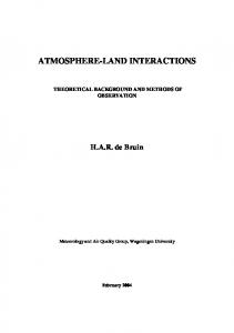
Exercise 7 Consider the active suspension system of a transport vehicle as depicted in Figure 1.2. The system is modeled by the equations m2 q¨2 + b2 (q˙2 − q˙1 ) + k2 (q2 − q1 ) − F = 0 m1 q¨1 + b2 (q˙1 − q˙2 ) + k2 (q1 − q2 ) + k1 (q1 − q0 ) + F = 0 where F (resp. −F ) is a force acting on the chassis mass m2 (the axle mass m1 ). Here, q2 − q1 is the distance between chassis and axle, and q¨2 denotes the acceleration of the chassis mass m2 . b2 is a damping coefficient and k1 and k2 are spring coefficients. The variable q0 represents the road profile. A ‘real life’ set of system parameters is given in Table 1.1.
1.7. EXERCISES
35
m1 1.5 × 10³
m2 1.0 × 10⁴
k1 5.0 × 10⁶
k2 5.0 × 10⁵
b2 50 × 103
Table 1.1: Physical parameters
1. Consider the case where F = 0 and q0 = 0 (thus no active force between chassis and axle and ‘flat’ road characteristic) and compute the eigenmodes of this autonomous system. 2. Determine a Lyapunov function V (q1 , q2 , q˙1 , q˙2 ) of this system (with F = 0 and q0 = 0) and show that its derivative is negative along solutions of the autonomous behavior of the system (i.e. F = 0 and q0 = 0). 3. Design your favorite road profile q0 in Matlab and simulate the response of the system to this road profile (the force F is kept 0). Plot the variables q1 and q2 . What are your conclusions? 4. Depending on the load of the truck, the chassis mass m2 is a major source of uncertainty. Simulate the response of the system to the road profile q0 when the mass m2 varies between its minimum value m2,min = 1.5 × 10³ (unloaded) and its maximum value m2,max = 1.0 × 10⁴ (fully loaded). Moreover, it is reasonable to assume that the air spring stiffness k2 is influenced by the load according to k2 =
m2 × k2,max m2,max
where k2,max = 5.0 × 10⁵ . Introduce an arbitrary, non-constant function m2 (t) reflecting the time-varying changes in the chassis mass m2 and let the air spring stiffness k2 depend on m2 as above. Use the routines introduced in Subsection 1.5.4 for a time simulation of this situation and plot the variables q1 and q2 .
36
Convex optimization and linear matrix inequalities
Figure 1.1: Aleksandr Mikhailovich Lyapunov
1.7. EXERCISES
37
m2 b2
6q2
6 k2 F ? m1
6q1
k1 r
6q0
Figure 1.2: Model for suspension system
38
Convex optimization and linear matrix inequalities
Chapter 2
Dissipativity and robustness analysis 2.1 2.1.1
Dissipative dynamical systems and LMI’s Introduction
The notion of dissipativity is a most important concept in systems theory both for theoretical considerations as well as from a practical point of view. Especially in the physical sciences, dissipativity is closely related to the notion of energy. Roughly speaking, a dissipative system is characterized by the property that at any time the amount of energy which the system can conceivably supply to its environment can not exceed the amount of energy that has been supplied to it. Stated otherwise, when time evolves a dissipative system absorbs a fraction of its supplied energy and transforms it for example into heat, an increase of entropy, mass, electromagnetic radiation, or other kinds of energy ‘losses’. In many applications, the question whether a system is dissipative or not can be answered from physical considerations on the way the system interacts with its environment. For example, by observing that the system is an interconnection of dissipative components, or by considering systems in which a loss of energy is inherent to the behavior of the system (due to friction, optical dispersion, evaporation losses, etc.). In this section we will formalize the notion of a dissipative dynamical system for a very general class of systems. It will be shown that linear matrix inequalities occur in a very natural way in the study of linear dissipative systems. Perhaps the most appealing framework for studying LMI’s in system and control theory is within the framework of dissipative dynamical systems. It will be shown that solutions of LMI’s have a natural interpretation as storage functions associated with a dissipative system. This interpretation will play a key role in understanding the importance of LMI’s in questions related to stability, robustness, and H∞ and H2 controller design problems. More details on the theory of this section can be found in [45, 47, 48]. 39
40
2.1.2
Dissipativity and robustness analysis
Dissipativity
Consider a continuous time, time-invariant dynamical system � described by the equations x˙ = f (x, u) y = g(x, u)
(2.1.1a) (2.1.1b)
Here, x is the state which takes its values in a state space X, u is the input taking its values in an input space U and y denotes the output of the system which assumes its values in the output space Y . Throughout this section, the precise representation of the systems will not be relevant. What we need, though, is that for any initial condition x(0) = x0 of (2.1.1a) and for any input u belonging to an input class U, the state x and the output y are uniquely defined and depend on u in a causal way. The system (2.1.1) therefore generates outputs from inputs and initial conditions. Let s :U ×Y →R be a mapping and assume that for all t0 , t1 ∈ R and for all input-output pairs u, y satisfying (2.1.1) the composite function # t1
s(t) := s(u(t), y(t))
is locally integrable, i.e., t0 |s(t)|dt < ∞. (We do realize that we abuse notation here). The mapping s will be referred to as the supply function. Definition 2.1 (Dissipativity) The system � with supply rate s is said to be dissipative if there exists a non-negative function V : X → R such that � t1 V (x(t0 )) + s(u(t), y(t))dt � V (x(t1 )) (2.1.2) t0
for all t0 � t1 and all trajectories (u, x, y) which satisfy (2.1.1). Interpretation 2.2 The supply function (or supply rate) s should be interpreted as the supply delivered to #the system. This means that in a time interval [0, t] work has been done on the system t whenever 0 s(τ )dτ is positive, while work is done by the system if this integral is negative. The non-negative function V is called a storage function and generalizes the notion of an energy function for a dissipative system. With this interpretation, inequality (2.1.2) formalizes the intuitive idea that a dissipative system is characterized by the property that the change of internal storage V (x(t1 )) − V (x(t0 )) in any time interval [t0 , t1 ] will never exceed the amount of supply that flows into the system (or the ‘work done on the system’). This means that part of what is supplied to the system is stored, while the remaining part is dissipated. Inequality (2.1.2) is known as the dissipation inequality. Remark 2.3 Since the system communicates with its environment through the variables u and y, it is logical to assume that the supply function s is a function defined on the external signal space U × Y . Moreover, since storage is a concept related to the status of internal variables of the system, it is logical to define storage functions as state functions.
2.1. DISSIPATIVE DYNAMICAL SYSTEMS AND LMI’S
41
Remark 2.4 Note that whenever the composite function V (x(·)) with V a storage function and x : R → X a state trajectory satisfying(2.1.1a), is differentiable as a function of time, then (2.1.2) can be equivalently written as V˙ (t) � s(u(t), y(t)).
(2.1.3)
Remark 2.5 There are a few refinements to Definition 2.1 which are worth mentioning. The system � is said to be conservative (or lossless) if there exists a non-negative function V : X → R such that equality holds in (2.1.2) for all t0 � t1 and all (u, x, y) which satisfy (2.1.1). Also, Definition 2.1 can be generalized to time-varying systems by letting the supply rate s depend on time. We will not need such a generalization for our purposes. Many authors have proposed a definition of dissipativity for discrete time systems, but since we can not think of any physical example of such a system, there seems little point in doing this. Another refinement consists of the idea that a system � may be dissipative with respect to more than one supply function. See Example 2.8 below. The notion of strict dissipativity is a refinement of Definition 2.1 which we will use in the sequel. It is defined as follows. Definition 2.6 (Strict dissipativity) The system � with supply rate s is said to be strictly dissipative if there exists an � > 0 and a non-negative function V : X → R which attains a strong global minimum (see Chapter 1) such that the dissipation inequality � t1 ! V (x(t0 )) + s(u(t), y(t)) − � 2 �u(t)�2 dt � V (x(t1 )) (2.1.4) t0
holds for all t0 � t1 and all trajectories (u, x, y) which satisfy (2.1.1). Clearly, a system is strictly dissipative only if a strict inequality holds in (2.1.2). Note that storage functions of strictly dissipative systems are assumed to have a strong global minimum at some point x ∗ ∈ X. This means that for any state x in a neighborhood of x ∗ the storage V (x) is strictly larger than V (x ∗ ). Example 2.7 The classical motivation for the study of dissipativity comes from circuit theory. In the analysis of electrical networks the product of voltages and currents at the external branches of a network, i.e. the power, is an obvious supply function. Similarly, the product of forces and velocities is a candidate supply function in mechanical systems. For those familiar with the theory of bondgraphs we remark that every bond-graph can be viewed as a representation of a dissipative dynamical system where input and output variables are taken to be effort and flow variables and the supply function s is invariably taken to be the product of these two variables. A bond-graph is therefore a special case of a dissipative system (and not the other way around!). Example 2.8 Consider a thermodynamic system at uniform temperature T on which mechanical work is being done at rate W and which is being heated at rate Q. Let (T , Q, W ) be the external variables of such a system and assume that –either by physical or chemical principles or through experimentation– the mathematical model of the thermodynamic system has been decided upon and
42
Dissipativity and robustness analysis
is given by the time invariant system (2.1.1). The first and second law of thermodynamics may then be formulated in the sense of Definition 2.1 by saying that the system � is conservative with respect to the supply function s1 := (W + Q) and dissipative with respect to the supply function s2 := −Q/T . Indeed, the two basic laws of thermodynamics state that for all system trajectories (T , Q, W ) and all time instants t0 � t1 � t1 E(x(t0 )) + Q(t) + W (t) dt = E(x(t1 )) t0
(which is conservation of thermodynamical energy) and the second law of thermodynamics states that the system trajectories satisfy � t1 Q(t) S(x(t0 )) + dt � S(x(t1 )) − T (t) t0 for a storage function S. Here, E is called the internal energy and S the entropy. The first law promises that the change of internal energy is equal to the heat absorbed by the system and the mechanical work which is done on the system. The second law states that the entropy decreases at a higher rate than the quotient of absorbed heat and temperature. Note that thermodynamical systems are dissipative with respect to more than one supply function! Example 2.9 Typical examples of supply functions s : U × Y → R are s(u, y) = u� y, s(u, y) = �y�2 − �u�2 s(u, y) = �y�2 + �u�2 s(u, y) = �y�2 which arise in network theory, bondgraph theory, scattering theory, H∞ theory, game theory and LQ-optimal control and H2 -optimal control theory. If � is dissipative with storage function V then we will assume that there exists a reference point x ∗ ∈ X of minimal storage, i.e. there exists x ∗ ∈ X such that V (x ∗ ) = minx∈X V (x). Given a storage function V , its normalization (with respect to x ∗ ) is defined as V¯ (x) := V (x) − V (x ∗ ). Obviously, V¯ (x ∗ ) = 0 and V¯ is a storage function of � whenever V is. Instead of considering the set of all possible storage functions associated with a dynamical system � we will restrict attention to the set of normalized storage functions. Formally, the set of normalized storage functions (associated with (�, s)) is defined by V(x ∗ ) := {V : X → R+ | V (x ∗ ) = 0 and (2.1.2) holds}. The existence of a reference point x ∗ of minimal storage implies that for a dissipative system � t1 s(u(t), y(t)) dt � 0 0
2.1. DISSIPATIVE DYNAMICAL SYSTEMS AND LMI’S
43
for any t1 � 0 and any (u, x, y) satisfying (2.1.1) with x(0) = x ∗ . Stated otherwise, any trajectory of the system which emanates from x ∗ has the property that the net flow of supply is into the system. In many treatments of dissipativity this property is often taken as definition of passivity. We introduce two mappings Vav : X → R+ ∪ ∞ and Vreq : X → R ∪ {−∞} which will play a crucial role in the sequel. They are defined by % $ � t1 (2.1.5a) s(t) dt | t1 � 0; (u, x, y) satisfy (2.1.1) with x(0) = x0 Vav (x0 ) := sup − � 0 Vreq (x0 ) := inf
0
t−1
s(t) dt | t−1 � 0; (u, x, y) satisfy (2.1.1) with
x(0) = x0 and x(t−1 ) = x ∗
(2.1.5b)
&
Then Vav (x) denotes the maximal amount of internal storage that may be recovered from the system over all state trajectories starting from x. Similarly, Vreq (x) reflects the minimal supply the environment has to deliver to the system in order to excite the state x via any trajectory in the state space originating in x ∗ . We refer to Vav and Vreq as the available storage and the required supply, respectively. Note that in (2.1.5b) it is assumed that the point x0 ∈ X is reachable from the reference pont x ∗ , i.e. it is assumed that there exist a control input u which brings the state trajectory x from x ∗ at time t = t−1 to x0 at time t = 0. This is the case when the system � is controllable. Proposition 2.10 (Willems) Let the system � be described by (2.1.1) and let s be a supply function. Then 1. � is dissipative if and only if Vav (x) is finite for all x ∈ X. 2. If � is dissipative and controllable then (a) Vav , Vreq ∈ V(x ∗ ). (b) {V ∈ V(x ∗ )} ⇒ {For all x ∈ X there holds 0 � Vav (x) � V (x) � Vreq (x)}. (c) V(x ∗ ) is a convex set. In particular, Vα := αVav +(1−α)Vreq ∈ V(x ∗ ) for all α ∈ (0, 1). Interpretation 2.11 Proposition 2.10 gives a necessary and sufficient condition for a system to be dissipative. It shows that both the available storage and the required supply are possible storage functions. Moreover, statement (b) shows that the available storage and the required supply are the extremal storage functions in V(x ∗ ). In particular, for any state of a dissipative system, the available storage is at most equal to the required supply. In addition, convex combinations of the available storage and the required supply are candidate storage functions for a dissipative system. Proof. 1. Let � be dissipative, V a storage function and x0 ∈ X. From (2.1.2) it then follows that for all t1 � 0 and all (u, x, y) satisfing (2.1.1) with x(0) = x0 , � t1 s(u(t), y(t))dt � V (x0 ) < ∞. − 0
44
Dissipativity and robustness analysis
Taking the supremum over all t1 � 0 and all such trajectories (u, x, y) (with x(0) = x0 ) yields that Vav (x0 ) � V (x0 ) < ∞. To prove the converse implication it suffices to show that Vav is a storage function. To see this, first note that Vav (x) � 0 for all x ∈ X (take t1 = 0 in (2.1.5a)). To prove that Vav satisfies (2.1.2), let t0 � t1 � t2 and (u, x, y) satisfy (2.1.1). Then � t1 � t2 s(u(t), y(t))dt − s(u(t), y(t))dt. Vav (x(t0 )) � − t0
t1
Since the second term in the right hand side of this inequality holds for arbitrary t2 � t1 and arbitrary (u, x, y)|[t1 ,t2 ] (with x(t1 ) fixed), we can take the supremum over all such trajectories to conclude that � t1 s(u(t), y(t))dt − Vav (x(t1 )). Vav (x(t0 )) � − t0
which shows that Vav satisfies (2.1.2). 2a. Suppose that � is dissipative and let V be a storage function. Then V¯ (x) := V (x) − V (x ∗ ) ∈ V(x ∗ ) so that V(x ∗ ) = ∅. Observe that Vav (x ∗ ) � 0 and Vreq (x ∗ ) � 0 (take t1 = t−1 = 0 in (2.1.5)). Suppose that the latter inequalities are strict. Then, using controllability of the system, there exists #t t−1 � 0 � t1 and a state trajectory x with x(t−1 ) = x(0) = x(t1 ) = x ∗ such that − 01 s(t)dt > 0 and # t1 #0 #0 t−1 s(t)dt < 0. But this yields a contradiction with (2.1.2) as both 0 s(t)dt � 0 and t−1 s(t)dt � 0. Thus, Vav (x ∗ ) = Vreq (x ∗ ) = 0. We already proved that Vav is a storage function so that Vav ∈ V(x ∗ ). Along the same lines one shows that also Vreq ∈ V(x ∗ ). 2b. If V ∈ V(x ∗ ) then
� −
t1
� s(u(t), y(t))dt � V (x0 ) �
0
0
s(u(t), y(t))dt t−1
for all t−1 � 0 � t1 and (u, x, y) satisfying (2.1.1) with x(t−1 ) = x ∗ and x(0) = x0 . Now take the supremum and infimum over all such trajectories to obtain that Vav � V � Vreq . 2c. Follows trivially from (2.1.2). If the system � is dissipative with respect to the supply function s then � t1 s(u(t), y(t)) dt − V (x(t1 )) V (x(t0 )) + t0
is a non-negative quantity that can be interpreted as the amount of supply that is dissipated in the system in the time interval [t0 , t1 ]. Definition 2.12 (Dissipation functions) A function d : X × U → R is called a dissipation function for (�, s) if there exists a storage function V : X → R+ such that � t1 [s(u(t), y(t)) − d(x(t), u(t))] dt = V (x(t1 )) V (x(t0 )) + t0
hold for all t0 � t1 and all trajectories (u, x, y) which satisfy (2.1.1).
2.2. LINEAR DISSIPATIVE SYSTEMS WITH QUADRATIC SUPPLY RATES
45
Obviously, the system � is dissipative with respect to the supply function s if and only if the dissipation function d is non-negative in the sense that d(x, u) � 0 for all x, u. Note that if d is a dissipation function then the system is conservative with respect to the supply function s − d.
2.1.3
Storage functions and Lyapunov functions
Storage functions and Lyapunov functions (introduced in the previous chapter) are closely related. Indeed, if u(t) = u∗ with u∗ ∈ U is taken as a constant input in (2.1.1) then we obtain the autonomous system x˙ = f (x, u∗ ) y = g(x, u∗ ). Let x ∗ be an equilibrium point of this system and suppose that the system defined by (2.1.1) is dissipative with supply s(u∗ , y) = s(u∗ , g(x, u∗ )) � 0 for all x in a neigborhood of x ∗ . From Remark 2.4 we then infer that any (differentiable) storage function V of this system is non-negative and monotone non-increasing along solutions in a neighborhood of x ∗ . Consequently, by Lyapunov’s theorem, x ∗ is a stable equilibrium if the storage function V attains a strong local minimum at x ∗ . In that case, the storage function V is nothing else than a Lyapunov function defined in a neighborhood of x ∗ . (See the corresponding definitions in the previous chapter).
2.2
Linear dissipative systems with quadratic supply rates
In this section we will apply the above theory of dissipative dynamical systems to linear input-output systems � described by the equations x˙ = Ax + Bu y = Cx + Du
(2.2.1)
with state space X = Rn , input space U = Rm and output space Y = Rp . Consider a general quadratic supply function s : U × Y → R defined by � �� � �� � y Qyy Qyu y s(u, y) = u u Quy Quu Here,
� � Qyy Qyu Q := Quy Quu
(2.2.2)
46
Dissipativity and robustness analysis
is a real symmetric matrix which is partitioned conformally with u and y. We emphasize that no a priori definiteness assumptions are made on Q. Note that the supply functions given in Example 2.9 can all be written in the form (2.2.2) for an appropriate partitioned real symmetric matrix Q. Remark 2.13 Substituting the output equation y = Cx + Du in the supply function (2.2.2) shows that (2.2.2) can equivalently be viewed as a quadratic function in the variables u and x. Indeed, �� � � �� � Qxx Qxu x x s(u, y) = s(u, Cx + Du) = u Qux Quu u where �
Qxx Qxu Qux Quu
� =
� �� � �� � C D Qyy Qyu C D . 0 I 0 I Quy Quu
The following proposition is the main result of this section. It provides necessary and sufficient conditions for dissipativeness of the pair (�, s) and it shows that linear dissipative systems with quadratic supply functions have at least one quadratic storage function. Proposition 2.14 Suppose that the system � described by (2.2.1) is controllable and let the supply function s be defined by (2.2.2). Then the following statements are equivalent. 1. (�, s) is dissipative. 2. (�, s) admits a quadratic storage function V (x) := x � Kx with K = K � � 0. 3. There exists K = K � � 0 such that � � �� � � � �� � A K + KA KB Qyy Qyu C D C D F (K) := − � 0. + Quy Quu 0 I 0 I B �K 0
(2.2.3)
� � 0 such that V (x) = x � K x. 4. There exists K− = K− av − � � 0 such that V (x) = x � K x. 5. There exists K+ = K+ req +
Moreover, if one of the above equivalent statements holds, then V (x) := x � Kx is a quadratic storage function in V(0) if and only if K � 0 and F (K) � 0. Proof. (1⇒2,4). If (�, s) is dissipative then we infer from Proposition 2.10 that the available storage Vav (x) is finite for any x ∈ Rn . We claim that Vav (x) is a quadratic function of x. This follows from [46] upon noting that the supply function s is quadratic and that � t1 � t1 Vav (x) = sup − s(t)dt = − inf s(t)dt 0
0
2.2. LINEAR DISSIPATIVE SYSTEMS WITH QUADRATIC SUPPLY RATES
47
denotes the optimal cost of a linear quadratic optimization problem. It is well known that this infimum is a quadratic form in x. (4⇒1). Obvious from Proposition (2.10). (2⇒3). If V (x) = x � Kx with K � 0 is a storage function then the dissipation inequality can be rewritten as � � t1 � d � − x(t) Kx(t) + s(u(t), y(t)) dt � 0. dt t0 Substituting the system equations (2.2.1), this is equivalent to �� � � �� �� � � � �� � � t1 � x(t) Qyy Qyu C D x(t) A K + KA KB C D dt � 0. − + u(t) 0 I u(t) Quy Quu 0 I B �K 0 t0
�� � F (K)
(2.2.4) Since (2.2.4) holds for all t0 � t1 and all inputs u this reduces to the requirement that K � 0 satisfies the LMI F (K) � 0. (3⇒2). Conversely, if there exist K � 0 such that F (K) � 0 then (2.2.4) holds and it follows that V (x) = x � Kx is a storage function which satisfies the dissipation inequality. (1⇔5). If (�, s) is dissipative then by Proposition (2.10), Vreq is a storage function. Since Vreq is defined as an optimal cost corresponding to a linear quadratic optimization problem, Vreq is quadratic. Hence, if the reference point x ∗ = 0, Vreq (x) is of the form x � K+ x for some K+ � 0. Conversely, if Vreq = x � K+ x, K+ � 0, then it is easily seen that Vreq satisfies the dissipation inequality (2.1.2) which implies that (�, s) is dissipative. We recognize in (2.2.3) a non-strict linear matrix inequality. The matrix F (K) is usually called the dissipation matrix. Observe that in the above proposition the set of quadratic storage functions in V(0) is completely characterized by the inequalities K � 0 and F (K) � 0. In other words, the set of normalized quadratic storage functions associated with (�, s) coincides with the feasibility set of the system of LMI’s K = K � � 0 and F (K) � 0. In particular, the available storage and the required supply are quadratic storage functions and hence K− and K+ also satisfy F (K− ) � 0 and F (K+ ) � 0. Using Proposition 2.10 it moreover follows that any solution K = K � � 0 of F (K) � 0 has the property that 0 � K− � K � K+ . In other words, among the set of positive semi-definite solutions K of the LMI F (K) � 0 there exists a smallest and a largest element. For conservative and strictly dissipative systems with quadratic supply functions a similar characterization can be given. The precize formulation for conservative systems is evident from Proposition 2.14 and is left to the reader. For strictly dissipative system the result is worth mentioning.
48
Dissipativity and robustness analysis
Proposition 2.15 Suppose that the system � described by (2.2.1) is controllable and let the supply function s be defined by (2.2.2). Then the following statements are equivalent. 1. (�, s) is strictly dissipative. 2. There exists K = K � > 0 such that � � �� � � � �� � A K + KA KB Qyy Qyu C D C D F (K) := − > 0 + Quy Quu 0 I 0 I B �K 0
(2.2.5)
Moreover, if one of the above equivalent statements holds, then V (x) := x � Kx is a quadratic storage function in V(0) if and only if K > 0 and F (K) > 0. Proof. The proof proceeds along the same lines as the proof of Proposition 2.14. We only prove the implication (2⇒1) here. Let K > 0 be such that F (K) > 0. Then obviously, there exists � > 0 such that � � 0 0 F (K) − � 0. 0 �2I But then � t1 � t0
��
x(t) u(t)
�� � � �� � � t1 � � t1 0 0 x(t) x(t) x(t) dt � � 2 |u(t)|2 dt dt = u(t) u(t) u(t) 0 �2I t0 t0
� F (K)
from which it follows that V (x) = x � Kx is a storage function with a strong global minimum at x = 0 which satisfies the dissipation inequality (2.1.4). Hence, the pair (�, s) is strictly dissipative.
There is a simple relation between the dissipation matrix F (K) and dissipation functions. Indeed, if K = K � � 0 (or > 0) is such that F (K) � 0 then the dissipation matrix can be factorized as � �� � � MK N K . F (K) = MK NK � � where MK NK is a real matrix with n + m columns and r � rK := rank(F (K)) rows. For any triple (u, x, y) satisfying (2.2.1) we then obtain that �
t1
� �MK x(t) + NK u(t)�2 dt =
t0
t1
t0
� �� � � x x F (K) dt u u �
�
= x(t0 ) Kx(t0 ) − x(t1 ) Kx(t1 ) +
�
t1
s(t) dt. t0
In other words the function d(x, u) := �MK x + NK u�2
2.2. LINEAR DISSIPATIVE SYSTEMS WITH QUADRATIC SUPPLY RATES
49
is a dissipation function of the system (2.2.1). We conclude this subsection with a frequency domain characterization of dissipativeness. Let G(s) := C(I s − A)−1 B + D denote the transfer function associated with (2.2.1). Proposition 2.16 (Yakubovich-Kalman) Under the same conditions as Proposition 2.14, the following statements are equivalent. 1. (�, s) is dissipative. 2. For all ω ∈ R with det(iωI − A) = 0, there holds � �∗ � �� � G(iω) Qyy Qyu G(iω) � 0 I Quy Quu I
(2.2.6)
Proof. Because of the simplicity of the argument, we only prove the implication (1⇒2) here. Let ω ∈ R be such that det(iωI − A) = 0 and consider the (complex) input u(t) = exp(iωt)u0 with u0 ∈ Rm . Define x(t) := exp(iωt)(iωI − A)−1 Bu0 and y(t) := Cx(t) + Du(t). Then y(t) = exp(iωt)G(iω)u0 and the triple (u, x, y) satisfies (2.2.1). Moreover, � �∗ � �� � Qyy Qyu G(iω) ∗ G(iω) s(u(t), y(t)) = u¯ 0 u0 I I Quy Quu which is a constant for all time t ∈ R. Now suppose that (�, s) is dissipative. For non-zero frequencies ω the triple (u, x, y) is periodic with period P = 2π/ω. In particular, there must exist a time instant t0 such that x(t0 ) = x(t0 + kP ) = 0, k ∈ Z. Since V (0) = 0, the dissipation inequality (2.1.2) reads �∗ � �� � � t1 � t1 � Qyy Qyu G(iω) ∗ G(iω) u0 s(u(t), y(t)) dt = u¯ 0 I I Quy Quu t0 t0 � �∗ � �� � Qyy Qyu G(iω) ∗ G(iω) u0 � 0 = (t1 − t0 )u¯ 0 Quy Quu I I for all t1 > t0 . Since u0 and t1 > t0 are arbitrary this yields that statement 2 holds. The converse implication is much more involved and will be omitted here. The frequency domain characterization of strictly dissipative systems is similar and involves a strict inequality in (2.2.6). Proposition 2.16 has a long history in system theory. The result goes back to V.A. Yakubovich (1962) and R. Kalman (1963).
2.2.1
The positive real lemma
Consider the system (2.2.1) together with the quadratic supply function s(u, y) = y � u as defined in 2.2.2. The following is then an immediate consequence of Proposition 2.14.
50
Dissipativity and robustness analysis
Corollary 2.17 Suppose that the system � described by (2.2.1) is controllable and has transfer function G. Let s(u, y) = y � u be a supply function. Then equivalent statements are 1. (�, s) is dissipative. 2. the system of LMI’s K = K� � 0 � � −A� K − KA −KB + C � � 0 −B � K + C D + D� is feasible 3. For all ω ∈ R with det(iωI − A) = 0 G(iω)∗ + G(iω) � 0. Moreover, V (x) = x � Kx defines a quadratic storage function if and only if K satisfies the above system of LMI’s. Remark 2.18 Corollary 2.17 is known as the Kalman-Yacubovich-Popov or the positive real lemma and has played a crucial role in questions related to the stability of control systems and synthesis of passive electrical networks. Transfer functions which satisfy the third statement are generally called positive real.
2.2.2
The bounded real lemma
Consider the quadratic supply function s(u, y) = γ 2 u� u − y � y
(2.2.7)
where γ � 0. In a similar fashion we obtain the following result as an immediate consequence of Proposition 2.14. Corollary 2.19 Suppose that the system � described by (2.2.1) is controllable and has transfer function G. Let s(u, y) = γ 2 u� u − y � y be a supply function. Then equivalent statements are 1. (�, s) is dissipative. 2. The system of LMI’s K = K� � 0 � � � A K + KA + C � C KB + C � D � 0 D�D − γ 2 I B �K + D�C is feasible.
2.3. NOMINAL PERFORMANCE AND LMI’S
51
3. For all ω ∈ R with det(iωI − A) = 0 G(iω)∗ G(iω) � γ 2 I . Moreover, V (x) = x � Kx defines a quadratic storage function if and only if K satisfies the above system of LMI’s. Let us analyze the importance of this result for control. If � is dissipative with respect to the supply function (2.2.7) then we infer from Remark 2.4 that for any quadratic storage function V (x) = x � Kx, V˙ � γ 2 u� u − y � y
(2.2.8)
along solutions (u, x, y) of (2.2.1). Suppose that x(0) = 0, A has all its eigenvalues in the open left-half complex plane and the input u is taken from the set L2 of square integrable functions, i.e., u is such that � ∞ 2 u� (t)u(t) dt < ∞. �u�2 := 0
Then both the state x and the output y of (2.2.1) are square integrable functions and limt→∞ x(t) = 0. We can therefore integrate (2.2.8) from t = 0 till ∞ to obtain that for all u ∈ L2 γ 2 �u�22 − �y�22 � 0. Equivalently, sup u∈L2
�y�2 � γ. �u�2
(2.2.9)
The left-hand side of (2.2.9) is the so called L2 -induced norm or L2 -gain of the system (2.2.1). The L2 -gain is therefore obtained as the smallest γ � 0 for which (2.2.9) holds. Translated in terms of LMI’s, we therefore obtain that the upperbound (2.2.9) holds if and only if there exists K that satisfies the linear matrix inequalities of Corollary (2.19). This provides a feasibility test, parametrized in γ > 0, to determine L2 -gain of the system.
2.3
Nominal performance and LMI’s
In this section we will use the previous results on dissipative systems to characterize a number of relevant performance criteria for dynamical systems. In view of forthcoming chapters we consider the system (2.2.1) and assume throughout this section that the system is asymptotically stable (i.e. the eigenvalues of A are in the open left-half complex plane). The following lemma is a simple but useful variation on one of the implications of Proposition 2.15. Lemma 2.20 Consider the following statements.
52
Dissipativity and robustness analysis
1. (�, s) is strictly dissipative 2. There exists K = K � > 0 such that F (K) > 0 3. There exists � > 0 such that �� � �� � � ∞ � ∞� y(t) Qyy Qyu y(t) dt � � u(t)� u(t)dt − x(0)� Kx(0). u(t) u(t) Quy Quu 0 0
(2.3.1)
Then statements 1. and 2. are equivalent and each of these statements implies 3. Proof. If K = K � > 0 is such that K(K) > 0 then we can choose � > 0 such that � � 0 0 G(K) := F (K) − � 0. 0 �2I Viewing this as a dissipation inequality for a dissipative system yields that for all u ∈ L2 �� � � � ∞� x(t) x(t) G(K) dt u(t) u(t) 0 � � ∞ � d − x(t)� Kx(t) − � 2 u(t)� u(t) + s(u(t), y(t)) dt dt 0 where s(u, y) is the quadratic supply function given in (2.2.2). Stability of the system yields that for all u ∈ L2 the state x(t) vanishes for t → ∞. The inequality (2.3.1) then follows.
2.3.1
H∞ nominal performance
A popular performance measure of a stable linear time-invariant system is the H∞ norm of its transfer function. It is defined as follows. The transfer function associated with (2.2.1) is defined by G(s) := C(I s − A)−1 B + D where s ∈ C. Since the system is assumed to be stable, G(s) is bounded for all s ∈ C with positive real part. By this, we mean that the largest singular value σmax (G(s)) is finite for all s ∈ C with �s > 0. The space H∞ consists of all complex valued functions which are analytic in �s > 0 and for which �G�∞ := sup σmax (G(s)) < ∞. �s>0
The left hand side of this expression satisfies the axioms of a norm and defines the H∞ norm of G. It can be shown that each function in H∞ has a unique extension to the imaginary axis and that in fact the H∞ norm is given by �G�∞ = sup σmax (G(j ω)). ω∈R
2.3. NOMINAL PERFORMANCE AND LMI’S
53
In words, the H∞ norm of a transfer function is the supremum of the maximum singular value of the frequency response of the system. Remark 2.21 Various graphical representations of frequency responses are illustrative to investigate system properties like bandwidth, gains, etc. Probably the most important one is a plot of the singular values σi (G(j ω)) (i = 1, . . . , min(m, p)) viewed as function of frequency ω ∈ R. For single-input single-output systems there is only one singular value and σ (G(j ω)) = |G(j ω)|. A Bode diagram is a plot of the latter and provides information to what extent the system amplifies purely harmonic input signals with frequencies ω ∈ R. In order to interpret these diagrams one usually takes logarithmic scales on the ω axis and plots 2010 log(G(j ω)) to get units in dB. The H∞ norm of a transfer function is then nothing else than the highest peak value occuring in the Bode plot. The connection between time-domain and frequency-domain norms is most clearly expressed in the following standard result. Proposition 2.22 Let G ∈ H∞ be the transfer function of the asymptotically stable system (2.2.1). Then for all initial conditions x(0) = x0 , u ∈ L2 implies y ∈ L2 and with x(0) = 0 there holds that �G�∞ = sup
u∈L2
�y�2 . �u�2
Interpretation 2.23 For a stable system, the H∞ norm of its transfer function is the L2 -induced norm of the input-output operator associated with the system. This yields a simple relation between the Bounded Real Lemma, Lemma 2.20 and bounds on the H∞ norm of transfer functions: Proposition 2.24 If the system (2.2.1) is asymptotically stable then �G�∞ < γ whenever there exists a solution K = K � > 0 to the LMI � � � A K + KA + C � C KB + C � D < 0. (2.3.2) D�D − γ 2 I B �K + D�C Proof. Apply Lemma 2.20 with x0 = 0, Qyy = I , Qyu = 0, Quy = 0 and Quu = −γ 2 I to infer that the existence of a solution K > 0 to the LMI implies that for all u ∈ L2 � ∞ � ∞ �y�22 = y(t)� y(t)dt � (γ 2 − �) u(t)� u(t)dt 0 0 � ∞ < γ2 u(t)� u(t)dt = γ 2 �u�22 . 0
Proposition 2.22 then yields that �G�∞ < γ as desired. Interpretation 2.25 We can compute the smallest possible upperbound of the L2 -induced gain of the system (which is the H∞ norm of the transfer function) by minimizing γ > 0 over all variables γ and K > 0 that satisfy the LMI (2.3.2).
54
2.3.2
Dissipativity and robustness analysis
H2 nominal performance
Consider the system (2.2.1) and suppose that we are interested only in the impulse responses of this system. This means, that we take impulsive inputs1 of the form u(t) = δ(t)ei with ei the i − th basis vector in the standard basis of the input space Rm . (i runs from 1 till m). With zero initial conditions, the corresponding output y i belongs to L2 and is given by ⎧ ⎪ ⎨C exp(At)Bei for t > 0 i y (t) = Dei δ(t) for t = 0 . ⎪ ⎩ 0 for t < 0 Only if D = 0, the sum of the squared norms of all such impulse responses is well defined and given by m �
� �y i �22
= trace
∞
B � exp(A� t)C � C exp(At)B dt
0
i=1
� = trace
∞
C exp(At)BB � exp(A� t)C � dt
0
Long ago, Parseval taught us that the latter is equal to � ∞ 1 G(j ω)G(j ω)∗ dω trace 2π −∞
(2.3.3)
where G is the transfer function of the system. The square root of this expression satisfies the axioms of a norm of the transfer function G and we will refer to the square root of (2.3.3) as the H2 norm of G. Precisely, H2 is the class of complex valued functions which are analytic at �s > 0 and for which ' � ∞ 1 �G�2 := G(σ + j ω)[G(σ + j ω)]∗ dω sup trace 2π σ >0 −∞ is finite. This defines the H2 norm of G. As in H∞ , it can be shown that each function in H2 has a unique extension to the imaginary axis and that in fact the H2 norm is given by the square root of (2.3.3). We have the following characterization of the H2 norm a transfer function. Proposition 2.26 Suppose that the system (2.2.1) is asymptotically stable and let G(s) = C(I s − A)−1 B + D denote its transfer function. Then 1 Formally, the impulse δ is not a function and for this reason it is neither a signal. It requires a complete introduction to distribution theory to make these statements more precise, but we will not do this at this place.
2.3. NOMINAL PERFORMANCE AND LMI’S
55
1. �G�2 < ∞ if and only if D = 0. 2. The following statements are equivalent (a) �G�2 < γ (b) there exists K = K � > 0 and Z such that �
A� K + KA KB B �K −I
�
�
K C� C Z
< 0;
� > 0;
trace(Z) < γ 2
(2.3.4)
> 0;
trace(Z) < γ 2 .
(2.3.5)
(c) there exists K = K � > 0 and Z such that �
AK + KA� KC � CK −I
�
�
K B B� Z
< 0;
�
Proof. The first claim is immediate from the definition of the H2 norm. To prove the second part, note that �G�2 < γ is equivalent to requiring that the controllability gramian �
∞
W :=
exp(At)BB � exp(A� t) dt
0
satisfies trace(CW C � ) < γ 2 . Since the controllability gramian is the unique positive definite solution to the Lyapunov equation AW +W A� +BB � = 0 this is equivalent to saying that there exists X > 0 such that AX + XA� + BB � < 0;
trace(CXC � ) < γ 2 .
With a change of variables K := X−1 , this is equivalent to the existence of K > 0 and Z such that A� K + KA + KBB � K < 0;
CK −1 C � < Z;
trace(Z) < γ 2 .
Now, using Schur complements for the first two inequalities yields that �G�2 < γ is equivalent to the existence of K > 0 and Z such that � � � � � A K + KA KB K C� > 0; trace(Z) < γ 2 < 0; C Z B �K −I which is (2.3.4) as desired. The equivalence with (2.3.5) is obtained by a direct dualization and the observation that �G�2 = �G� �2 .
Interpretation 2.27 The smallest possible upperbound of the H2 -norm of the transfer function can be calculated by minimizing the criterion trace(Z) over the variables K > 0 and Z that satisfy the LMI’s defined by the first two inequalities in (2.3.4) or (2.3.5).
56
2.3.3
Dissipativity and robustness analysis
Generalized H2 nominal performance
Consider again the system (2.2.1) and suppose that D = 0. Assuming that the system is stable, any input u ∈ L2 yields an output y which has finite infinity (or amplitude) norm �y�∞ := max sup �yi (t)�. i=1,... ,p t �0
For fixed initial condition x(0) = 0 this system defines a mapping from inputs u ∈ L2 to outputs y ∈ L∞ and we will be interested in the induced (or ‘energy to peak’ or ‘generalized H2 ’ ) norm sup u∈L2
�y�∞ . �u�2
The following result characterizes an upperbound on this quantity. Proposition 2.28 Suppose that the system (2.2.1) is asymptotically stable and D = 0. Then the L2 L∞ induced norm (or generalized H2 norm) is smaller than γ if and only if there exists a solution K = K � > 0 to the LMI’s � � � � � K C� A K + KA KB >0 (2.3.6) < 0; B �K −I C γ 2I Proof. Firstly, infer from Proposition 2.14 that the existence of K > 0 with � � � A K + KA KB 0 C γ 2I is equivalent to the existence of an � > 0 such that C � C < (γ 2 − � 2 )K. Together, this yields that for all t � 0 � t � � � � 2 2 y(t) y(t) = x(t) C Cx(t) � (γ − �)x(t) Kx(t) � (γ − � ) u(τ )� u(τ ) dτ. 0
Taking the supremum over t � 0 yields the existence of � > 0 such that for all u ∈ L2 �z�2∞ � (γ 2 − � 2 )�u�22 . Dividing by �u�22 and taking the supremum over all u ∈ L2 then yields the result. Interpretation 2.29 The smallest possible upperbound of the L2 -L∞ gain of a system can be calculated by minimizing γ over all variables γ and K > 0 for which the LMI’s (2.3.6) are feasible.
2.3. NOMINAL PERFORMANCE AND LMI’S
2.3.4
57
L1 or peak-to-peak nominal performance
Consider the system (2.2.1) and assume again that the system is stable. For fixed initial condition x(0) = 0 this system defines a mapping from bounded amplitude inputs u ∈ L∞ to bounded amplitude outputs y ∈ L∞ and a relevant performance criterion is the ‘peak-to-peak’ or L∞ -induced norm of this mapping sup u∈L∞
�y�∞ . �u�∞
We just remark that this induced norm is equal to the L1 norm of the impulse response of the system. The following result gives a sufficient condition for an upperbound γ of the peak-to-peak gain of the system. Proposition 2.30 If there exists K > 0, λ > 0 and μ > 0 such that ⎞ ⎛ � � � λK 0 C� A K + KA + λK KB ⎝ 0 (γ − μ)I D � ⎠ > 0 < 0; B �K −μI C D γI
(2.3.7)
then the peak-to-peak (or L∞ induced) norm of the system is smaller than γ . Proof. The first inequality in (2.3.7) implies that d x(t)� Kx(t) + λx(t)Kx(t) − μu(t)� u(t) < 0. dt for all u and x for which x˙ = Ax + Bu. Now assume that x(0) = 0 and u ∈ L∞ with �u�∞ � 1. Then, since K > 0 we obtain (pointwise in t � 0) that x(t)� Kx(t) �
μ . λ
Taking a Schur complement of the second inequality in (2.3.7) yields that � � � �� � � 1 λK 0 C C D > 0 − 0 (γ − μ)I γ − � D� so that, pointwise in t � 0 and for all �u�∞ � 1 we can write y(t)� y(t) � (γ − �)[λx(t)� Kx(t) + (γ − μ)u(t)� u(t)] � γ (γ − �) Consequently, the peak-to-peak gain of the system is smaller than γ . Remark 2.31 We emphasize that Proposition 2.30 gives only a sufficient condition for an upperbound γ of the peak-to-peak gain of the system. The minimal γ � 0 for which the there exist K > 0, λ > 0 and μ � 0 such that (2.3.7) is satisfied is usually only an upperbound of the real peak-to-peak gain of the system.
58
Dissipativity and robustness analysis
2.4
Quadratic Lyapunov functions
An important issue in the design of control systems involves the question to what extent the stability and performance of the controlled system is robust against perturbations and uncertainties in the parameters of the system. In this section we consider the linear system defined by x˙ = A(δ)x
(2.4.1)
� � where the state matrix A(δ) is a function of a real valued parameter vector δ = δ1 , . . . , δk ∈ Rk . Let X = Rn be the state space of this system. If you like, you can think of this (autonomous) system as a feedback interconnection of a plant and a control system. We will analyze the robust stability of the equilibrium point x ∗ = 0 of this system. More precisely, we analyze to what extent the equilibrium point x ∗ = 0 is asymptotically stable when δ varies in a prescribed set, say �, of uncertain parameters. There are two particular cases of this robust stability problem that are of special interest.
1. the parameter vector δ is a fixed but unknown element of a parameter set � ⊆ Rk . 2. the parameter vector δ is a time varying function δ : R → Rk which belongs to some set � of functions in (Rk )R . The differential equation (2.4.1) is then to be interpreted as dx dt (t) = A(δ(t))x(t).
The first case typically appears in models in which the physical parameters are fixed but only approximately known up to some accuracy. Note that for these parameters (2.4.1) defines a linear time-invariant system. The second case involves time-varying uncertain parameters. For this case one can in addition distinguish between the situations where � consists of one element only (known time varying perturbations) and the situation where � is a higher dimensional set of time functions (arbitrary time varying perturbations). Robust stability against time-varying perturbations is generally a more demanding requirement for the system than robust stability against time-invariant parameter uncertainties. This, because 1 is obviously a special case of 2. We will mainly consider the general case of time-varying parametric uncertainties in the sequel.
Remark 2.32 We emphasize that in the case of constant uncertain parameters, the system x˙ = A(δ)x is asymptotically stable if and only if the eigenvalues of A(δ) lie in the open left-half complex plane for all admissible perturbations. However, we emphasize that such a test of stability does not hold for time varying systems. In particular, for time-varying perturbations it is not true that the asymptotic stability of x(t) ˙ = A(δ(t))x(t) is equivalent to the condition that the (time-varying) eigenvalues λ(A(δ(t))) belong to the stability region C− for all admissible perturbations δ(·).
2.4. QUADRATIC LYAPUNOV FUNCTIONS
2.4.1
59
Quadratic stability
A sufficient condition for x ∗ = 0 to be an asymptotically stable equilibrium point of (2.4.1) is the existence of a quadratic Lyapunov function V (x) = x � Kx with K = K � > 0 such that dV (x(t)) V˙ = �0 dt along state trajectories x of (2.4.1) that originate in a neighborhood of the equilibrium x ∗ = 0. Definition 2.33 (Quadratic stability) The system (2.4.1) is said to be quadratically stable for perturbations � if there exists a matrix K = K � > 0 such that A(δ(t))� K + KA(δ(t)) < 0 for all perturbations δ ∈ �. Interpretation 2.34 If the system (2.4.1) is quadratically stable for perturbations � then V (x) = x � Kx is a quadratic Lyapunov function for (2.4.1) for all δ ∈ �. By Proposition 1.38 the existence of a quadratic Lyapunov function implies that the equilibrium point x ∗ = 0 is asymptotically stable. Quadratic stability for perturbations � is therefore equivalent to the existence of a quadratic Lyapunov function V (x) = x � Kx, K > 0 such that dV (x(t)) = x � [A(δ(t))� K + KA(δ(t))]x < 0 dt for all δ ∈ �. Note that in general quadratic stability of the system for an uncertainty class � places an infinite number of constraints on the symmetric matrix K. It is the purpose of this section to make additional assumptions on the way the uncertainty enters the system, so as to convert the robust stability problem into a numerically tractable problem.
2.4.2
Quadratic stability of affine models
Suppose that the state matrix A(δ) is an affine function of the parameter vector δ. That is, suppose that there exist real matrices A0 , . . . Ak all of dimension n × n such that A(δ(t)) = A0 + δ1 (t)A1 + . . . + δk (t)Ak for all δ ∈ �. This is refered to as an affine parameter dependent model. Note that these do not impose restrictions on the rate of changes in the parameters, i.e., arbitrary fast time variations in the parameters are allowed.
60
Dissipativity and robustness analysis
Suppose that the uncertain parameters δj (t), j = 1, . . . , k, t ∈ R assume their values in an interval [δ j , δ¯j ], i.e., δj (t) ∈ [δ j , δ¯j ]. This means that the uncertainty of each independent parameter is assumed to be bounded between two extremal values. Define the set of corners of the uncertainty region as � � �0 := {δ = δ1 , . . . , δk | δj ∈ {δ j , δ¯j } j = 1, . . . , k} (2.4.2) and observe that this set has a finite number of elements. Proposition 2.35 If (2.4.1) is an affine parameter dependent model then it is quadratically stable if and only if there exists K = K � > 0 such that A(δ)� K + KA(δ) < 0 for all δ ∈ �0 . Proof. The proof of this result is an application of Proposition 1.19 in Chapter 1. Indeed, fix x ∈ Rn and consider the mapping fx : � → R defined by fx (δ) := x � [A(δ(t))� K + KA(δ(t))]x. The domain � of this mapping is a convex set and by definition of �0 , it is the convex hull of �0 , i.e., � = co(�0 ). Further, since A(δ) is an affine function of δ it follows that fx (δ) is a convex function of δ. In particular, Proposition 1.19 yields that fx (δ) < 0 for all δ ∈ � if and only if fx (δ) < 0 for all δ ∈ �0 . Since x is arbitrary it follows that A(δ(t))� K + KA(δ(t)) < 0,
δ∈�
A(δ(t))� K + KA(δ(t)) < 0,
δ ∈ �0
if and only if
which yields the result. Obviously, the importance of this result lies in the fact that quadratic stability can be concluded from a finite test of matrix inequalities. Note that the condition stated in Proposition 2.35 is a feasibility test of a (finite) system of LMI’s.
2.4.3
Quadratic stability of polytopic models
A second case of interest amounts to considering uncertainty defined by convex combinations of the form A(δ(t)) = α1 (t)A1 + αk (t)Ak
(2.4.3)
2.5. PARAMETER DEPENDENT LYAPUNOV FUNCTIONS
61
� where αj (t) � 0 and kj =1 αj (t) = 1 for all t ∈ R. Here, A1 , . . . , Ak are fixed real matrices of dimension n × n and the αj are to be interpreted as coefficients of a convex decomposition of the uncertain time-varying matrix A(δ(t)) over the set of vertices (A� 1 , . . . , Ak ), that is for all δ ∈ � and t ∈ R we assume the existence of coefficients αj (t) � 0 with kj =1 αj (t) = 1 such that (2.4.3) holds. We refer to such a model as a polytopic model. The state matrix of a polytopic model is therefore equivalently specified as A(δ(t)) ∈ co(A1 , . . . , Ak ) for all time-varying perturbations δ ∈ �. In particular, these polytopic models do not impose restrictions on the rate of changes in the parameters, i.e., arbitrarily fast time variations in the parameters are allowed. The main result concerning quadratic stabilization of a class of uncertain polytopic models is as follows. Proposition 2.36 If (2.4.1) is a polytopic parameter dependent model where A(δ(t)) ∈ co(A1 , . . . , Ak ) for all δ ∈ � then it is quadratically stable if and only if there exists K > I such that A� i K + KAi < 0 for all i = 1, . . . , k. Instead of proving Proposition 2.36 (See exercise 6 below) it is useful to understand the relation between Proposition 2.35 and Proposition 2.36. In fact, the class of affine models as introduced in the previous subsection can be converted to a class of polytopic models. To see this, suppose that the map A : � → Rn×n with � � (2.4.4) � := { δ1 , . . . , δk | δj ∈ [δ j , δ¯j ], j = 1, . . . , k} is affine. Let �0 be the set of corners as defined in (2.4.2). Then �0 has 2k elements and since � = co(�0 ) we have A(co(�0 )) = A(�) = {A(δ) | δ ∈ �} = co{A(δ) | δ ∈ �0 } = co(A(�0 )). The ‘corner elements’ δ ∈ �0 in the parameter space are mapped by A onto a set of vertices A(δ), δ ∈ �0 of a polytopic model. In other words, the affine model x˙ = A(δ)x with δ ∈ � = co(�0 ) can equivalently be viewed as a polytopic model where A(δ) ∈ co(A(�0 )).
2.5
Parameter dependent Lyapunov functions
The main disadvantage in searching one quadratic Lyapunov function for a class of uncertain models is the conservatism of the test to prove stability of a class of models. Indeed, the test of quadratic stability does not discriminate between systems that have slow time-varying parameters and systems whose dynamical characteristics quickly vary in time. To reduce conservatism of the quadratic stability test
62
Dissipativity and robustness analysis
we will consider quadratic Lyapunov functions for the system (2.4.1) which are parameter dependent, i.e., Lyapunov functions of the form V (x) = x � K(δ)x where the Lyapunov matrix K(δ) is allowed to dependent on the uncertain parameter δ. More specifically, we will be interested in Lyapunov functions that are affine in the parameter δ, i.e., K(δ) = K0 + δ1 K1 + . . . + δk Kk � � where K0 , . . . , Kk are real matrices of dimension n × n and δ = δ1 . . . δk . Clearly, with K1 = K2 = . . . = Kk = 0 we are back to the case of parameter independent quadratic Lyapunov functions as discussed in the previous section. Definition 2.37 (Affine quadratic stability) The system (2.4.1) is called affinely quadratically stable if there exists matrices K0 , . . . , Kk such that K(δ) := K0 + δ1 K1 + . . . δk Kk > I dK(δ) A(δ)� K(δ) + K(δ)A(δ) + 0 for all x = 0 and � � dV (x(t)) dK(δ) = x � A(δ)� K(δ) + K(δ)A(δ) x I for all δ ∈ �0
(2.5.3a) (2.5.3b)
A� i Ki
+ Ki Ai � 0 for i = 1, . . . , k (2.5.3c) �k Here, A(δ) = A0 + j =1 δj Aj and K(δ) = K0 + j =1 δj Kj . Moreover, in that case V (x, δ) := x � K(δ)x is a quadratic parameter-dependent Lyapunov function of the system. �k
Proof. It suffices to prove that (2.5.3) implies (2.5.1) for all δ ∈ �. Let x be a non-zero fixed but arbitrary element of Rn . Since K(δ) is affine in δ, the mapping δ → x � K(δ)x with δ ∈ � is convex. Consequently, x � [K(δ)−I ]x is larger than zero for all δ ∈ � if it is larger than zero for all δ ∈ �0 . As x is arbitrary, this yields that (2.5.1a) holds for all δ ∈ � whenever (2.5.3b) holds. Since for time-invariant perturbations dK(δ)/dt = 0 it now suffices to prove that (2.5.3a) and (2.5.3c) imply that (2.5.1b) holds for all δ ∈ �. This however, we showed in the arguments preceding the proposition. Interpretation 2.41 Proposition 2.40 reduces the problem to verify affine quadratic stability of the system (2.4.1) to a feasibility problem of a (finite) set of linear matrix inequalities. The latter problem is a numerically tractable one and is readily implemented in the LMI toolbox.
2.5.2
Time varying uncertainty
We conclude this section with a result on robust stability of the system (2.4.1) for time-varying parameters. Let the uncertainty set � be defined as ( � := (δ1 , . . . , δk ) | where for j = 1 . . . , k : δj : R → R is differentiable and for all t ∈ R, ) δj (t) ∈ [δ j , δ¯j ], and δ˙j (t) ∈ [λj , λ¯ j ] . (2.5.4)
2.5. PARAMETER DEPENDENT LYAPUNOV FUNCTIONS
65
This means that we assume the uncertain parameters to have bounded variation and bounded rate of variation. We further introduce the vertex sets * ) �0 := (δ1 , . . . , δk ) | δj ∈ {δ j , δ¯j } * ) �0 := (λ1 , . . . , λk ) | λj ∈ {λj , λ¯ j } . Thus �0 represents the vertices of the convex hull in which the uncertain parameters take their values, whereas �0 is a set of vertices whose convex hull represents the admissible rates of variation of the parameters. Remark 2.42 There are two extreme cases of uncertainty sets (2.5.4) worth mentioning. Firstly, if the rate of variation of the uncertain parameter δj is set to zero, δj represents a constant, time-invariant perturbation as treated in the previous section. If all perturbations are known to be time-invariant then λj = λ¯ j = 0 for j = 1, . . . , k in which case �0 becomes a singleton. Secondly, arbitrarily fast perturbations of δj are obtained by putting λj = −∞ and λ¯ j = ∞. ] The reason for considering this type of uncertainty sets lies in the fact that the last term in the left-hand side of (2.5.1b) can be evaluated exactly whenever the Lyapunov matrix K(δ) is affine in δ. Specifically, if K(δ) is affine in δ we infer that dK(δ) ˙ − K0 = δ˙1 K1 + . . . + δ˙k Kk = K(δ) dt ˙ The main result is now as follows. which is an affine function in δ. Proposition 2.43 If (2.4.1) is an affine parameter dependent model and � is the uncertainty set as defined in (2.5.4) then the system x˙ = A(δ)x, δ ∈ � is affinely quadratically stable if there exist real symmetric matrices K0 , . . . , Kk such that A(δ)� K(δ) + K(δ)A(δ) + K(λ) < K0 for all δ ∈ �0 and λ ∈ �0 K(δ) > I for all δ ∈ �0 A� i Ki
+ Ki Ai � 0 for i = 1, . . . , k
(2.5.5a) (2.5.5b) (2.5.5c)
� � Here, A(δ) = A0 + kj =1 δj Aj and K(δ) = K0 + kj =1 δj Kj . Moreover, in that case V (x, δ) := x � K(δ)x is a quadratic parameter-dependent Lyapunov function of the system. Proof. The proof of this proposition is basically a generalization of the proof of Proposition 2.40 to the time-varying case. First fix λ ∈ Rk . Then a similar argument as in the proof of Proposition 2.40 yields that (2.5.5) implies K(δ) > I �
A(δ) K(δ) + K(δ)A(δ) + K(λ) − K0 < 0
66
Dissipativity and robustness analysis
for all δ ∈ �. Since K(λ) is affine in λ and this last inequality holds for any λ ∈ �0 we conclude from the definition of � that (2.5.5) implies K(δ) > I ˙ − K0 < 0 A(δ) K(δ) + K(δ)A(δ) + K(δ) �
˙ − K0 = dK(δ)/dt to conclude that (2.5.1) holds for all δ ∈ � for all δ ∈ �. Now use that K(δ) which implies the affine quadratic stability of the system. Interpretation 2.44 Proposition 2.43 reduces the problem to verify affine quadratic stability of the system x(t) ˙ = A(δ(t))x(t) with time-varying perturbations (2.5.4) to a feasibility test of a finite set of LMI’s. Remark 2.45 It is interesting to compare the numerical complexity of the conditions of Proposition 2.40 with the conditions mentioned in Proposition 2.43. If the uncertainty vector δ is kdimensional then the vertex set �0 has dimension 2k so that the verification of conditions (2.5.3) requires a feasibility test of 2k + 2k + k linear matrix inequalities. In this case, also the vertex set �0 has dimension 2k which implies that (2.5.5) requires a feasibility test of 22k + 2k + k = 4k + 2k + k linear matrix inequalities.
2.5.3
Some software aspects
In Matlab both affine and polytopic models are implemented with the routine psys. With k = 2 the syntax is • affmodel = psys( pv, [S0, S1, S2] ) for the specification of affine models and • polmodel = psys( [S1, S2] ) for the specification of polytopic models. Here, pv is a parameter vector which is supposed to be specified by the routine pvec, i.e., pv = pvec(’box’, [ d1min d1max; d2min d2max]); which implements the ranges of the uncertain parameters. S0, S1 and S2 are system matrices which are supposed to be defined by expressions of the form
2.5. PARAMETER DEPENDENT LYAPUNOV FUNCTIONS
67
S0 = ltisys(A0, B0, C0, D0, E0); S1 = ltisys(A1, B1, C1, D1, E1); S2 = ltisys(A2, B2, C2, D2, E2); where (Ai , Bi , Ci , Di , Ei ) define the state space parameters of the model2 Ei x˙ = Ai x + Bi u;
y = Ci x + Di u.
(2.5.6)
Remark 2.46 The presence of the E matrix in the system representations of the LMI toolbox can be pretty disturbing. In particular, an affine combination of models of the form (2.5.6) with i = 0, . . . , k results in a model E x˙ = Ax + Bu;
y = Cx + Du
where E = E0 +
k �
δi E i ;
i=1
A = A0 +
k �
δi Ai ;
B = B0 +
i=1
C = C0 +
k �
k �
δi B i
i=1
δi Ci ;
D = D0 +
i=1
k �
δi D i .
i=1
If E is supposed to be independent of parameter variations then you need to explicitly set E1 = . . . = Ek = 0. Information concerning the implemented models and parameter vectors can be retrieved via the routines psinfo and pvinfo, respectively. The routine aff2pol converts affine models to polytopic ones and the routine quadstab tests the quadratic stability of the affine or polytopic models. With model denoting either the affine system affmodel or the polytopic system polmodel, the syntax is • quadstab(model) to verify the quadratic stability of model 2 The matrix E in the state space descriptions was introduced to handle descriptor systems in the LMI toolbox. By default i the E-entries are put to the identity matrix if you omit the last argument.
68
Dissipativity and robustness analysis
• [t,K] = quadstab(model) to calculate a quadratic Lyapunov function V (x) = x � Kx for the class of models specified in model. Parameter dependent Lyapunov functions can be calculated with the procedure pdlstab. For k = 2 the syntax is [t,Q0,Q1,Q2]=pdlstab(affmodel) where affmodel is as an affine model as specified above. This results in the parameter dependent function Q(δ) := Q0 + δ1 Q1 + δ2 Q2 which defines the Lyapunov function V (x, δ) := x � Q(δ)−1 x for the uncertain system affmodel. Note that the LMI toolbox therefore computes the inverses of our Lyapunov function K(δ). For more details on the software we refer to the corresponding help files in the LMI toolbox.
2.6
Further reading
The material on dissipative systems originates from [47, 48] and has been further developed in [42] and [44, 45]. The material on quadratic stability and parameter dependent Lyapunov functions has been documented in the papers [5, 6].
2.7
Exercises
Exercise 1 Show that for conservative controllable systems the set of normalized storage functions V(x ∗ ) consist of one element only. (Consequently, storage functions of conservative or lossless systems are unique up to normalization!).
Exercise 2 Show that the set of dissipation functions associated with a dissipative system is convex.
2.7. EXERCISES
69
Exercise 3 Suppose that x˙ = Ax + Bu y = Cx + Du is a minimal (i.e. controllable and observable) representation of a linear time-invariant dynamical system �. Show that � is stable (in the sense that x˙ = Ax is Lyapunov stable) whenever � is dissipative with respect to the supply function s(u, y) = y � u.
Exercise 4 Consider the suspension system � of Exercise 7 in Chapter 1 with the nominal system parameters as given in Table 1.1. 1. Derive a state space model of the form 2.2.1 of the system which assumes ⎛ ⎞ q1 � � ⎜q˙1 ⎟ q0 ⎟ u= ; y=⎜ ⎝q2 ⎠ F q˙2 as its input and output, respectively. 2. Define a supply function s : U × Y → R such that (�, s) is dissipative. (Base your definition on physical insight). 3. Characterize the set of all quadratic storage functions of the system as the feasibility set of a linear matrix inequality. 4. Use the Matlab routine feasp to compute a quadratic storage function V (x) = x � Kx of this system. (Use the routine lmiedit to implement the linear matrix inequality in Matlab. 5. Use Matlab to determine a dissipation function d : X × U → R for this system.
Exercise 5 Consider the transfer functions 1. G1 (s) = 1/(s + 1) 2. G2 (s) = (s − 1)/(s + 1)
70
Dissipativity and robustness analysis �
� (s + 2)(s − 1)/(s + 1)2 (s + 3)/(s + 4) 3. G3 (s) = . (s − 1)/(s + 0.5) (s + 1)/(s + 2) Determine for each of these transfer functions 1. whether or not they are positive real 2. their L2 -induced norm Reformulate this problem as a feasibility test involving a suitably defined LMI (See Corollary 2.17 and Corollary 2.19 of this chapter).
Exercise 6 Give a proof of Proposition 2.36.
Exercise 7 Time-invariant perturbations and arbitrary fast perturbations can be viewed as two extreme cases of time-varying uncertainty sets of the type (2.5.4). (See Remark 2.42). These two extreme manifestations of time-varying perturbations reduce Proposition 2.43 to two special cases. 1. Show that the result of Proposition 2.40 is obtained as a special case of Proposition 2.43 if λj = λ¯ j = 0;
j = 1, . . . , k.
2. Show that if λj = −∞,
λ¯ j = ∞;
j = 1, . . . , k.
then the matrices K0 , . . . , Kk satisfying the conditions of Proposition 2.43 necessarily satisfy K1 = . . . = Kk = 0. The latter property implies that with�arbitrary fast perturbations the only affine parameter-dependent Lyapunov matrices K(δ) = K0 + kj =1 δj Kj are the constant (parameter-independent) ones. It is in this sense that Propostion 2.43 reduces to Proposition 2.35 for arbitrarily fast perturbations.
Exercise 8 Consider the suspension system � of Figure 2.1. and suppose that the road profile q0 = 0 and the
2.7. EXERCISES
71
m2 k2 6 F ?
b2
m1 b1
q2 6
q1 6 k1
q
q0 6
Figure 2.1: Model for suspension system active suspension force F = 0. Here, b1 and b2 denote the tire damping and the suspension damping and k1 and k2 denote the tire stiffness and the suspension stiffness, respectively. This system is modeled by the equations m2 q¨2 + b2 (q˙2 − q˙1 ) + k2 (q2 − q1 ) = 0 m1 q¨1 + b2 (q˙1 − q˙2 ) + k2 (q1 − q2 ) + k1 q1 + b1 q˙1 = 0 The nominal values of the parameters defining this system are given in Table 2.1. The tire damping m1 [kg] 1.5 × 10³
m2 [kg] 1.0 × 10⁴
k1 N/m 5.0 × 10⁶
k2 N/m 7.5 × 10⁴ − 50 × 104
b1 Ns/m 0.5 × 10³ − 1.0 × 10⁴
b2 Ns/m 5.0 × 10⁴
Table 2.1: Physical parameters
b1 and the suspension stiffness k2 are supposed to be uncertain parameters with ranges indicated in Table 2.1. Let � � b δ= 1 k2 be the vector containing the uncertain physical parameters. � �� 1. Let x = q1 q2 q˙1 q˙2 denote the state of this system and write this system in the form (2.4.1). Verify whether A(δ) is affine in the uncertainty parameter δ. 2. Use Proposition 2.35 to verify whether this system is quadratically stable. If so, give a quadratic Lyapunov function for this system. 3. Calculate vertex matrices A1 , . . . , Ak such that A(δ) ∈ co(A1 , . . . , Ak ) for all δ satisfying the specifications of Table 2.1.
72
Dissipativity and robustness analysis
4. Suppose that b1 and k2 are time-varying and that their rates of variations satisfy |b˙1 | � β |k˙2 | � κ
(2.7.1a) (2.7.1b)
where β = 1 and κ = 3.7. Use Proposition 2.43 to verify whether there exists a parameter dependent Lyapunov function that proves affine quadratic stability of the uncertain system. If so, give such a Lyapunov function. 5. Suppose that b1 (t) = b1nominal (1 + δ0 (t))
(2.7.2a)
k2nominal (1 + δ0 (t))
(2.7.2b)
k2 (t) =
where b1nominal = 5250 Ns/m and k2nominal = 28.75 × 10⁴ N/m (the average values of b1 and k2 , respectively). The parameter margin is defined as the largest number δmargin > 0 such that the system x(t) ˙ = A(δ(t))x(t) is affinely quadratically stable for all perturbations δ ∈ � := {(b1 , k2 ) : R → R2 | (2.7.1) and (2.7.2) hold for all |δ0 (t)| � δmargin }. Our aim is to evaluate the parameter margin δmargin as function of β and κ. Suppose that β = 0 and make a plot of the function κ → δmargin where the rate of variation of the stiffness κ ranges from 10−2 till 102 . 6. Similarly, assume that κ = 0 and make a plot of the function β → δmargin where the rate of variation of the tire damping β ranges from 10−1 till 10. What are your conclusions?
Chapter 3
Analysis of Input-Output Behavior 3.1
Basic Notions
The main concern in control theory is to study how signals are processed by dynamical systems and how this processing can be influenced to achieve a certain desired behavior. For that purpose one has to specify the signals (time series, trajectories) which are of interest. This is done by deciding on the set of values which the signals can take (such as Rn ) and on the time set on which they are considered (such as the full time axis R, the half axis [0, ∞) or the corresponding discrete time versions Z and N). A dynamical system is then nothing but a mapping that assigns to a certain input signal an output signal (sorry, Jan!). Very often, such a mapping is defined by a differential equation with a fixed initial condition or by an integral equation, such that one considers systems or mappings with a specific description or representation. The first purpose of this section is to discuss stability properties of systems in the general setting. In a second step we specify the system representations and investigate in how far one can obtain refined results which are amenable to computational techniques. Note that we take a specialized point of view by considering a system as a mapping of signals. It is not very difficult to extend our results to a more general setting by viewing a system as a subset of signals or, in the modern language, as a behavior. Note that this point of view has been adopted also in the older literature on input-output stability where systems are relations instead of mappings. Obviously, if there is no clear cause-effect between signals, this latter viewpoint is more appropriate. To be concrete let us now specify the signal class. We denote by Ln the set of all mappings x : [0, ∞) → Rn that are Lebesgue-measurable. Without bothering too much about the exact definition, 73
74
Analysis of Input-Output Behavior
one should recall that all piece-wise continuous signals are contained in Ln . For any x ∈ Ln one can calculate the integral in '� �x�2 :=
∞
2
�x(t)�2 dt
0
of the signal x; �x�2 is either finite or infinite. If we collect all signals with a finite value, we arrive at the space Ln2 := {x ∈ Ln : �x�2 < ∞}. It can be shown that Ln2 is a linear space, that �.�2 is a norm on Ln2 , and that Ln2 is complete. Mathematically, Ln2 is a Banach space. �x�2 is often called the energy of the signal x. Remark. If the number of components n of the underlying signals is understood from the context or irrelevant, we simply write L2 instead of Ln2 . There is an additional structure. Indeed, define the bilinear form � ∞ �x, y� = x(t)T y(t) dt 0
on × Bilinearity just means that �., y� is linear for each y ∈ Ln2 and �x, .� is linear for each n x ∈ L2 . It is not difficult to see that �., .� defines an inner product. Moreover, the norm on Ln2 results from this inner product as �x�22 = �x, x�. Therefore, Ln2 is in fact a Hilbert space. Ln2
Ln2 .
For any x ∈ Ln2 one can calculate the Fourier transform + x which is a function mapping the imaginary axis C0 into Cn such that � ∞ −∞
+ x (iω)∗+ x (iω) dω is finite.
Indeed, a fundamental results in the theory of the Fourier transformation on L2 -spaces, the so-called Parseval theorem, states that � ∞ � ∞ 1 T x(t) y(t) dt = + x (iω)∗+ y (iω) dω. 2π −∞ 0 (Note that the Fourier transform+ x has, in fact, a unique continuation into C0 ∪C+ that is analytic in C+ . Hence, + x is not just an element of L2 (C0 , Cn ) but even of the subspace H2 (C+ , Cn ), one of the Hardy spaces. Indeed, one has L2 (C0 , Cn ) = H2 (C− , Cn ) + H2 (C+ , Cn ), the sum on the right is direct, and the two spaces are orthogonal to each other. This corresponds via the Payley-Wiener theorem to the orthogonal direct sum decomposition L2 (R, Cn ) = L2 ((−∞, 0], Cn ) + L2 ([0, ∞), Cn ). This is only mentioned for clarification and not required later. The beautiful mathematical background is excellently exposed in [28].) Stability of systems will be, roughly speaking, related to the property that it maps any signal in L2 into a signal that is also contained in L2 . Since we also need to deal with unstable systems, we cannot confine ourselves to signals with finite L2 -norm. Hence we introduce a larger class of signals that have finite energy over finite intervals only.
3.1. BASIC NOTIONS
75
For that purpose it is convenient to introduce for each T � 0 the so-called truncation operator PT : It assigns to any signal x ∈ Ln the signal PT x that is identical to x on [0, T ] and that vanishes identically on (T , ∞): $ x(t) for t ∈ [0, T ] PT : Ln → Ln , (PT x)(t) := 0 for t ∈ (T , ∞) Note that Ln is a linear space and that PT is a linear operator on that space with the property PT PT = PT . Hence PT is a projection. Now it is easy to define the space Ln2e . It just consists of all signals x ∈ Ln such that PT x has finite energy for all T � 0: Ln2e := {x ∈ Ln : PT x ∈ Ln2 for all T � 0}. Hence any x ∈ Ln2e has the property that �
T
�PT x�2 =
�x(t)�2 dt
0
is finite for every T . (This is nothing but an integrability condition.) Note that �PT x�2 does not decrease if T increases. Therefore, �PT x�2 viewed as a function of T either stays bounded for T → ∞, such that it converges, or it is unbounded, such that it diverges to ∞. We conclude for x ∈ L2e : �PT x�2 is bounded (i.e. there exists a K such that �PT x�2 � K for all T � 0) iff x is contained in L2 . Moreover, x ∈ Ln2 implies �x�2 = lim �PT x�2 . T →∞
A dynamical system S is a mapping S : Lk2e → Ll2e . The system S is causal if PT S(u) = PT S(PT u) for all T � 0, u ∈ Lk2e . It is easily seen that PT S = PT SPT is equivalent to the following more intuitive fact: If u1 and u2 are two input signals that are identical on [0, T ], PT u1 = PT u2 , then Su1 and Su2 are also identical on [0, T ], PT S(u1 ) = PT S(u2 ). In other words, the future values of the inputs do not have an effect on the past outputs. This matches the intuitive notion of causality. Our main interest in this abstract setting is to characterize invertibility and stability of a system. Among the many possibilities to define stability of a system, two concepts have turned out to be of prominent importance: the finite gain and finite incremental gain property of a system. Definition 3.1 The L2 -gain of the system S : Lk2e → Ll2e is defined as �S�2 := sup{
�PT S(u)�2 | u ∈ Lk2e , T � 0, �PT u�2 = 0} = �PT u�2
= inf{γ ∈ R | ∀u ∈ Lk2e , T � 0 : �PT S(u)�2 � γ �PT u�2 }.
76
Analysis of Input-Output Behavior
If �S�2 < ∞, S is said to have finite L2 -gain. (Why does the equality in the definition of �S�2 hold?) Clearly, S has finite L2 -gain iff there exists a real γ > 0 such that �PT S(u)�2 � γ �PT u�2 for all T � 0, u ∈ Lk2e .
(3.1.1)
If S has finite L2 -gain, we conclude �S(u)�2 � γ �u�2 for all u ∈ Lk2 .
(3.1.2)
Hence, if the input has finite energy, then the output has finite energy and the output energy is bounded by a constant times the input energy. If S is causal, the converse is true: then (3.1.2) implies (3.1.1). Indeed, causality implies �PT S(u)�2 = �PT S(PT u)�2 � �S(PT u)�2 and (3.1.2) shows (since PT u is in Lk2 ) that �S(PT u)�2 � γ �PT u�2 . Combining both inequalities gives (3.1.1). If S is causal, we hence infer �S�2 =
�S(u)�2 . u∈L2 , �u�2 >0 �u�2 sup
The L2 -gain of S is the worst amplification of the system if measuring the size of the input- and output-signals by their L2 -norm. For nonlinear systems it is often more relevant to investigate how the increment S(u1 ) − S(u2 ) relates to the increment of the input signals u1 − u2 . Indeed, one wishes to have the outputs close to each other if the inputs are close what amounts to a certain continuity property. We arrive at the notion of incremental L2 -gain. Definition 3.2 The incremental L2 -gain of the system S : Lk2e → Ll2e is defined as �S�2i := sup{
�PT S(u1 ) − PT S(u2 )�2 | u1 , u2 ∈ Lk2e , T � 0, �PT u1 − PT u2 �2 = 0} = �PT u1 − PT u2 �2
= inf{γ ∈ R | ∀u1 , u2 ∈ Lk2e , T � 0 : �PT S(u1 ) − PT S(u2 )�2 � γ �PT u1 − PT u2 �2 }. If �S�2i < ∞, S is said to have finite incremental L2 -gain. Similarly as before, the system S has finite incremental L2 -gain if there exists a real γ > 0 such that �PT S(u1 ) − PT S(u2 )�2 � γ �PT u1 − PT u2 �2 for all T � 0, u1 , u2 ∈ Lk2e .
(3.1.3)
This reveals �S(u1 ) − S(u2 )�2 � γ �u1 − u2 �2 for all u1 , u2 ∈ Lk2 . If S is causal, (3.1.4) implies (3.1.3). Moreover, for causal S, we have �S�2i =
�S(u1 ) − S(u2 )�2 . �u1 − u2 �2 u1 ,u2 ∈L2 , �u1 −u2 �2 >0 sup
(3.1.4)
3.1. BASIC NOTIONS
77
If S is linear, it is obvious that �S�2 = �S�2i and, hence, S has finite L2 -gain iff it has finite incremental L2 -gain. Only for nonlinear systems, the two notions are different. Even for nonlinear S, on can related both concepts if S(0) = 0; then one has �S�2 � �S�2i ; hence S has finite L2 -gain if it has finite incremental L2 -gain. The converse is, in general, not true. (Construct an example!) In the remainder, stability of S will be mostly related to the property that S has finite L2 -gain or finite incremental L2 -gain. All these concepts can be extended in literally the same fashion to all Lp -spaces for 1 � p � ∞. Let us briefly comment on p = ∞ since it will emerge later. The space Ln∞ is constructed on the basis of �x�∞ = ess supt �0 �x(t)� for x ∈ Ln . (We don’t discuss the exact definition of the essential supremum. For piece-wise continuous and right-continuous signals x ∈ Ln , the essential supremum is nothing but supt �0 �x(t)�.) Contrary to what is often done in the literature, we use the Euclidean norm �x(t)�2 = x(t)T x(t) to measure the size of the real vector x(t) ∈ Rn . Now Ln∞ is defined as Ln∞ := {x ∈ Ln | �x�∞ < ∞.} It is well-known that Ln∞ with the norm �.�∞ defines a Banach space. The space Ln∞e and the L∞ -gain or incremental L∞ -gain �S�∞ or �S�∞i for a system S : Lk∞e → Ll∞e are defined literally as before, and similar properties hold true. Let us mention a few modifications or generalizations in various respects. As said before, the extension to all Lp -spaces for 1 � p � ∞ is straightforward. The time-axis can be chosen as all nonnegative integers to discuss discrete-time systems. A mixture of continuous- and discrete-time allows to consider hybrid systems or systems with jumps. Finally, the set on which the signals take their values can be an arbitrary normed space; this allows to discuss infinite dimensional systems. In addition, the stability concept used here is one out of a multitude of possibilities. Often, it is only required that S maps L2 into L2 without necessarily having a finite L2 -gain. Indeed, the theory can be extended to general designer chosen stability properties that only obey certain (technical) axiomatic hypotheses. We just include these remarks to stress that we somehow artificially confine ourselves to pretty specific cases for reasons of space.
78
Analysis of Input-Output Behavior
z0
z - + − 6
-
�
w M
�
? w0 + �
Figure 3.1: Uncertainty Feedback Configuration
3.2 3.2.1
Robust Input-Output Stability A Specific Feedback Interconnection
In robust control, one encounters systems that are affected by uncertainties (parametric variations, unmodeled dynamics). In order to study the effects of uncertainties, one has to start with a structure that captures how variations in the uncertainties affect the system to be investigated. Although one could think of a broad range of such structures, the technique of ‘pulling out the uncertainties’ allows to reduce many of these variants to one common setup that is represented in Figure 3.1. Here, M is viewed as the nominal model and � captures the (varying) uncertainties. Both the nominal system and the uncertainty are interconnected via feedback. M is usually viewed as a fixed system, whereas � is allowed to vary in a certain class �. Typical examples include the case of linear time-invariant systems that are affected by additive or multiplicative uncertainties. If looking at a large interconnection of such small uncertain components, one arrives at structured uncertainties as they are considered in μ-theory. The set � should hence be seen as capturing both the nature of the uncertainty (linear/nonlinear, time-invariant/time-varying, static/dynamic), their size (bounds on norm, gain or incremental gain) and their structure (blockdiagonal, full-block). We will not repeat how to pull out the uncertainties in specific feedback interconnections what should have been presented in a basic course on robust control. Having specified M and the class �, one of the central tasks is to characterize whether the feedback interconnection of the stable systems M and � remains stable for all � ∈ �. Let us now be more specific by introducing the mathematical setup. Here are the standing hypotheses.
3.2. ROBUST INPUT-OUTPUT STABILITY
79
Assumption 3.3 The mapping M : Lk2e → Ll2e is causal, of finite L2 -gain, and linear. The uncertainty set � is a set of systems � : Ll2e → Lk2e that are causal and of finite L2 -gain. Moreover, it is star-shaped with star center 0: � ∈ � �⇒ τ � ∈ � for all τ ∈ [0, 1]. Note that the third property implies 0 ∈ �; this is consistent with viewing � as an uncertainty where � = 0 is related to the unperturbed or nominal system. Recall that τ → τ � just defines a line in the set of all causal and stable systems connecting 0 with � what justifies the terminology that � is star-shaped with center 0. Let us finally stress that linearity of M is not crucial at all for the results to follow; they can be easily extended with minor variations to nonlinear systems M. For any � ∈ �, we investigate the feedback interconnection in Figure 3.1 that is defined by the relations � �� � � � � � � � I −� w w �(z) w0 := − = . (3.2.1) M −I z Mw z z0 �
� � � w0 w Here, the signals are viewed as external inputs or disturbances, and constitutes the z0 z response of the interconnection. A first important property of the feedback interconnection is well-posedness: Does there exists for each w0 , z0 a unique response w, z satisfying (3.2.1) such that the mapping � � � � w0 w → (3.2.2) z z0 is causal? Secondly, one is interested in the stability of the feedback interconnection: If the interconnection is well-posed, does the mapping (3.2.2) have finite L2 -gain or finite incremental L2 -gain? If the interconnection is stable for all � ∈ �, it is said to be robustly stable. Thirdly, one might look at uniform robust stability: The interconnection is well-posed and robustly stable, and the L2 -gain or the incremental L2 -gain of the mapping (3.2.2) is bounded by a constant for all � ∈ �. (The latter property just means that the (incremental) L2 -gain is uniformly bounded in � ∈ �.)
80
Analysis of Input-Output Behavior
It simplifies notations if we introduce the abbreviations � Xe =
Lk+l 2e ,
X=
Lk+l 2 ,
IM (�) :=
I −� M −I
� .
�
� w Consequently, any signal x ∈ Xe is partitioned as x = and we note that the system IM (�) z captures both the subsystems M and � and the specific interconnection structure that we are considering. (M and � are asymmetrically entering the notation IM (�) in order to stress the fact M is fixed whereas � is allowed to vary in �.) Recall that the loop is required to have a a unique response x to any external input x0 : For each x0 ∈ Xe there exists a unique x ∈ Xe with IM (�)(x) = x0 . Mathematically, this simply amounts to the mapping IM (�) : Xe → Xe having an inverse IM (�)−1 . If this inverse is, in addition, causal, IM (�) is said to be well-posed. Definition 3.4 IM (�) : Xe → Xe is well-posed if it has a causal inverse. Well-posedness can be often assured by standard results about the existence of solutions of differential equations. However, we will also provide simple explicit conditions on M and � that imply wellposedness. If we impose a certain stability property on M and �, the composed system IM (�) shares this stability property, whereas this is usually not true for the inverse IM (�)−1 . In stability theory, it is hence of fundamental interest to find additional conditions to guarantee that this inverse indeed shares its stability properties with M, �, and IM (�). In these notes we obtain sufficient conditions for the following facts: • Under the hypothesis that IM (�)−1 exists and is causal, we characterize that there exists a c with �IM (�)−1 � � c for all � ∈ �; in particular, any IM (�)−1 then has finite L2 -gain. • If all systems in � have finite incremental L2 -gain, we characterize that IM (�) does have a causal inverse and that there exists a c with �IM (�)−1 �2i � c for all � ∈ �; in particular, any IM (�)−1 has a finite incremental L2 -gain. It is important to observe the difference in these two characterizations: In the first scenario one has to assume that the interconnection is well-posed, whereas in the second situation one can conclude this property. Our main goal is to summarize many of the results that are available in the literature in two basic theorems that are related to the two differing hypotheses and conclusions sketched above. Let us first turn to a very simple auxiliary observation that simplifies the proofs.
3.2. ROBUST INPUT-OUTPUT STABILITY
3.2.2
81
An Elementary Auxiliary Result
Suppose W and Z are arbitrary subset of the normed space X. Our goal is to characterize that �w�2 + �z�2 �w − z�2 remains bounded for all w ∈ W , z ∈ Z such that w = z. This implies that W and Z can have at most the vector 0 in common, and that the squared distance of any two vectors is at least as large as a constant times the sum of the squared norms of these vectors. If W and Z are subspaces, there are very close relations to the gap or angle of these subspaces. The desired characterization is provided in terms of a mapping � : X → R that is quadratically continuous [24]. Definition 3.5 � : X → R is quadratically continuous if for every δ > 0 there exists a σδ > 0 with |�(x1 ) − �(x2 )| � σδ �x1 − x2 �2 + δ�x2 �2 for all x1 , x2 ∈ X.
As a typical important example, let �., .� : X × X → R be any biadditive form that is bounded: there exists a σ > 0 such that �x + y, z� = �x, z� + �y, z�, �x, y + z� = �x, y� + �x, z�, |�x, y�| � σ �x��y�.
(3.2.3)
Then �(x) := �x, x� is quadratically continuous. Indeed, we have |�(x + y) − �(x)| − δ�x�2 = |�y, y� + �x, y� + �y, x�| − δ�x�2 � � σ �y�2 + 2σ �x��y� − δ�x�2 � σδ �y�2 �x� with σδ := max{σ + 2σ t − δt 2 : t ∈ R} such that σ + 2σ �x� �y� − δ �y�2 � σδ for �y� = 0. 2
Lemma 3.6 Suppose � : X → R is quadratically continuous. If �(z) � 0 for all z ∈ Z and if there exists an � > 0 such that �(w) � −��w�2 for all w ∈ W, then one can find a c > 0 (that only depends on � and �) with �w�2 + �z�2 � c2 �w − z�2 for all w ∈ W, z ∈ Z.
(3.2.4)
82
Analysis of Input-Output Behavior
Proof. The proof is trivial: We have 21 ��w�2 � �(z) − �(w) − 21 ��w�2 � σ�/2 �z − w�2 and hence �w�2 �
σ�/2 �z − w�2 . �/2
In addition, we infer �z�2 � (�z − w� + �w�)2 � 2(�z − w�2 + �w�2 ) � 2(1 + Hence (3.2.4) holds with c =
σ�/2 )�z − w�2 . �/2
� σ�/2 2 + 3 �/2 .
Note that the choice of the square of the norms in all these definitions is completely arbitrary and only made for later, more concrete, applications. One can replace �.�2 everywhere by α(�.�) where α : [0, ∞) → [0, ∞) is any function that is monotone and for which there exists a constant α0 > 0 with α(t1 + t2 ) � α0 (α(t1 ) + α(t2 )). The proof remains unchanged.
3.2.3
An Abstract Stability Characterization
In this section we assume that IM (�) is well-posed for all � ∈ �. Hence, IM (�)−1 exists and is causal. We intend to get criteria that this inverse admits a uniform bound on its L2 -gain. It is not difficult to provide an abstract criterion on the basis of Lemma 3.6. Theorem 3.7 Let � : Lk+l → R be quadratically continuous. Suppose that for all � ∈ � 2 � � �(z) � 0 for all z ∈ Ll2 . (3.2.5) IM (�) is well-posed and � z If there exists an � > 0 with � �
w Mw
� � −��w�22 for all w ∈ Lk2 ,
(3.2.6)
there exists a constant c such that �IM (�)−1 �2 � c for all � ∈ �. Proof. Fix any � ∈ �. Recall that all τ � are also contained in � if τ ∈ [0, 1]. For any such τ define � � � � w τ �(z) W := { : w ∈ Lk2 }, Z := { : z ∈ Ll2 }. Mw z � � � � w w � 2 2 2 2 � �22 what allows Due to � �2 � (1 + �M�2 )�w�2 we have −��w�2 � − 1+�M�22 Mw Mw to apply Lemma 3.6. Then (3.2.4) implies � � � � � � � � τ �(z) w τ �(z) w 2 2 2 �2 � c � − �22 � �2 + � z Mw z Mw
3.2. ROBUST INPUT-OUTPUT STABILITY
83 �
for all w ∈
Lk2
and z ∈
Ll2 .
Since the left-hand side bounds �
w z
� �22 from above, we arrive at
�x�2 � c�IM (τ �)(x)�2 for all x ∈ X.
(3.2.7)
If we pick x0 ∈ X and we know that x = IM (τ �)−1 (x0 ) is contained in X (and not only in Xe ), we can conclude �IM (τ �)−1 (x0 )�2 � c�x0 �2 .
(3.2.8)
Consequently, if IM (τ �)−1 has finite L2 -gain (such that it maps any vector x0 ∈ X into a vector x ∈ X), we infer (3.2.8) for all x0 ∈ X. This implies that the L2 -gain of IM (τ �)−1 is bounded by the constant c: �IM (τ �)−1 �2 � c. Note that c only depends on �, �, �M�2 ; it is independent of the particular � or τ ! Let us now prove the following statement: �IM (τ0 �)−1 �2 < ∞ �⇒ �IM (τ �)−1 �2 � c for |τ − τ0 |
0, �(PT
�
w Mw
� ) � −��PT w�2 for all w ∈ Lk2e , T � 0.
This result is very easy to prove and, in fact, closer to what is usually found in the literature. • The proof of the theorem proceeds via a homotopy argument: The L2 -gain of IM (0)−1 is finite. Then one proves that IM (�)−1 has finite L2 -gain by showing that the gain �IM (τ �)−1 �2 stays below a constant c and, hence, does not blow up if τ varies from 0 to 1. The line [0, 1] � τ → τ � can be replaced without difficulty by any continuous curve γ : [0, 1] → � connecting 0 and � as γ (0) = 0, γ (1) = �. Hence, instead of being star-shaped, it suffices to require that � contains 0 and is path-wise connected. Note that all this is very similar to proving the usual Nyquist-based stability results for LTI systems.
3.2.4
A Characterization of Well-Posedness and Stability
In the last section we required IM (�) to have a causal inverse. In this section we intend to get rid of this hypothesis. As a price to be paid, we have to assume that have finite incremental L2 -gain, � all � � �(z) and we have to replace the second condition in (3.2.5) on by the same on the increment z � � � � �(z1 ) �(z2 ) − . (If M is nonlinear, the same holds for (3.2.6) what is not pursued here.) z2 z2 Instead of a bound on the L2 -gain of IM (�)−1 we then obtain a bound on the incremental L2 -gain of this mapping. If both M and � are linear but otherwise still general, both criteria coincide. Hence, only for nonlinear uncertainties � we require a stronger hypotheses to get to the desired stronger conclusions. Technically, we exploit the fact that X = L2 is a Banach space and we apply Banach’s fixed point theorem to derive well-posedness.
3.2. ROBUST INPUT-OUTPUT STABILITY
85
Theorem 3.8 Let � : Lk+l → R be quadratically continuous. Suppose that all � ∈ � have finite 2 incremental L2 -gain and satisfy � � �(z1 ) − �(z2 ) � � 0 for all z1 , z2 ∈ Ll2 . (3.2.10) z1 − z 2 If there exists an � > 0 with (3.2.6), then IM (�) does have a causal inverse and there exists a constant c with �IM (�)−1 �2i � c for all � ∈ �. Proof. Similarly as in the proof � pick � ∈ �, τ ∈ [0, 1] and define W := � of Theorem 3.7 we � � ) − τ �(z ) τ �(z w 1 2 : z1 , z2 ∈ Ll2 }. Again, we can apply Lemma { : w ∈ Lk2 }, Z := { z1 − z2 Mw 3.6 and to infer from (3.2.4) that � � � � � � � � w τ �(z1 ) − τ �(z2 ) w τ �(z1 ) − τ �(z2 ) � �22 + � �22 � c2 � �22 − Mw z1 − z2 z1 − z2 Mw for all w ∈ Lk2 and z1 , z2 ∈ Ll2 . This relation leads to �x1 − x2 �22 � c2 �IM (τ �)(x1 ) − IM (τ �)(x2 )�22 for all x1 , x2 ∈ X. Let us temporarily assume that IM (τ0 �) : X → X with τ0 ∈ [0, 1] has an inverse. Then we conclude �IM (τ0 �)−1 (y1 ) − IM (τ0 �)−1 (y2 )�22 � c2 �y1 − y2 �22 for all y1 , y2 ∈ X.
(3.2.11)
It is essential to observe that c on the right does does neither depend on � nor on τ ! Now we take another τ ∈ [0, 1] that is close (we will specify how close) to τ0 . To verify that IM (τ �) : X → X has an inverse amounts to checking that for all y ∈ X there is a unique x ∈ X satisfying IM (τ �)(x) = y. Let us now bring in the mapping of which we know that it has an inverse; we rewrite the equation to IM (τ �)(x) − IM (τ0 �)(x) + IM (τ0 �)(x) = y. This is easily rearranged to the fixed-point equation x = IM (τ0 �)−1 (y − IM (τ �)(x) + IM (τ0 �)(x)).
(3.2.12)
Let us abbreviate F (x) := IM (τ0 �)−1 (y − IM (τ �)(x) + IM (τ0 �)(x)). Note that F maps X into X. We have reduced the original problem to the question of whether there exists a unique x ∈ X with F (x) = x, i.e., whether F has a unique fixed point in X. If X is a Banach space, and if there exists a f < 1 with �F (x1 ) − F (x2 )�2 � f �x1 − x2 � for all x1 , x2 ∈ X,
(3.2.13)
86
Analysis of Input-Output Behavior
Banach’s fixed point theorem leads to the desired conclusion; it is then guaranteed that F indeed has exactly one fixed point. In our case, X is Banach. The only thing to be assured is (3.2.13). Using (3.2.11), we arrive at �F (x1 ) − F (x2 )�22 � � c2 �[y − IM (τ �)(x1 ) + IM (τ0 �)(x1 )] − [y − IM (τ �)(x2 ) + IM (τ0 �)(x2 )]�22 � � � c2 �
� c2 �[IM (τ0 �)(x1 ) − IM (τ �)(x1 )] + [IM (τ0 �)(x2 ) − IM (τ �)(x2 )]�22 � � � � 0 (τ − τ0 )� 0 (τ − τ0 )� (x1 ) + (x2 )�22 � c2 |τ − τ0 |2 ��(z1 ) − �(z2 )�22 � 0 0 0 0 � c2 |τ − τ0 |2 ���22i �z1 − z2 �22 � c2 |τ − τ0 |2 ���22i �x1 − x2 �22 .
Hence |τ0 − τ |
0 with � ∞ w(t)T (Mw)(t) dt � −��w�22 . 0
• Let IM (�) have a causal inverse for all causal � : L2e → L2e with � ∞ z(t)T �(z)(t) dt � 0. 0
Then there exists a c such that �IM (�)−1 �2 � c holds for all these uncertainties. • The mapping IM (�) has a causal inverse, and there exists a c with �IM (�)−1 �2i � c for all causal uncertainties � : L2e → L2e that satisfy � ∞ [z1 (t) − z2 (t)]T [�(z1 )(t) − �(z2 )(t)] dt � 0. 0
We have obtain with ease four classical results that are usually formulated and proved independently. Even better, the approach taken here allows much further reaching generalizations that can only be partially addressed in these notes. Remark. The small-gain theorem for Lp spaces can be recovered with the mapping � � � ∞ w � = �z(t)�p − �w(t)�p dt z 0 and with α(t) = t p instead of α(t) = t 2 in Section 3.2.2. The details are only variations of what has been presented and can be left as an exercise.
3.4 3.4.1
Integral Quadratic Constraints Stability Tests with Integral Quadratic Constraints
In this section we assume that the uncertainties � are general but that z = Mw is defined with a + as proper stable rational matrix M + + z(iω) = M(iω)+ w (iω), iω ∈ C0 . Recall that + x denotes the Fourier transform of the signal x ∈ L2 . Instead of general quadratically continuous mappings, let us consider so-called integral quadratic forms. Suppose � : iω → �(iω) is any (measurable) mapping that assigns to every iω ∈ C0 a Hermitian matrix �(iω) of dimension (k + l) × (k + l) that is bounded: ��(iω)� � p for all iω ∈ C0 .
3.4. INTEGRAL QUADRATIC CONSTRAINTS
89
(Note that we will consider in most cases mappings that are defined with a rational matrix valued function �(s); then it is just required that this rational matrix is Hermitian on the imaginary axis, and that it has neither a pole in C0 nor at infinity such that it is proper.) For any x, y ∈ Lk+l we can define with their Fourier transforms + x, + y the mapping 2 � ∞ + x (iω)∗ �(iω)+ y (iω) dω �x, y� := −∞
which satisfies (3.2.3) with bound σ = p. Condition (3.2.6) then amounts to � �∗ � � � ∞ � ∞ � I I ∗ w +(iω) �(iω) + w +(iω) dω � − w +(iω)∗ w +(iω) dω + M(iω) M(iω) 2π −∞ −∞ for all w ∈ Lk2 . This is obviously implied by the frequency domain inequality (FDI) � � � �∗ � I I �(iω) + � − I for all iω ∈ C0 . + M(iω) M(iω) 2π It is not required for our arguments and not difficult to see that the converse holds as well; both characterization are in fact equivalent. Lemma 3.13 Suppose � is a (measurable) bounded Hermitian valued mapping on C0 . Then the following two statements are equivalent: � ∞ � ∞ • + x (iω)∗ �(iω)+ x (iω) dω � −α + x (iω)∗+ x (iω) dω for all x ∈ L2 . −∞
• �(iω) � −αI for all iω ∈
−∞
C0 .
The reason for this re-formulation: the frequency domain inequality is easier to check. Now we get as immediate corollaries to Theorems 3.7 and 3.8 the following stability results using integral quadratic constraints (IQC’s). Theorem 3.14 Suppose that, for all � ∈ �, IM (�) is well-posed and that �∗ � � � ∞� � � �(z)(iω) �(z)(iω) �(iω) dω � 0 for all z ∈ Ll2 . + z(iω) + z(iω) −∞ If there exists an � > 0 with � � � �∗ I I �(iω) + � −�I for all ω ∈ R, + M(iω) M(iω) −1 then the L2 -gain of IM (�) is bounded uniformly in � ∈ �.
(3.4.1)
(3.4.2)
90
Analysis of Input-Output Behavior
Theorem 3.15 Suppose that any � ∈ � has finite incremental L2 -gain and satisfies �
∞
−∞
�
� � �(z 1 )(iω) − �(z 2 )(iω) z+1 (iω) − z+2 (iω)
�
�∗ �(iω)
� � �(z 1 )(iω) − �(z 2 )(iω) z+1 (iω) − z+2 (iω)
� dω � 0
(3.4.3)
for all z1 , z2 ∈ Ll2 . If there exists an � > 0 with (3.4.2), then IM (�) is well-posed, and the incremental L2 -gain of its inverse is uniformly bounded in � ∈ �. Remarks. � • One should read �(z)(iω) correctly: Take z, let it pass through � to get the signal �(z), � and evaluate this Fourier transform at iω to obtain �(z)(iω). � take its Fourier transform �(z), Therefore, the signal z with power distribution + z is mapped into the signal �(z) with power � (In general, of course, there is no nice operation - such as the multiplication distribution �(z). � However, since we only transform signals, by a transfer matrix - that maps+ z directly into �(z). no complication arises.) The inequality (3.4.1) defined via � hence restricts how the power distribution of z can and � (3.4.1) could be called a power distribution constraint. The cannot be rearranged in �(z); constraint (3.4.3) admits the same interpretation for increments. • In principal, the inequality (3.4.2) is easy to verify: one just needs to plot the largest eigenvalue of the left-hand side over frequency and read of the maximum that this curve takes. This could be viewed as a generalization of plotting the largest singular values of a certain transfer matrix to apply the small-gain theorem. If � is real-rational and proper, the Kalman-Yakubovich-Popov Lemma allows to reduce this condition to the solvability of a linear matrix inequality; this is the reason why IQC’s play such prominent role in the LMI approach to robust control. We will elaborate on these points in Section 3.6.
3.4.2
The Philosophy for Applying IQC’s
So far we have considered one quadratically continuous mapping � and one IQC to characterize stability. For small-gain and passivity conditions, this was sufficient to arrive at standard stability results. However, if one has a more detailed picture about the uncertainty, one can often find more than one IQC that are satisfied by the uncertainties. For the purpose of illustration let us look at a simple example. Consider the structured nonlinear uncertainties � : Ll2e → Lk2e that are defined for fixed partitions ⎛
⎞ ⎛ 1 ⎞ z1 w ⎜ ⎟ ⎜ ⎟ z = ⎝ ... ⎠ , w = ⎝ ... ⎠ zm wm
3.4. INTEGRAL QUADRATIC CONSTRAINTS
91
(where the signals zj and wj can have different sizes) with the causal mappings �j : L2e → L2e , �j (0) = 0, as ⎛ ⎛ 1 ⎞ ⎞ �1 (z1 ) z ⎟ ⎜ ⎜ ⎟ .. w = �(z), �(⎝ ... ⎠) = ⎝ ⎠. . zm
�m (zm )
Furthermore, it is assumed that ��j �2i � 1 such that, as well, ��j �2 � 1. Note that the set of all these uncertainties is star-shaped. Due to ���2i � 1, the incremental small+ ∞ < 1 implies that IM (�)−1 exists, is causal, and uniformly gain theorem applies. Then �M� incrementally bounded. However, this also holds for the much larger class of all uncertainties � with ���2i � 1, even if they do not have the specific structure considered here. Hence we should find more IQC’s that provide a way to capture this structure. Motivated by μ-theory, we consider the IQC’s defined with the constant matrices � given as � � Q S �= , S = 0, Q = diag(−r1 I, . . . , −rm I ), R = diag(r1 I, . . . , rm I ), rj > 0 ST R (3.4.4) where the sizes of the identity blocks in Q and R correspond to the sizes of the signals wj and zj respectively. We infer � 0
∞�
�T � � �(z1 )(t) − �(z2 )(t) �(z1 )(t) − �(z2 )(t) � dt = z1 (t) − z2 (t) z1 (t) − z2 (t) � ∞� m = −rj ��j (z1 )(t) − �j (z2 )(t)�2 + rj �z1 (t) − z2 (t)�2 dt = 0
j =1
=
m � �
∞
rj [�z1 (t) − z2 (t)�2 − ��j (z1 )(t) − �j (z2 )(t)�2 ] dt � 0
j =1 0
such that the incremental IQC’s (3.4.3) hold for all uncertainties and for all �. We have found a whole family of IQC’s for our class of uncertainties, parameterized by the numbers rj . If we just find among these infinitely many IQC’s one for which, in addition, the FDI (3.4.2) holds, we conclude exactly the same stability properties of IM (�) as before. Again, we stress that all IQC’s (3.4.3) must be satisfied by the uncertainties, but only for one IQC we need to assure (3.4.2)! Hence, the more IQC’s we find for the uncertainties, the more freedom we have if trying to fulfill the FDI and the better the chances are to verify robust stability. Let us now have a more detailed look at (3.4.2) for the specific scalings (3.4.4). The inequality simply reads as ∗ + + M(iω) R M(iω) − R < 0 for all ω ∈ R ∪ {∞}.
(3.4.5)
92
Analysis of Input-Output Behavior
(Since we have replaced � −�I by < 0, we have to include ω = ∞ in the condition. Why?) The goal is to find some R (structured as in (3.4.4)) that satisfies this FDI. It will turn out that the search for R can be cast into an LMI problem. In order to relate to μ-theory, re-parameterize R = DT D ∗ D T D M(iω)−D T D < 0 is equivalent to �D M(iω)D −1 � < + + + with D in the same class as R. Then M(iω) 1 if �.� denotes the maximal singular value for complex matrices. Therefore, (3.4.5) is nothing but
+ −1 �∞ < 1 �D MD
(3.4.6)
which is a scaled H∞ condition. Such conditions - possibly with frequency dependent scalings D - appear in μ-theory. Note, however, that the conclusions made in μ-theory are usually only valid for linear time-invariant uncertainties that admit a Fourier transform with suitable properties. Our conclusions hold for a much larger class of uncertainties since our proof was not based on a Nyquist type argument in the frequency domain. + ∞ < 1 by the scaled small-gain condition (3.4.6) to come We have shown that we can replace �M� to the same robust stability conclusions. The scalings D capture the knowledge about the structure of the uncertainties and provide us extra freedom to satisfy (3.4.5). Hence, the scalings reduce the + ∞ < 1. conservatism that is involved in the simple but rough condition �M� Let us introduce a terminology: We will call the matrices � that define the IQC’s scalings or multipliers. The first name is motivated by the above mentioned relation to μ-theory. The second name reminds of the relation to classical multipliers that have been used in loop transformation arguments. The example reveals the philosophy in applying the robust stability results discussed here: Try to find as many multipliers � as possible such that the IQC’s (3.4.1) (or (3.4.3)) hold for the considered class of uncertainties. Then find, among all these multipliers, one that also satisfies the FDI (3.4.2). If this is possible, one can conclude (existence and) uniform boundedness of the (incremental) L2 -gain of IM (�)−1 . A simple trick often allows to increase the number of multipliers. Indeed, if �1 , . . . , �k are multipliers that satisfy (3.4.1) (or (3.4.3)), the same is true of all k �
τj �j if τj � 0.
(3.4.7)
j =1
One can hence easily construct out of finitely many multipliers an infinite family of multipliers parameterized by τj . The same trick applies to an infinite set of multipliers. (Those familiar with the corresponding concepts will recognize that we just need to take the convex conic hull; any set of multipliers can, therefore, always assumed to be a convex cone.) Finding multipliers such that a specific class of uncertainties satisfies the corresponding IQC is not really supported by theory; this is indeed the hard part in concrete applications. For suitable
3.4. INTEGRAL QUADRATIC CONSTRAINTS
93
parameterizations of the family of considered multipliers (such as (3.4.7) or more general versions), the second step of finding one multiplier that also renders the FDI (3.4.2) satisfied will turn out to be an LMI problem.
3.4.3
Examples of IQC’s
In what follows we provide a non-exhaustive list of uncertainties and suitable multipliers. We recall that one needs to always verify Assumption 3.3, in particular star-shapeness with center 0, in order to apply Theorem 3.7, Theorem 3.8 or their IQC counterparts. • The structured nonlinear uncertainties ⎛ ⎛ 1 ⎞ ⎞ �1 (z1 ) z ⎟ ⎜ ⎜ ⎟ .. �(⎝ ... ⎠) = ⎝ ⎠ . m m �m (z ) z
(3.4.8)
with causal �j that satisfy ��j �2 � 1 or ��j �2i � 1 fulfill (3.4.1) or (3.4.3) for the class of multipliers � � Q 0 � := { , Q = diag(−r1 I, . . . , −rm I ), R = diag(r1 I, . . . , rm I ) > 0}. (3.4.9) 0 R • In (3.4.8) we can confine the attention to linear causal mappings �j only. Beautiful results by Shamma and Megretsky [19, 40] show that, then, the resulting scaled H∞ -condition (3.4.2) is not only sufficient for robust stability (as we have proved) but even necessary (what is harder to show). • We can specialize further and use (3.4.9) also for the block-diagonal time-varying parametric uncertainties w j (t) = �j (t)zj (t) with (measurable) matrix valued functions satisfying ��j (t)� � 1 for all t � 0. Equivalently, we have w(t) = �(t)z(t), �(t) = diag(�1 (t), . . . , �m (t)), ��(t)� � 1 for t � 0. In this case, for any � in the class (3.4.9), the uncertainties even satisfy the quadratic constraint �
�(t) I
�
�T �
�(t) I
� � 0.
(3.4.10)
(We will see in Section 3.7 that this implies exponential stability.) The quadratic constraint still holds if using a time-varying multiplier. Let P : [0, ∞) → � be (measurable and essentially)
94
Analysis of Input-Output Behavior
bounded. Note that P (t) admits exactly the same structure as the constant multipliers above. For any such time-varying scaling we infer � �T � � �(t) �(t) P (t) � 0 for all t � 0. I I With the quadratically continuous mapping (why?) � ∞ x(t)T P (t)x(t) dt �(x) := 0
on
Lk+l 2 ,
we infer (3.2.10) by linearity. Hence, if there exists an � > 0 with �T � � � ∞� w(t) w(t) P (t) dt � −��w�22 , M(w)(t) M(w)(t) 0
(3.4.11)
we can apply the more abstract Theorem 3.8 to infer that IM (�)−1 exists and has a uniformly bounded L2 -gain. Again, (3.4.11) amounts to a scaled small-gain condition with time-varying scalings. If M can be described by x˙ = A(t)x + B(t)w, z = C(t)x + D(t)w, x(0) = 0, where x˙ = A(t)x is exponentially stable, the validity of (3.4.11) can be characterized by a differential linear matrix inequality. • The so-called repeated structured uncertainties are defined as w(t) = �(t)z(t), �(t) = diag(δ1 (t)I, . . . , δm (t)I ), |δj (t)| � 1 for t � 0. Here the blocks on the diagonal of �(t) are repeated scalar valued functions. If we choose the multipliers � in the partition (3.3.2) as R = diag(R1 , . . . , Rm ) > 0, Q = −R, S = diag(S1 , . . . , Sm ), Sj + SjT = 0, we infer � � � �T � m m � �(t) �(t) � = −δj (t)2 Rj + δj (t)(Sj + SjT ) + Rj = (1 − δj (t)2 )Rj � 0. I I j =1
j =1
Again, we have found a class of multipliers for which (3.4.1) or (3.4.3) hold, and we could generalize to time-varying scalings. • Note that there exists a δ(t) with |δ(t)| � 1 and w(t) = δ(t)z(t) iff w(t)w(t)T � z(t)z(t)T . This leads to the notion of structured repeated nonlinear uncertainties. They are defined as in (3.4.8) where the diagonal maps �j satisfy � ∞ � ∞ �j (zj )(t)�j (zj )(t)T dt � zj (t)zj (t)T dt. 0
0
The same scalings as in the previous item can be used to infer (3.4.1). If we ask the property to hold for the increments, we obtain (3.4.3). Then we arrive at robust stability results against repeated nonlinear uncertainties.
3.5. GUARANTEEING ROBUST PERFORMANCE
95
• In the above examples we have used for parametric uncertainties and the corresponding nonlinear uncertainties the same class of scalings. However, for parametric uncertainties, one can work with a class of scalings that is only indirectly described but larger than that considered so far; since this results in more IQC’s, it reduces the conservatism in the stability results. Let us assume that the uncertainty is defined as w(t) = �(t)z(t) where (the measurable) � : [0, ∞) → Rk×l satisfies �(t) ∈ co{�1 , ..., �N } for all t � 0. Here, �j are fixed matrices which generate the convex hull that defines the set of values which can be taken by the time-varying uncertainties; these generators capture the structure and the size of the parametric uncertainty. Obviously, the repeated diagonal structure is a special case of this more general setup (Why?). The goal is to define the scalings in order to assure (3.4.10). We just ask the condition (3.4.10) to hold at the generators of the convex hull: �
�j I
�T
� �
�j I
� � 0 for all j = 1, . . . , N.
(3.4.12)
If we impose an additional constraint on � such that these finitely many inequalities imply (3.4.10), we are done. The simplest possible condition is to require the left-upper block of � being negative definite; this leads to the class � � := {� =
Q S ST R
�
� : Q < 0,
�j I
�T
� �
�j I
� > for j = 1, . . . , N}.
A very simple convexity argument reveals that any � ∈ � indeed satisfies (3.4.10). Instead of what we have done previously, the multipliers are now only indirectly described. Since we have strengthened the non-strict inequality to a strict inequality, however, one can easily implement this indirect description as constraints in an LMI solver. That allows to reduce, again, the search for a multiplier satisfying (3.4.1) to an LMI problem. As a considerable advantage of this latter technique we observe that we do not need to bother at all about the specific structure of the uncertainties and theoretically derive the corresponding structure of the multipliers - the numerical algorithm does the job for us.
3.5
Guaranteeing Robust Performance
So far we have considered robust stability. However, the techniques presented so far allow a simple extension to provide sufficient conditions for robust performance.
96
Analysis of Input-Output Behavior
z -
�
wu
zu � M
wp
zp �
�
Figure 3.2: Uncertain System with Performance Channel
3.5.1
An Abstract Condition for Robust Performance
Let us consider the uncertain system in Figure 3.2 where the blocks M and � ∈ � satisfy the Assumptions 3.3 and 3.9. As indicated we assume that M is partitioned as � � �� � � Muu Mup wu zu = . zp Mpu Mpp wp
(3.5.1)
The signals wu and zu form the uncertainty channel wu → zu and wp → zp denotes the performance channel. The reason for this terminology is simple. The uncertain system is described by (3.5.1) and by closing the upper loop with any uncertainty � ∈ � as wu = �(zu ).
(3.5.2)
This leads to zu = Muu �(zu ) + Mup wp . If I − Muu � has a causal inverse, we arrive at zu = (I − Muu �)−1 (Mup wp ). The perturbed system hence admits the description zp = Mpp wp + Mpu �(I − Muu �)−1 (Mup wp ).
(3.5.3)
The performance specification under considerations is then specified in terms of the channel wp → zp . As a typical performance specification, the L2 -gain from wp to zp should not exceed one (or any other number what can be always brought back to one by scaling); this specification amounts to � ∞ � ∞ zp (t)T zp (t) dt � wp (t)T wp (t) dt for all wp ∈ L2 . 0
0
3.5. GUARANTEEING ROBUST PERFORMANCE
97
For technical reasons (to arrive at necessary and sufficient conditions) one often tries to characterize that the L2 -gain is strictly smaller than one. Contrary to what is often stated in the literature, we cannot just replace the � by < in the above inequality! (Why?) The correct formulation is as follows: there exists an � > 0 such that � ∞ � ∞ T T zp (t) zp (t) − wp (t) wp (t) dt � −� wp (t)T wp (t) dt for all wp ∈ L2 . 0
0
Similarly, alternative performance specifications are passivity � ∞ zp (t)T wp (t) dt � 0 for all wp ∈ L2 0
or strict passivity: there exists an � > 0 with � ∞ � zp (t)T wp (t) dt � −� 0
∞
wp (t)T wp (t) dt for all wp ∈ L2 .
0
These cases are easily seen to be specialization of the following general performance specification: there exists an � > 0 such that � � wp �p � −��wp �22 for all wp ∈ L2 . (3.5.4) zp Here, �p is an arbitrary mapping � � � � � � wp 0 wp → �p ∈ R satisfying �p � 0. �p : L2 � zp zp zp
(3.5.5)
(The second condition is of technical nature - it is required in the proof of the next theorem.) The goal is to characterize robust stability and robust performance. For the precise definition of robust stability, we need to introduce (as earlier) the auxiliary signals w0 and z0 as in Figure 3.3. The interconnection (3.2) is said to be uniformly robustly stable if the relations � � � � zu wu =M , wu = �(z) + w0 , z = zu − z0 zp wp that correspond to Figure 3.3 define, for each � ∈ �, a causal mapping ⎞ ⎛ ⎞ ⎛ wu w0 L2e � ⎝ z0 ⎠ → ⎝ z ⎠ ∈ L2e , zp wp and if the incremental L2 -gain of this mapping is bounded uniformly in � ∈ �. Since M and � have finite (incremental) L2 -gain, it is very simple to verify that robust stability is equivalent to IMuu (�) or (Exercise 1) I − Muu � having a causal inverse whose incremental L2 -gain is bounded uniformly in � ∈ �.
98
Analysis of Input-Output Behavior
z0
z - + − 6
-
�
wu
zu �
? w0 + �
M wp
zp �
�
Figure 3.3: Setup for Robust Performance Theorem 3.16 Suppose � : L2 → L2 is quadratically continuous and that all � ∈ � satisfy (3.2.10). Moreover, suppose there exists an � > 0 such that � � � � wp wu + �p � −�(�wu �22 + �wp �22 ) � (3.5.6) Muu wu + Mup wp Mpu wu + Mpp wp for all wu ∈ L2 , wp ∈ L2 . Then I − Muu � has a causal inverse whose incremental L2 -gain is bounded uniformly in � ∈ �, and the uncertain system (3.5.3) satisfies (3.5.4). Proof. The proof is extremely simple. We can set wp = 0 to infer by the second property in (3.5.5) from (3.5.6) that � � wu � � −��wu �22 Muu wu for all wu ∈ L2 . Hence we can apply Theorem 3.8 to conclude that IMuu (�) or, equivalently (Exercise 1), I − Muu � have causal inverses with uniformly bounded incremental L2 -gain. Note that, in particular, the uncertain system system (3.5.3) then defines a mapping with uniformly bounded incremental L2 -gain. Even more, for any wp ∈ L2 , we use wu = �(zu ) and (3.2.10) to infer � � � � � � wu wu �(zu ) � =� =� �0 Muu wu + Mup wp zu zu (where we require Assumption 3.9). Then (3.5.6) leads to (3.5.4). It is straightforward to generalize Theorem 3.7 along the same lines. One needs to assume that IMuu (�) or I − Muu � have a causal inverses, and one can work with the weaker hypothesis (3.2.5)
3.5. GUARANTEEING ROBUST PERFORMANCE
99
to conclude in a similar fashion robust stability and robust performance. The details can be left to the reader and are omitted.
3.5.2
Guaranteeing Robust Quadratic Performance with IQC’s
After this abstract motivating introduction, we turn our attention to the case that (3.5.1) is described + by a finite dimensional stable LTI system; the corresponding transfer matrix is again denoted as M. Let us look at the quadratic performance index � � � �T � � ∞� wp wp (t) wp (t) �p := Pp dt zp zp (t) zp (t) 0 where Pp is a fixed symmetric matrix that satisfies � � Q p Sp , Rp � 0 Pp = SpT Rp
(3.5.7)
to guarantee (3.5.5). If � is defined by an IQC based on �, (3.5.6) amounts to �
∞
−∞
�
∗ ∗
�∗
� w +u (iω) dω + �(iω) + +up (iω)+ Muu (iω)+ wu (iω) + M wp (iω) � � � ∞� � w +p (iω) ∗ + dω � Pp + +pp (iω)+ ∗ Mpu (iω)+ wu (iω) + M wp (iω) −∞ �∗ � � � ∞� � w +u (iω) w +u (iω) dω. �− +p (iω) w +p (iω) 2π −∞ w �
We can apply Lemma 3.13 to arrive at the equivalent condition �∗ � � � �∗ � � � � 0 I 0 I I 0 I 0 � + Pp + +pu M +up +up + M +pp +pp � − 2π I +uu M Mpu M Muu M M
(3.5.8)
on C0 . Again, this amounts to a simple frequency domain condition for which we provide an alternative formula in the following result. Theorem � 3.17 �Suppose that any � ∈ � satisfies the incremental IQC (3.4.3) for the multiplier Q S �= . Moreover, suppose there exists an � > 0 with S∗ R ⎞∗ ⎛ ⎞⎛ ⎞ ⎛ Q 0 S 0 I 0 I 0 ⎜ ⎟⎜ ⎜ 0 � I ⎟ I ⎟ 0 ⎟ ⎜ 0 Qp 0 Sp ⎟ ⎜ 0 ⎟ ⎜ (3.5.9) ⎝M +uu M +uu M +up ⎠ ⎝ S ∗ 0 R 0 ⎠ ⎝ M +up ⎠ � − 2π I on C . +pu M +pp +pu M +pp 0 SpT 0 Rp M M
100
Analysis of Input-Output Behavior
Then the interconnection (3.2) is robustly stable, and for any wp ∈ L2 one has �
∞�
0
3.5.3
wp (t) zp (t)
�
�T Pp
wp (t) zp (t)
� dt � −��wp �22 .
Guaranteeing Robust H2 Performance with IQC’s
+ the squared H2 -norm is defined as For a strictly proper stable rational matrix M, � ∞ ∗+ + 22 = 1 + �M� trace(M(iω) M(iω)) dω. 2π −∞ We have mentioned that there are many interpretations and motivations why to consider this norm in design problems. Therefore, there are different manners to define the robust H2 analysis problem. In these notes we concentrate on one of these possible generalizations. For that purpose we charac+ 2 < γ by requiring the existence of a symmetric matrix Q such that terize �M� � ∞ 1 ∗+ + M(iω) M(iω) dω < Q, trace(Q) < γ 2 . 2π −∞ The first of these two inequalities admits a simple signal based interpretation; indeed it is equivalent to � ∞ z(t)T z(t) dt − w T Qw � −��w�2
0
+ for all real vectors w and + z(iω) = M(iω)w. (Why?) We intend to generalize this characterization to uncertain systems that are again described using a linear mapping � � �� � � Muu Mup wu zu = (3.5.10) zp Mpu Mpp wp that takes
l
p u , zp ∈ L2e . wu ∈ Lk2eu , wp ∈ Rkp into zu ∈ Ll2e
We assume that Muu , Mup are causal and of finite L2 -gain, and that Mup , Mpp have finite gain as mappings from Rkp to L2 ; this means that there exists a constant m with � � Mup wp �2 � m�wp � for all wp ∈ Rkp . � Mpp wp (The theory presented so far does not directly encompass this case since we considered time-signals as inputs. Although one could easily extend the setup - by simply admitting the time-set {0} for some components of the signals, - we view, instead, Mup wp and Mpp wp as L2 disturbances and directly apply the techniques developed up to now.)
3.5. GUARANTEEING ROBUST PERFORMANCE
101
Robust stability is defined analogously as earlier, and the uncertainty system is said to have a robust H2 -level γ > 0 if there exists a symmetric Q with trace(Q) < γ 2
(3.5.11)
such that, for some � > 0, � −wpT Qwp +
∞
zp (t)T zp (t) dt � −��wp �2 for all wp ∈ Rkp .
(3.5.12)
0
It is now straightforward to arrive at the following IQC test for robust H2 performance. Theorem 3.18 Suppose that every � ∈ � satisfies (3.4.3) and that Q is a symmetric matrix. Moreover, suppose there exists an � > 0 such that �∗ � � � ∞� � w +u (iω) w +u (iω) ++ zp (iω)∗+ �(iω) zp (iω) dω − wpT Qwp � − (�wu �22 + �wp �2 ) + z + z (iω) (iω) 2π u u −∞ (3.5.13) for all wu ∈ Lk2u , wp ∈ Rkp and the corresponding outputs as defined in (3.5.10). Then I − Muu � has a causal inverse with uniformly bounded incremental L2 -gain, and the uncertain system (3.5.3) satisfies (3.5.12). Proof. As for robust quadratic performance, the proof is a simple exercise and left to the reader. In a concrete test we have to view Q as an extra variable (besides �) with (3.5.11) in order to satisfy (3.5.13). Hence Q can be viewed as a varying performance multiplier. All this can be applied if M is an LTI system; then it is defined with real rational proper stable matrices +uu , M +pu , M +up , M +pp where M +up (∞) = 0, M +pp (∞) = 0, as M � � �� � � +up (iω) +uu (iω) M + zu (iω) w +u (iω) M . = +pu (iω) M +pp (iω) + zp (iω) wp M Remarks. • Obviously, our robust H2 property is an immediate � extension of robust quadratic performance if equipping the space Rkp × Lk2u with the norm
�wp �2 + �wu �22 and defining the quadratic
l
form �p : Rkp × L2p → R as � � � ∞ wp �p = −wpT Qwp + zp (t)T zp (t) dt. zp 0 � As earlier, one can also consider a general mapping �p that satisfies �p
0 zp
� � 0.
102
Analysis of Input-Output Behavior
• Suppose M is LTI. Paganini [22] has observed that the H2 -norm can be approximated by the gain of the underlying system for a certain class of finite power signals that approximate white noise. He shows that this concept can be then extended to uncertain systems similarly as done here, and derives necessary and sufficient conditions for robust H2 -performance against arbitrarily fast and arbitrarily slow time-varying uncertainties (similarly as Shamma [40], Megretsky [19], Poolla, Tikku [23] did for the robust L2 -gain problem). The conditions of [22] can be extended to the more general setting considered here and then read as follows: There exists an � > 0 and a measurable Hermitian valued � on C0 � ∞ 1 trace(�(iω)) dω < γ 2 2π −∞ such that ⎛
⎞∗ ⎛ Q 0 S 0 I 0 ⎟ ⎜ 0 −� 0 0 ⎜ 0 I ⎟ ⎜ ⎜ ⎝ Muu Mup ⎠ ⎝ S ∗ 0 R 0 0 0 0 I Mpu Mpp
⎞ I 0 � � � ⎟⎜ 0 I ⎟ ⎟ � − 2π I 0 ⎟⎜ on C0 , ⎠ ⎝ Muu Mup ⎠ 0 0 Mpu Mpp ⎞⎛
where � is again partitioned as in Theorem 3.17. (Note that the latter inequality implies ∗ M Mpp pp � � such that � is positive semi-definite. If the (2,2) block of the matrix on the right-hand side was negative definite, the L2 (C0 )-norm of � could not be finite!) Again, the proof of sufficiency of these conditions is straightforward and left to the reader. • In the robust quadratic performance problem, one can view Pp as an extra parameter that varies in a certain given class of matrices. D’Andrea [4] has worked out interesting variations of the H∞ -performance criterion that are amenable to this technique.
3.6
IQC’s in the State-Space
Let us now look at multipliers � that are real-rational. Then we can assume � to be given in a specific form. Lemma 3.19 If � is real rational and bounded on C0 , there exists a P and a real rational proper stable � with �(iω) = �(iω)∗ P �(iω). Proof. Since � is bounded, it is proper and there exists some α > 0 such that �(iω) + αI > 0 for all ∗ ω ∈ R∪{∞}. Hence there a proper stable � rational matrix � � T with �(iω)+αI = T (iω) T (iω). � exists � ∗� I 0 T (iω) T (iω) . This implies �(iω) = 0 −αI I I The IQC �∗ �∗ � � � � � ∞� � ∞� w +(iω) w +(iω) w +(iω) w +(iω) ∗ �(iω) dω = �(iω) P �(iω) dω � 0 + z(iω) + z(iω) + z(iω) + z(iω) −∞ −∞
3.6. IQC’S IN THE STATE-SPACE
103
can, therefore, be rewritten as a static quadratic constraint � ∞ z� (t)T P z� (t) dt � 0
(3.6.1)
0
on the output of
� z� = �
w z
� .
(3.6.2)
The system � can be interpreted as a filter which encompasses the dynamics in the multiplier �. Non-dynamic multipliers are simply obtained with � = I such that the only possibly freedom is left in P . With a minimal realization � � A� B� �= , C� D � we arrive at yet another parameterization of the multiplier � in the state-space. Indeed, the system (3.6.2) now admits the description � � � � �� � � x˙� A� w B� = x� + , x� (0) = 0. z z� C� D�
3.6.1
Robust Stability
In order to apply Theorems 3.15 or 3.14 to guarantee robust stability, we need to check the FDI � � � � � � � �∗ I I I I ∗ �(iω) + = [� + ] P [� + ] < 0 on C0 ∪ {∞}. (3.6.3) + M M M M For a state-space characterization, we choose a realization of � � � � I w = + w z M as � � w x˙ = Ax + Bw, = Cx + Dw z such that A is Hurwitz. (Note that C and D have a specific structure due to the fact that the first component of the output equals the input w.) Then we infer ⎡ ⎤ � � � � A 0 B A˜ B˜ I ⎣ ⎦ B C A B D � + = = ˜ ˜ . � � � M C D D � C C� D � D The Kalman-Yakubovich-Popov Lemma reveals that the FDI (3.6.3) is equivalent to the solvability of a linear matrix inequality. Lemma 3.20 The FDI (3.6.3) holds iff there exists a symmetric solution X of the LMI � T � � � � � A˜ X + X A˜ XB˜ ˜ D˜ T P C˜ D˜ < 0. + C T B˜ X 0
104
Analysis of Input-Output Behavior
3.6.2
Robust Quadratic Performance
The FDI (3.5.8) that characterizes robust quadratic performance is treated similarly. Indeed, it is equivalent to �
0 I +uu M +up M
�∗
� ∗P �
�
0 I +uu M +up M
�
� +
0 I +pu M +pp M
�∗
� Pp
0 I +pu M +pp M
� 0 with �T � � �� � ∞� z˜ u (t) P 0 z˜ u (t) dt − wpT Qwp � −�(�wu �22 + �wp �2 ) z˜ p (t) z˜ p (t) 0 Pp 0 for all wu ∈ Lk2u , wp ∈ Rkp and for the output of ⎛ ⎞ ⎛ ⎞ � � A˜ B˜ u x˙ x ⎝ z˜ u ⎠ = ⎝ C˜ � D˜ �u ⎠ , x(0) = B˜ p wp . wu ˜ ˜ z˜ p Cp Dpu
(3.6.7)
(3.6.8)
Again, by the Kalman-Yakubovich-Popov Lemma, this condition turns out to be equivalent to the solvability of an LMI. Lemma 3.22 The conditions (3.5.13) for robust H2 -performance holds iff there exists an X satisfying �T � �� � � T � � P 0 C˜ � D˜ �u A˜ X + X A˜ XB˜ u C˜ � D˜ �u T ˜ ˜ < 0. + BP X Bp < Q, 0 Pp 0 B˜ uT X C˜ p D˜ pu C˜ p D˜ pu One should compare with robust quadratic performance.
3.7
A Summary and Extensions
In this section we intend to merge robust quadratic performance and the robust H2 specification into one result. Furthermore, we summarize the required hypotheses, we provide alternative proofs based on Lyapunov arguments whenever possible, and we discuss the consequences of strengthening the IQC hypotheses on the uncertainties. With a set � of systems � : uncertain system ⎛ ⎞ ⎛ x˙ A Bu ⎝ zu ⎠ = ⎝ Cu Duu zp Cp Dpu
Ll2e → Lk2e that are causal and of finite L2 -gain, we consider the ⎞⎛ ⎞ Bp x Dup ⎠ ⎝ wu ⎠ , x(0) = x0 , wu = �(zu ), � ∈ �. wp Dpp
Pp is the performance index matrix that satisfies � � � �T 0 0 � 0. Pp I I
(3.7.1)
(3.7.2)
106
Analysis of Input-Output Behavior
The dynamics of the considered IQC is given as �
x˙� z�
�
� =
A� C�
�
� x� +
B� D�
��
w z
� , x� (0) = 0
(3.7.3)
and P is the index matrix of the IQC. Let us now interconnect (3.7.1) with (3.7.2) as � � � � w wu = . z zu
(3.7.4)
The dynamics of the resulting system admits the state-space description ⎛
⎞
⎛
⎜ x˙ ⎜ ⎜ x˙� ⎟ ⎜ ⎜ ⎟ ⎜ ⎜ z� ⎟ ⎜ ⎜� �⎟=⎜ ⎝ wp ⎠ ⎜ ⎜ ⎝ zp
0
�Bu � �Bp � 0 I 0 A� B� B� B� C D D u uu � � � � � up � 0 I 0 D� C� D � D� C D D u uu up� � � � � � 0 0 I 0 Cp Dpu Dpp �� ⎞ ⎛ A˜ B˜ u B˜ p ⎟ ⎜ ⎟ ⎜ C ˜ ˜ ˜ ⎝ � D�u D�p ⎠ ˜ ˜ ˜ Cp Dpu Dpp �A
�
⎞ ⎟⎛ ⎟ ⎟ ⎟⎜ ⎟⎜ ⎟⎝ ⎟ ⎟ ⎠
⎞ x x� ⎟ ⎟. wu ⎠ wp
(3.7.5)
�
Finally, suppose that the symmetric matrix X satisfies the LMI �
I 0 0 A˜ B˜ u B˜ p
�T �
�� 0 X X 0 � C˜ � + C˜ p
I 0 0 A˜ B˜ u B˜ p D˜ �u D˜ �p D˜ pu D˜ pp
� + �T �
P 0 0 Pp
��
C˜ � D˜ �u D˜ �p C˜ p D˜ pu D˜ pp
� < 0.
(3.7.6)
Note that the first term in this LMI just equals ⎛
⎞ A˜ T X + X A˜ X B˜ u X B˜ p ⎝ 0 0 ⎠ B˜ uT X T ˜ Bp X 0 0 but the formula given above is slightly more illustrative for our purposes. This list of ingredients is motivated by the discussion in Section 3.6. At this point we have not yet specified the exact relation of the uncertainties and the IQC dynamics what will be done in the next subsections. We first proceed with some preparatory remarks.
3.7. A SUMMARY AND EXTENSIONS
107
For some small � > 0, we can replace the matrix Pp in (3.7.6) by Pp +�I and the right-hand side 0 by −�I without violating the LMI (3.7.6). For any trajectory of (3.7.5), we right-multiply the resulting inequality with ⎛� �⎞ x(t) ⎜ x� (t) ⎟ ⎜ ⎟ ⎝ wu (t) ⎠ wp (t) and left-multiply with its transpose. We obtain d dt
�
x(t) x� (t)
�
�T X
x(t) x� (t)
�
� � �T � wp (t) wp (t) (Pp + �I ) + z� (t)T P z� (t) + � zp (t) zp (t) � � � � x(t) wu (t) � −�� �2 − �� �2 for all t � 0 (3.7.7) x� (t) wp (t)
and, after integration on [0, T ], �
x(T ) x� (T )
�T
�T � � x(0) x(0) + X x� (0) x� (0) �T � � � T� wp (t) wp (t) T dt � z� (t) P z� (t) dt + (Pp + �I ) zp (t) zp (t) 0 � � � � � T x(t) wu (t) � −� �2 + � �2 dt for all T � 0. � w (t) x � p (t) 0
� X �
T
+ 0
x(T ) x� (T )
�
�
−
(3.7.8)
We further exploit (3.7.2) to find a δ > 0 with � � δI 0 + (Pp + �I ) > 0 0 0 (why?) such that we can conclude � −
wp (t) zp (t)
�T
� (Pp + �I )
wp (t) zp (t)
� � δ�wp (t)�2 .
(3.7.9)
All new (Lyapunov based) arguments in this section are based on these three relations.
3.7.1
Well-Posedness with Soft Incremental IQC’s
We assume that A and A� are Hurwitz and that � is star-shaped with star center 0. Moreover, for each � ∈ � and z1 , z2 ∈ L2 , the output of (3.7.3) for � � � � w �(z1 ) − �(z2 ) = z z1 − z2
108
Analysis of Input-Output Behavior
satisfies �
∞
z� (t)T P z� (t) dt � 0.
(3.7.10)
0
Then a suitable adaption of the proof of Theorem 3.8 reveals that the solvability of (3.7.6) implies Well-posedness: For each x0 ∈ Rn and wp ∈ L2e , the system (3.7.1) admits a unique response x, wu ∈ L2e . Recall that this proof heavily relies on the fact that L2 is a Banach space. However, for all the remaining statements in this section, this property will not be exploited. Hence, one could e.g. guarantee well-posedness by standard results on the existence of solutions of differential equations (such as Lipschitz conditions plus linear boundedness properties) that are derived by other techniques. It is then no problem to adapt the considered class of signals - such as to the set of piece-wise continuous (and continuous/piecewise continuously differentiable x) or continuous signals of finite energy - to the result that has been applied. Hence, the ‘smoothness’ properties of the trajectories is mainly dictated by those results that are available to show well-posedness. Once well-posedness has been established (by whatsoever technique), one can often restrict the attention to signal subspaces that are technically easier to handle. Let us mention a situation in which well-posedness is easy to verify. Suppose that the uncertainty w = �(z) is described by an LTI system � x˙� = A� x� + B� z,
w z
�
� =
C� 0
�
� x� +
D� I
� z, x� (0) = 0.
Then (3.7.1) is well-posed if �
I D� Duu I
� is nonsingular.
(3.7.11)
(Why?) The soft IQC condition on � now reads as (3.7.10) on the output of ⎛
⎞
⎛
⎜ x˙� ⎜ ⎝ x˙� ⎠ = ⎜ ⎜ ⎝ z�
⎞ �A� � 0 �B� � ⎛ ⎞ ⎟ x� � � C� D� ⎟ B� A � B� x� ⎟ ⎝ x� ⎠ , 0 I (0) = 0. � � � �⎟ x� z C� D� ⎠ D� C � D� 0 I
On the one hand, taking the resulting FDI at ω = ∞ reveals � [D�
D� I
� � � D� T ] P D� � 0. I
(3.7.12)
3.7. A SUMMARY AND EXTENSIONS
109
On the other hand, (3.7.6) implies � 0>
D˜ �u D˜ pu
�T �
P 0 0 Pp
��
D˜ �u D˜ pu
� = �
= [D�
I Duu
�
�
Due to (3.7.2), we infer [D�
I Duu
�
� ]T P [D� �
] P [D� T
I Duu
�
I Duu
� ]+
0 Dpu
�T
� Pp
0 Dpu
� .
� ] < 0.
(3.7.13)
The two inequalities (3.7.12) and (3.7.13) imply that � � � � �� I D� D� D� Duu I has full column rank what leads to well-posedness (3.7.11). Similar arguments apply for time-varying uncertainties if one can assure (3.7.12) to hold. Note that we used a frequency domain argument to infer (3.7.12) from the soft IQC; this argument breaks down for time-varying uncertainties. From now on we assume that well-posedness has been verified.
3.7.2
Soft IQC’s
Again, suppose A and A� are Hurwitz, that the LMI (3.7.6) holds, and that � is star-shaped with center 0. For each � ∈ � and for any z, w ∈ L2 such that w = �(z), the output of (3.7.3) satisfies (3.7.10). Similarly as Theorem 3.7 one proves Robust Stability: For all x0 ∈ Rn and wp ∈ L2 , the unique system response of (3.7.1) satisfies x, wu ∈ L2 . For the remaining properties of uniform robust stability and robust performance we provide independent (very elementary) proofs. Uniform Robust Stability: There exist constants K1 , K2 such that for every x0 ∈ Rn and every wp ∈ L2 �x�22 + �wu �22 � K1 �wp �22 + K2 �x0 �2 and lim x(t) = 0. t→∞
K1 , K2 ) �zu �22 ,
We could add (after possibly modifying side and the inequality still remains true. (Why?)
�zp �22
and �x� �22 , �z� �22 on the left-hand
Proof. For x0 ∈ Rn , wp ∈ L2 , we conclude for the unique system response that wu , x ∈ L2 and hence (with the system’s differential equation and since L2 is a linear space) x, ˙ zu , zp ∈ L2 ; this
110
Analysis of Input-Output Behavior
implies limt→∞ x(t) = 0. For the interconnection of (3.7.1) and (3.7.3) according to (3.7.4), we infer � � � � �� � � x˙� A� �(zu ) B� = x� + , x� (0) = 0. z� C� D� zu Since A� is stable, we infer x� , x˙� , z� ∈ L2 and limt→∞ x� (t) = 0. Moreover, (3.7.10) holds true. If we take the limit T → ∞ in (3.7.8), and if we combine with (3.7.10), we get �
∞�
0
wp (t) zp (t)
�T
�
� wp (t) dt � zp (t) � �T � � � � � � ∞ � x0 x0 x(t) wu (t) 2 � −� � +� �2 dt. X � wp (t) 0 0 x� (t) 0 (Pp + �I )
(3.7.14)
Exploiting (3.7.9) leads, as required, to � � �T � � � � � ∞ � � ∞ x(t) wu (t) x(0) x(0) � � �wp (t)�2 dt + X . �2 + � �2 dt � δ wp (t) x� (t) 0 0 0 0
Robust Performance: The system is (uniformly) robustly stable, and for all x0 ∈ R and wp ∈ L2 one has � �T � � �T � � � ∞� wp (t) wp (t) x0 x0 dt � . Pp X zp (t) zp (t) 0 0 0 Proof. This immediately follows from (3.7.14). For some given symmetric Q ∈ Rn×n and some subspace X of Rn , we can impose the extra constraint � �T � � I I X < Q on X 0 0 to infer
�
∞�
0
wp (t) zp (t)
�T
� Pp
wp (t) zp (t)
� dt � x0T Qx0
for every wp ∈ L2 and every x0 ∈ X; this reveals that we have indeed merged the previous robust H2 and robust quadratic performance specification into one result.
3.7.3
Hard IQC’s
Recall that we assume well-posedness of (3.7.1). Suppose that, for each � ∈ � and z, w ∈ L2e with w = �(z), the output of (3.7.3) satisfies � T z� (t)T P z� (t) dt � 0 for all T � 0. (3.7.15) 0
3.7. A SUMMARY AND EXTENSIONS
111
We say that � satisfies a hard IQC. In addition, we include the hypothesis that the LMI (3.7.6) has a solution X > 0. Remark. Note that the set � is not necessarily star-shaped; it can even be just a singleton. Moreover, note that A and A� are not necessarily stable. Whether positivity of X implies or is implied by the stability of A, A� depends on the specific matrices P and Pp , and no general claim is possible. Now we can provide a direct proof of robust stability and we can strengthen the uniform robust stability and robust performance conclusions. Robust Stability: For x0 ∈ Rn , wp ∈ L2 , the unique response of (3.7.1) satisfies x, wu ∈ L2 . Proof. The proof is directly based on (3.7.8) and (3.7.9). Indeed, we infer from (3.7.8) that �
x(T ) x� (T )
�T
� X
� � T� �T � � wp (t) x(T ) wp (t) + dt � (Pp + �I ) zp (t) zp (t) x� (T ) 0 � � �T � � � � � T � x0 x0 x(t) wu (t) � X � −� �2 + � �2 dt w x 0 0 (t) (t) � p 0
(3.7.16)
and combining with (3.7.9) gives �
x(T ) x� (T )
�T
� X
x(T ) x� (T )
�
�
T
+� 0
� �
� � � x(t) wu (t) �2 + � �2 dt � wp (t) x� (t) � �T � � � T x0 x0 � X +δ �wp (t)�2 dt 0 0 0
(3.7.17)
for all T � 0. Since the right-hand side is bounded for T → ∞, we infer the same (due to X > 0) #T #T #T for 0 �x(t)�2 dt, 0 �x� (t)�2 dt, and 0 �wu (t)�2 dt; this shows x, x� , wu ∈ L2 . Uniform Robust Stability: The system is robustly stable, and there exist constants K1 , K2 such that for every x0 ∈ Rn and every wp ∈ L2 �
T
�x(T )�2 +
�
T
�x(t)�2 + �wu (t)�2 dt � K1
0
�wp (t)�2 dt + K2 �x0 �2 for all T � 0
0
and limt→∞ x(t) = 0. Again we could add (for possibly other constants) �x� (t)�2 + �z� (t)�2 dt and �x� (T )� on the left-hand side. (Why?)
#T 0
�zu (t)�2 + �zp (t)�2 +
Proof. This is immediate from (3.7.17). Robust Performance: The system is (uniformly) robustly stable, and for all x0 ∈ R and wp ∈ L2
112
Analysis of Input-Output Behavior
one has �T � � � T� �T � � � x(T ) wp (t) wp (t) x(T ) + dt � X Pp zp (t) zp (t) x� (T ) x� (T ) 0 � �T � � x0 x0 � for all T � 0. X 0 0 Proof. Immediate with (3.7.16).
3.7.4
QC’s
Again, we assume well-posedness of (3.7.1). Furthermore, suppose that for each � ∈ � and w, z ∈ L2e with w = �(z), the output of (3.7.3) satisfies z� (t)T P z� (t) � 0 for all t � 0.
(3.7.18)
This is a quadratic constraint (QC) in time. Moreover, let us suppose that the LMI (3.7.6) has the solution X > 0. Note that this QC implies the hard IQC (3.7.15) such that all conclusions from the previous subsection are still true. However, due to the constraint point-wise in time, we can now argue directly with (3.7.7); this leads to uniform exponential stability. Uniform Exponential Stability: There exist constants α > 0, K3 , K4 such that � T �x(T )�2 � K3 �x(t0 )�2 e−α(T −t0 ) + K4 �wp (t)�22 dt for all T � t0 � 0. t0
If wp = 0, this implies that the system state x(T ) converges exponentially to zero for T → ∞. Since the constants K3 and α do not depend on the specific �, the exponential stability is uniform in the uncertainty. Proof. Let us introduce the abbreviations � �T � � � x(t) x(t) v(t) := > 0. , α := X x� (t) x� (t) λmin (X) Then (3.7.7) clearly implies d v(t) + αv(t) + dt
�
wp (t) zp (t)
�T
� (Pp + �I )
wp (t) zp (t)
� � 0 for all t � 0.
Combining with (3.7.9) gives d v(t) + αv(t) � δ�wp (t)�2 for all t � 0. dt
3.8. OTHER PERFORMANCE SPECIFICATIONS IN THE STATE-SPACE
113
For any t0 � 0 we conclude v(T ) � v(t0 )e−α(T −t0 ) + δ
�
T
e−α(T −t) �wp (t)�2 dt.
t0
We conclude that there exist constants K3 , K4 such that 2 −α(T −t0 )
�x(T )� � K3 �x(t0 )� e 2
�
T
+ K4 0
�wp (t)�22 dt.
Remarks. • Typical examples for the latter results to apply are time-varying parametric uncertainties, static non-linearities, or non-linearities defined by differential equations. Often, mild Lipschitz-type conditions suffice to guarantee that (3.7.1) has a solution for each initial condition and for each disturbance. Usually, such solutions are only given locally in time. (Recall that nonlinear differential equations can have a finite escape time.) The stability results for hard IQC’s or QC’s might allow, however, to exclude e.g. a finite escape time such that solutions can be extended to the whole interval [0, ∞). Hence, apart from stability, also certain aspects of well-posedness could be shown with the arguments that we presented in this section. • Further weakening the IQC’s. We have assumed the hard IQC’s or the QC’s to hold for all w, z ∈ L2e with w = �(z). However, it is obvious that all proofs given in this section only required them to be satisfied if, in addition, (3.7.4) holds for some trajectory of the uncertain system (3.7.1). • We include two exercises about the multi-variable circle criterion and the Popov criterion that reveal the subtleties discussed here and, nevertheless, allow to re-prove classical results in a straightforward manner without the need for technical hypotheses that often occur in the literature [14].
3.8 Other Performance Specifications in the State-Space In this section we want to clarify how to extend the results to other performance criteria different from robust quadratic or H2 -performance. As a rule, all those criteria that can be formulated in terms of a quadratic Lyapunov function on the system extended with the IQC dynamics can be considered. In [2, Chapter 5 and 6] one finds many variations of these criteria which are not listed since, after an understanding of the basic IQC principle, all these results can be easily derived not only for polytopic and LFT parametric uncertainties, but they can be effectively extended to much larger classes of uncertainties described by dynamic IQC’s. We just confine ourselves to the generalized H2 and peak-to-peak upper bound specifications; we employ the same setup as in Section 3.7.
114
Analysis of Input-Output Behavior
3.8.1
Robust Generalized H2 -Performance �
Let us define Pp1 =
−I 0 0 0
�
� and Pp2 =
0 0 0 I
�
with a partition according to those of the rows of C˜ p in (3.7.5). (This choice will be motivated by the considerations to follow). Suppose that X > 0 satisfies �
I 0 0 A˜ B˜ u B˜ p
�T �
�� I 0 X X 0 A˜ � C˜ � D˜ �u + C˜ p D˜ pu
� 0 0 + B˜ u B˜ p �T � �� � P 0 C˜ � D˜ �u D˜ �p D˜ �p 0, μ ∈ R satisfy the inequalities � X > 0,
I 0 0 A˜ B˜ u B˜ p
�T �
�� λX X X 0 � C˜ � D˜ �u + C˜ p D˜ pu
� I 0 0 + A˜ B˜ u B˜ p �T � �� � P 0 C˜ � D˜ �u D˜ �p D˜ �p 0) such that the LMI (3.7.6) is satisfied. Hence we will prefer those parameterizations for which the search for X and a suitable IQC turns out to be a standard LMI problem. Obvious cases include those where the dynamic part of the IQC is fixed and only the quadratic index varies in a class P . If this class P is described by infinitely many LMI’s, a semi-infinite LMI problem results; although convex, such problems cannot be directly handled with existing software. However, if the set P is described by finitely LMI’s, standard software can be used to search for X and a suitable multiplier. As a simple example, suppose that �j (s) = Cj (sI − Aj )−1 Bj + Dj (Aj Hurwitz) are finitely many rational multipliers. Searching in the set of all multipliers parameterized as (3.4.7) with τj > 0 has indeed the form as just described. (Derive the dynamics and the class of indices P .)
118
3.10
Analysis of Input-Output Behavior
Parametric Uncertainties
In this final section we would like to briefly return to the situation that � in (3.7.1) is time-varying parametric and can vary arbitrarily fast.
3.10.1
LFT Representations
The set of values of the parametric uncertainties is assumed to be given by finitely many generating points �g = {�1 , ..., �N } as �c = co �g = co{�1 , ..., �N }. We assume 0 ∈ �c . The set of uncertainties is given by all curves �(t) defined on [0, ∞) and taking their values in �c : � := {� | � : [0, ∞) → �c is continuous}. Note that any � ∈ � acts in (3.7.1) as a multiplication operator w(t) = �(t)z(t). If, for � ∈ �,
�
I �(t) Duu I
� is nonsingular for all t � 0,
the uncertain system (3.7.1) admits the alternative representation � � �� � � � � �� � � x˙ A Bp Bu x = + �(t)(I − Duu �(t))−1 Cu Dup , x(0) = x0 . zp wp Cp Dpp Dpu This motivates to define the functions � � � � Bp + Bp �(I − Duu �)−1 Dup A + Bu �(I − Duu �)−1 Cu A� B� := . C� D� Cp + Dpu �(I − Duu �)−1 Cu Dpp + Dpu �(I − Duu �)−1 Dup Note that these functions are rational in the elements of �, and they are affine if Duu = 0. However, we are interested in this function only on the set �c . Depending on the structure of the matrices in �c and on Duu , it might happen that det(I − Duu �) vanishes identically on �c . Even if not vanishing identically, this function can have zeros on the set �c . We call the LFT well-posed, if det(I − Duu �) = 0 for all � ∈ �c .
(3.10.1)
Then (I − Duu �)−1 and A� , B� , C� , D� are well-defined rational functions that are continuous on the set �c . (Continuity even implies that these functions are smooth. In fact, the essence is that they don’t have poles on this set.)
3.10. PARAMETRIC UNCERTAINTIES
119
If the well-posedness condition (3.10.1) holds, we arrive at the alternative LFT description � � � �� � x˙ A�(t) B�(t) x = , x(0) = x0 zp wp C�(t) D�(t) of the uncertain system (3.7.1). Let us recall the following converse � � fact from μ-theory: Suppose F (δ), G(δ), H (δ), J (δ) are rational functions of δ = δ1 · · · δm that are continuous on the parameter box δ c := {δ = (δ1 , ..., δm ) | δj ∈ [−1, 1]}. (As usual, we can shift and re-scale the uncertainties to such they take their values in [−1, 1] without without loss of generality.) Then there exist matrices ⎛ ⎞ A Bu Bp ⎝ Cu Duu Dup ⎠ Cp Dpu Dpp and nonnegative integers d1 , ..., dm such that, with �(δ) = diag(δ1 Id1 , ..., δm Idm ),
(3.10.2)
we have the following two properties: � det(I − Duu �(δ)) = 0 and
A�(δ) B�(δ) C�(δ) D�(δ)
�
� =
F (δ) G(δ) H (δ) J (δ)
� on δ c .
Consequently, we can summarize: • On every set �c where det(I − Duu �) does not vanish, A� , B� , C� , D� define continuous rational functions of the elements of �. • Arbitrary continuous rational functions F (δ), G(δ), H (δ), J (δ) without poles on δ c admit a well-posed LFT representation; they can be written as A�(δ) , B�(δ) , C�(δ) , D�(δ) where �(δ) is a block-diagonal matrix whose blocks admit the form δj I . Remarks. This result shows that choice of a block-diagonal structure (as usually made in μ-theory) is a specific case of the general formulation we started out with. In concrete applications, the extra freedom of not being forced to use block-diagonal matrices should be exploited to arrive at more efficient LFT representations, in particular with respect to the size of �. Note also that one is not bound to parameter boxes of the form δ c but one can also choose for more general sets that are described as �c .
120
Analysis of Input-Output Behavior
3.10.2
Robust Quadratic Performance
Let us now return to robust quadratic performance analysis with an index Pp that satisfies, as earlier, the condition (3.5.7). We have given two seemingly different sufficient conditions to guarantee robust performance; one is related to finding a common quadratic Lyapunov function, and the other proceeds via scalings and quadratic constraints. Indeed, robust quadratic performance is implied by the existence of an X such that � X > 0,
AT� X + XA� XB� TX B� 0
�
� +
0 I C � D�
�T
� Pp
0 I C � D�
� < 0 for all � ∈ �v . (3.10.3)
Moreover, it is also guaranteed if there exists an X and a scaling � P =
Q S ST R
�
� satisfying
� I
�T
� P
� I
� > 0 for all � ∈ �c
(3.10.4)
such that �
I 0 0 A Bu Bp
�T �
�� � 0 X I 0 0 + X 0 A Bu Bp � �T � � 0 I 0 0 I 0 + + P Cu Duu Dup Cu Duu Dup � �T � � 0 0 I 0 0 I + < 0. Pp Cp Dpu Dpp Cp Dpu Dpp
(3.10.5)
A simple exercise reveals that (3.10.4)-(3.10.5) imply the non-singularity of I −Duu � for all � ∈ �c and the validity of (3.10.3) with the same X. (Why?) It is not so trivial to see that the converse holds true as well; in fact, both conditions for robust quadratic performance are equivalent. Theorem 3.23 The matrix I − Duu � is nonsingular for all � ∈ �c and there exists an X with (3.10.3) iff there exist symmetric X and P satisfying (3.10.4)-(3.10.5). The proof of this theorem is found in [33]. Since based on a more general result about quadratic forms, similar statements can be obtained with ease for all the other performance criteria (such as H2 , generalized H2 and peak-to-peak upper bound performance) that have been considered in these notes. Testing the first condition amounts to reducing (3.10.3) to finitely many LMI’s that can be based on convexity arguments or gridding techniques. In the second characterization, (3.10.5) poses no problem and only the parameterization of the scalings as in (3.10.4) has to be given with a finite number of LMI’s.
3.10. PARAMETRIC UNCERTAINTIES
121
If Duu vanishes, the picture becomes clear. Then the functions A� , B� , C� , D� are affine in �, and one just has to solve the inequalities in (3.10.3) for the finitely many generators in �g . Similarly, Duu = 0 implies that any multiplier P that satisfies (3.10.5) has, in fact, the property Q < 0. (Why? The alert reader recalls that the required argument appeared earlier in the text.) Hence we can introduce this extra constraint without conservatism. Under this constraint, however, (3.10.4) holds iff it holds already for the generators �g . Hence, both robust performance characterizations reduce without conservatism to standard LMI problems. The situation is more complicated for Duu = 0 such that A� , B� , C� , D� could (depending on the structure of �) be genuinely nonlinear. Then (3.10.3) offers no clear hint how to perform the reduction to a finite number of LMI’s. The second characterization, however, allows to give - possibly at the expense of conservatism - certain reduction recipes. We provide three possibilities: • Just introduce the extra constraint Q < 0 and replace �c by �g in (3.10.4). If the resulting LMI’s are feasible, robust performance is guaranteed. Hence this is a sufficient condition for the two tests (3.10.3) or (3.10.4)-(3.10.5) that is, generally, stronger due to the extra constraint for the scaling. • One can take the specific structure of the set �c and of the function � �→
� I
�
�T P
� I
� (3.10.6)
into account to refine the pretty rough extra constraint Q < 0. Just as an example that admits immediate extensions, suppose that ⎛ ⎞ 0 δ1 I ⎜ ⎟ .. �c = {� = ⎝ ⎠ | δj ∈ [−1, 1]}. . 0
δm I
Then it suffices to restrict Q only as ⎛ ⎞ Q11 · · · Q1m ⎜ .. ⎟ , Q < 0, j = 1, . . . , m .. Q = ⎝ ... jj . . ⎠ Qm1 · · · Qmm � � (in the same partition as that of �.) This renders the function (3.10.6) in δ = δ1 · · · δm partially convex on the parameter box δ c , and it suffices to describe the scalings only through inequalities on the extreme points � � δ g := {δ = δ1 · · · δm | δj ∈ {−1, 1}} of this box. Clearly, this extra constraint on Q is less stringent than Q < 0 what reduces conservatism.
122
Analysis of Input-Output Behavior
• Finally, we mention a variant that is even more conservative than Q < 0. One just uses, for the class of uncertainties as in the previous item, the scalings adjusted to the uncertainty structure as defined in (3.4.3). This provides a subset of all scalings satisfying (3.10.4) that admit an explicit (implementable) description. If the diagonal blocks are not repeated, Q = −R are diagonal and S vanishes; this is the case that reappears throughout the book [2] by applying the so-called S-procedure. Although the restriction to a smaller class of scalings introduces conservatism, it also reduces the number of variables in the LMI test what speeds up the calculations. This discussion reveals that the introduction of scalings allows to provide guarantees for robust quadratic performance even if the parameters enter in a rational fashion. Moreover, for the least conservatism, one should employ scalings that are full and can only be indirectly described. Using the usual structured scalings as appearing in μ-theory introduces extra conservatism that should be avoided. There is, however, one point that seems not sufficiently stressed in the literature: No matter by which technique, solving (3.10.4)-(3.10.5) or (3.10.3) amounts to guaranteeing robust performance not only for the systems described with matrices in $� � % A� B� | � ∈ �c C� D� but even for those described with
$� co
A� B� C� D�
�
% | � ∈ �c .
(3.10.7)
(Why?) If A� , B� , C� , D� are affine on �c , both sets coincide since �c is convex. However, if these functions are nonlinear, taking the convex hull might increase the set considerably such that the desired spec is guaranteed for systems which are not included in the original description. Note that this observations suggests another approach to guarantee robust performance: Try to find a description of (3.10.7) as the convex hull of finitely many generators. The computation of such a re-parameterization, however, might be very expensive. Remarks. • In general, � enters the constraints (3.10.3) in a rational fashion, whereas (3.10.5) is independent of � and (3.10.4) is quadratic in �. Through the auxiliary variable P , the dependence on � has been simplified. The variable P is closely related to Lagrange-multipliers as appearing in constraint optimization theory. • In [2] the authors apply the so-called S-procedure to derive (3.10.5) from (3.10.3) for the specific class of scalings described above; the constraint (3.10.4) does not appear explicitly since the corresponding multipliers satisfy it automatically. In the present notes we have provided two version of robust performance tests: One directly based on the parameter dependent system description, and one based on QC’s. We avoided to refer to the S-procedure since the QC results allow powerful generalizations and since our approach provides a better insight in the choice of various classes of scalings and the resulting conservatism. Therefore, the S-procedure only plays a minor role in our notes.
3.10. PARAMETRIC UNCERTAINTIES
123
• The discussion in this section is particularly important for the synthesis of robust controllers. Controller synthesis seems not directly possible on the basis of (3.10.3), but one can easily provide variations of the standard D/K-iteration from μ-synthesis if characterizing robust performance by (3.10.4)-(3.10.5).
124
3.11
Analysis of Input-Output Behavior
Exercises
Exercise 1 a) Suppose that M (linear) and � are systems that have finite gain. Show that IM (�) has a causal inverse with finite gain iff the same is true of the mapping I − M�. Show that the same holds if ‘finite gain’ is replaced with ‘finite incremental gain’. b) Suppose S : L2e → L2e is causal and has finite incremental gain. Moreover, assume that the restriction S : L2 → L2 has an inverse whose incremental gain is finite. Then S : L2e → L2e itself has an inverse with finite incremental gain.
Exercise 2 Suppose w and z are two vectors in Rn . Prove: There exists a � ∈ Rn×n with ��� � 1 and w = �z iff wT w � zT z. There exists a δ ∈ R with |δ| � 1 and w = δz iff wwT � zzT .
Exercise 3 For given �j ∈ Rk×l , define the set � := co{�1 , . . . , �N }. With fixed Q = QT , S, R = R T consider the function � �T � �� � Q S � � f (�) := . I I ST R Prove that 1. Q � 0 implies that � → f (�) is concave. 2. if f is concave then f (�j ) > 0 for all j = 1, . . . , N �⇒ f (�) > 0 for all � ∈ �. 3. Find weaker conditions on Q that lead to the the same implication (3.11.1).
Exercise 4 (MIMO Circle criterion) Consider the system x˙ = Ax + B�(t, Cx)
(3.11.1)
3.11. EXERCISES
125
where � : R × Rl → Rk is any continuously differentiable function that satisfies, for two matrices K, L, the multi-variable sector condition [�(t, z) − Kz]T [�(t, z) − Lz] � 0 for all (t, z) ∈ R × Rl .
(3.11.2)
Note that this is nothing but a static QC. Find a multiplier and the corresponding LMI that proves exponential stability. With M(s) = C(sI − A)−1 B define G(s) = (I + LM(s))(I + KM(s))−1 . Show that the LMI you found has a solution iff A + BKC is stable and G(iω)∗ + G(iω) > 0 for all ω ∈ R. (Hence G is strictly positive real. Note that this terminology is often used in the literature for a different property!) Is stability of A required for your arguments?
Exercise 5 (Popov criterion) Consider the system x˙ = Ax + B�(Cx)
(3.11.3)
with A Hurwitz and � a continuously differentiable nonlinearity � : R → R that satisfies 0 � z�(z) � z2 for all z ∈ R. Prove the following statements: 1. � satisfies the static quadratic constraints � �T � �� � �(z) −2 1 �(z) τ �0 z 1 0 z for all z ∈ R and τ � 0. 2. For any z ∈ R
�
z
� �(ζ ) dζ � 0,
0
z
ζ − �(ζ ) dζ � 0.
0
If z : [0, ∞) → R is continuously differentiable, then � T � T 1 1 2 z(t)˙z(t) − �(z(t))˙z(t) dt � −τ1 z(0) , τ2 �(z(t))˙z(t) dt � −τ2 z(0)2 τ1 2 2 0 0 for τ1 , τ2 � 0. (Substitution rule!) 3. Suppose there exist X and τ, τ1 , τ2 � 0 such that �� � � �T � �� � � �T � 0 X I 0 0 I −2τ τ 0 I I 0 + + X 0 A B C 0 τ 0 C 0 A B � �T � �� � � �T � �� � C 0 0 τ1 0 −τ1 C 0 0 I 0 I + + + CA CB τ1 0 τ1 0 CA CB CA CB CA CB � �T � �� � 0 I 0 τ2 0 I + < 0. CA CB τ2 0 CA CB
126
Analysis of Input-Output Behavior
Then the equilibrium x0 = 0 of (3.11.3) is globally asymptotically Lyapunov stable. What can you say about exponential stability? Hint: Use a simple hard IQC argument. Note that, along trajectories of (3.11.3), one has z = Cx, z˙ = CAx + CBw and w = �(z). 4. Show that the condition in the previous exercise is equivalent to the existence of a symmetric K, ν ∈ R, τ > 0 with �
AT K + KA KB BT K 0
�
� +
0 I CA CB
�T �
�� � 0 ν 0 I + ν 0 CA CB � �T � �� � 0 I −2τ τ 0 I + < 0. C 0 τ 0 C 0
5. With G(s) = C(sI − A)−1 B, the LMI in the last exercise is solvable iff there exists a q ∈ R with Re((1 + qiω)G(iω)) < 1 for all ω ∈ R ∪ {∞}. This reveals the relation to the classical Popov criterion. Note that q is often assumed to be nonnegative what is, actually, a redundant hypothesis. Show with an example that the extra constraint q � 0 (or ν � 0 in the LMI) introduces conservatism. (Think of a smart test using LMI-Lab to find an example.) 6. Find an LMI condition for global asymptotic stability of x˙ = Ax +
k �
Bj �j (Cj x)
j =1
where the continuously differentiable �j : R → R satisfy the sector conditions βj z2 � z�j (z) � αj z2 for all z ∈ R.
Chapter 4
Controller Synthesis In this chapter we intend to provide a powerful result that allows to step in a straightforward manner from analysis conditions formulated in terms of matrix inequalities to the corresponding matrix inequalities for controller synthesis. We will observe that this is achieved by a nonlinear and essentially bijective transformation of the controller parameters.
4.1
The Setup
Suppose an LTI system is described as ⎛
x˙ z1 .. .
⎜ ⎜ ⎜ ⎜ ⎜ ⎝ zq y
⎞
⎛
⎟ ⎜ ⎟ ⎜ ⎟ ⎜ ⎟=⎜ ⎟ ⎜ ⎠ ⎝
⎞ ⎞⎛ B 1 · · · Bq B x ⎟ ⎜ D1 · · · D1q E1 ⎟ ⎟ ⎜ w1 ⎟ .. .. .. ⎟ ⎜ .. ⎟ . .. ⎟ ⎜ . . . . ⎟ ⎟⎜ . ⎟ ⎠ ⎝ Cq Dq1 · · · Dq Eq wq ⎠ C F 1 · · · Fq 0 u A C1 .. .
(4.1.1)
We denote by u the control input, by y the measured output available for control, and by wj → zj the channels on which we want to impose certain robustness and/or performance objectives. Since we want to extend the design technique to mixed problems with various performance specifications on various channels, we already start at this point with a multi-channel system description. Sometimes we collect the signals as ⎛ ⎞ ⎛ ⎞ z1 w1 ⎜ ⎟ ⎜ ⎟ z = ⎝ ... ⎠ , w = ⎝ ... ⎠ . zq
wq
127
128
Controller Synthesis
Remark. Note that we do not exclude the situation that some of the signals wj or zj are identical. Therefore, we only need to consider an equal number of input- and output-signals. Moreover, it might seem restrictive to only consider the diagonal channels and neglect the channels wj → zk for j = k. This is not the case. As a typical example, suppose we intend to impose for z = T w specifications on Lj T Rj where Lj , Rj are arbitrary matrices that pick out certain linear combinations of the signals z, w (or of the rows/columns of the transfer matrix if T is described by an LTI system). If we set w = Rj wj , zj = Lj z, we are hence interested in specifications on the diagonal channels of ⎛ ⎛ ⎞ ⎛ ⎞ ⎞ z1 w1 L1 �⎜ ⎜ z2 ⎟ ⎜ L 2 ⎟ � ⎟ ⎝ ⎠=⎝ ⎠ T R1 R2 . . . ⎝ w2 ⎠ . .. .. .. . . . If T is LTI, the selection matrices Lj and Rj can be easily incorporated into the realization to arrive at the description (4.1.1). A controller is any finite dimensional linear time invariant system described as � �� � � � x˙c xc Ac Bc = u Cc Dc y
(4.1.2)
that has y as its input and u as its output. Controllers are hence simply parameterized by the matrices Ac , Bc , Cc , Dc . The controlled or closed-loop system then admits the description ⎛ ⎞ ⎛ A B1 · · · B q ξ˙ � � � �� � ⎜ ⎟ ⎜ z C A B ξ ξ˙ ⎜ 1 ⎟ ⎜ 1 D1 · · · D1q = or ⎜ . ⎟ = ⎜ . .. .. .. C D w z ⎝ .. ⎠ ⎝ .. . . . zq Cq Dq1 · · · Dq
⎞⎛ ⎟⎜ ⎟⎜ ⎟⎜ ⎠⎝
ξ w1 .. .
⎞ ⎟ ⎟ ⎟. ⎠
(4.1.3)
wq
The corresponding input-output mappings (or transfer matrices) are denoted as ⎛ ⎞ ⎛ ⎞⎛ ⎞ z1 T1 w1 ∗ ⎜ ⎟ ⎜ ⎟ ⎜ .. ⎟ .. w = T z or ⎝ ... ⎠ = ⎝ ⎠⎝ . ⎠. . zq
∗
Tq
wq
respectively. One can easily calculate a realization of Tj as � � � �� � A Bj ξ ξ˙ = wj Cj D j zj where
�
A Bj Cj D j
�
⎛
⎞ A + BDc C BCc Bj + BDc Fj ⎠. Bc C Ac Bc Fj =⎝ Cj + E j Dc C E j Cc Dj + E j D c Fj
(4.1.4)
4.1. THE SETUP
129
w1
z1 �
� w2
z2 �
� wj
zj �
� zk
P
�
wk �
y
u �
-
K
Figure 4.1: Multi-channel Closed-Loop System
130
Controller Synthesis
It simplifies some calculations if we use the equivalent alternative formula ⎞ ⎛ ⎞ ⎛ � � � �� � 0 B A 0 Bj A Bj Ac Bc 0 I 0 =⎝ 0 0 0 ⎠+⎝ I 0 ⎠ . Cj D j Cc Dc C 0 Fj Cj 0 Dj 0 Ej
(4.1.5)
Note that the left-hand side depends affinely on the controller parameters what is not made explicit by our notation.
4.2
From Analysis to Synthesis - A General Procedure
Let us consider as a paradigm example the design of a controller that achieves stability and quadratic performance in the channel wj → zj . For that purpose we suppose that we have given a performance index � � Qj Sj Pj = with Rj � 0. SjT Rj In Chapter 2 we have revealed that the following conditions are equivalent: The controller (4.1.2) renders (4.1.4) internally stable and leads to � 0
∞�
wj (t) zj (t)
�T
� Pj
wj (t) zj (t)
�
�
∞
dt � −�
wj (t)T wj (t) dt
0
for some � > 0 if and only if σ (A) ⊂ C− and
�
I Tj (iω)
�∗
� Pj
I Tj (iω)
� < 0 for all ω ∈ R ∪ {∞}
if and only if there exists a symmetric X satisfying � X > 0,
AT X + XA XBj BjT X 0
�
� +
0 I C j Dj
�T
� Pj
0 I Cj D j
� < 0.
(4.2.1)
The corresponding quadratic performance synthesis problem reads as follows: Search controller � � Ac Bc parameters and an X > 0 that render (4.2.1) satisfied. Cc Dc Recall that A depends on the controller parameters; since X is also a variable, we observe that XA depends non-linearly on the variables to be found. It has been observed only quite recently [18, 38] that one can find a nonlinear transformation � � �� � � �� Ac Bc K L X, → v = X, Y, (4.2.2) M N Cc Dc
4.2. FROM ANALYSIS TO SYNTHESIS - A GENERAL PROCEDURE
131
and a Y such that, with the functions � � ⎫ Y I ⎪ ⎪ X(v) := ⎪ ⎪ I X ⎬ ⎞ ⎛ � � AY + BM A + BN C Bj + BN Fj ⎪ A(v) B j (v) ⎪ K AX + LC XBj + LFj ⎠ ⎪ := ⎝ ⎪ ⎭ C j (v) D j (v) Cj Y + Ej M Cj + Ej N C Dj + Ej N Fj one has
(4.2.3)
⎫ ⎪ YT XY = X(v) ⎬ � T � � � T A(v) B j (v) Y XAY Y XBj ⎪ = ⎭ C j (v) D j (v) Cj Y Dj
(4.2.4)
Hence, under congruence transformations with the matrices � � Y 0 Y and , 0 I the blocks transform as X → X(v),
�
XA XBj Cj Dj
�
� →
A(v) B j (v) C j (v) D j (v)
(4.2.5) � . �
Therefore, the original blocks that depend non-linearly on the decision variables X and
Ac Bc Cc D c
�
are transformed into blocks that are affine functions of the new variables v. If Y is nonsingular, we can perform a congruence transformation on the two inequalities in (4.2.1) with the nonsingular matrices (4.2.5) to obtain �T � � � T T � � Y [A X + XA]Y YT XBj 0 I 0 I T Y XY > 0, 0, < 0. + P j C j (v) D j (v) C j (v) D j (v) B j (v)T 0 (4.2.7) �
� Qj Sj what SjT 0 implies that the inequalities (4.2.7) are affine in v. For a general performance index with Rj � 0, the second inequality in (4.2.7) is non-linear but convex in v. It is straightforward to transform it to a genuine LMI with a Schur complement argument. Since it is more convenient to stay with the inequalities in the form (4.2.7), we rather formulate a general auxiliary result that displays how to perform the linearization whenever it is required for computational purposes. For Rj = 0 (as it happens in the positive real performance index), we infer Pj =
132
Controller Synthesis
Lemma 4.1 (Linearization Lemma) Suppose that A, S are constant matrices, that B(v), Q(v) = Q(v)T depend affinely on some parameter v, and that R(v) can be decomposed as T U (v)−1 T T with U (v) being affine. Then the non-linear matrix inequalities � �T � �� � A Q(v) S A U (v) > 0, α∗ the extra constraint � � Y βI > 0. βI X Of course, the resulting LMI system is feasible for β = 1. One can hence maximize β to obtain a supremal β∗ > 1. The value β∗ gives an indication of the conditioning of the controller reconstruction procedure. In fact, the extra inequality is equivalent to X − β 2 Y −1 > 0. Hence, maximizing β amounts to ‘pushing X away from Y −1 ’. Therefore, this step is expected to push the smallest singular value of I − XY away from zero. The larger the smaller singular value of I − XY , the larger one can choose the smallest singular values of both U and V in the factorization I − XY = U V T . This improves the conditioning of U and V , and renders the calculation of the controller parameters more reliable.
4.3 4.3.1
Other Performance Specifications H∞ Design
The optimal value of the H∞ problem is defined as γj∗ =
inf
Ac ,Bc ,Cc ,Dc such that σ (A)⊂C−
�Tj �∞ .
Clearly, the number γj is larger than γj∗ iff there exists a controller which renders σ (A) ⊂ C− and �Tj �∞ < γj satisfied. These two properties are equivalent to stability and quadratic performance for the index � � � � Qj S j 0 −γj I = . Pj = SjT Rj 0 (γj I )−1 The corresponding synthesis inequalities (4.2.7) are rewritten with Lemma 4.1 to ⎛ ⎞ A(v)T + A(v) B j (v) C j (v)T X(v) > 0, ⎝ B j (v)T −γj I D j (v)T ⎠ < 0. D j (v) −γj I C j (v) Note that the the optimal H∞ value γj∗ is then just given by the minimal γj for which these inequalities are feasible; one can directly compute γj∗ by a standard LMI algorithm. For the controller reconstruction, one should improve the conditioning (as described in the previous section) by an additional LMI optimization. We recommend not to perform this step with the optimal value γj∗ itself but with a slightly increased value γj > γj∗ . This is motivated by the observation that, at optimality, the matrix X(v) is often (but not always!) close to singular; then I − XY is close to singular and it is expected to be difficult to render it better conditioned if γj is too close to the optimal value γj∗ .
4.3. OTHER PERFORMANCE SPECIFICATIONS
4.3.2
137
Positive Real Design
In this problem the goal is to test whether there exists a controller which renders the following two conditions satisfied: σ (A) ⊂ C− , Tj (iω)∗ + Tj (iω) > 0 for all ω ∈ R ∪ {∞}. This is equivalent to stability and quadratic performance for � � � � Qj Sj 0 −I = , Pj = SjT Rj −I 0 and the corresponding synthesis inequalities read as � � A(v)T + A(v) B j (v) − C j (v)T X(v) > 0, < 0. B j (v)T − C j (v) −D j (v) − D j (v)T
4.3.3
H2 -Problems
Let us define the linear functional fj (Z) := trace(Z). Then we recall that A is stable and �Tj �2 < γj iff there exists a symmetric X with � Dj = 0, X > 0,
AT X + XA XBj BjT X −γj I
�
< 0, fj (Cj X−1 CjT ) < γj .
(4.3.1)
The latter inequality is rendered affine in X and Cj by introducing the auxiliary variable (or slack variable) Zj . Indeed, the analysis test is equivalent to � Dj = 0,
AT X + XA XBj BjT X −γj I
�
� < 0,
X CjT C j Zj
� > 0, fj (Zj ) < γj .
(4.3.2)
This version of the inequalities is suited to simply read-off the corresponding synthesis inequalities. Corollary 4.3 There exists a controller that renders (4.3.2) for some X, Zj satisfied iff there exist v and Zj with � � � � A(v)T + A(v) B j (v) X(v) C j (v)T D j (v) = 0, > 0, fj (Zj ) < γj . < 0, C j (v) Zj −γj I B j (v)T (4.3.3) The proof of this statement and the controller construction are literally the same as for quadratic performance.
138
Controller Synthesis
For the generalized H2 -norm �Tj �2g , we recall that A is stable and �Tj �2g < γj iff � Dj = 0, X > 0,
AT X + XA XBj BjT X −γj I
�
< 0, Cj X−1 CjT < γj I.
These conditions are nothing but � Dj = 0,
AT X + XA XBj BjT X −γj I
�
� < 0,
X CjT C j γj I
� >0
and it is straightforward to derive the synthesis LMI’s. Note that the corresponding inequalities are equivalent to (4.3.3) for the function fj (Z) = Z. In contrast to the genuine H2 -problem, there is no need for the extra variable Zj to render the inequalities affine. Remarks. • If f assigns to Z its diagonal diag(z1 , . . . , zm ) (where m is the dimension of Z), one characterizes a bound on the gain of L2 � wj → zj ∈ L∞ if equipping L∞ with the norm �x�∞ := ess supt �0 maxk |xk (t)| [26, 30]. Note that the three concrete H2 -like analysis results for fj (Z) = trace(Z), fj (Z) = Z, fj (Z) = diag(z1 , . . . , zm ) are exact characterizations, and that the corresponding synthesis results do not involve any conservatism. • In fact, Corollary 4.3 holds for any affine function f that maps symmetric matrices into symmetric matrices (of possibly different dimension) and that has the property Z � 0 ⇒ f (Z) � 0. Hence, Corollary 4.3 admits many other specializations. • Similarly as in the H∞ problem, we can directly minimize the bound γj to find the optimal H2 -value or the optimal generalized H2 -value that can be achieved by stabilizing controllers. • We observe that it causes no trouble in our general procedure to derive the synthesis inequalities if the underlying analysis inequalities involve certain auxiliary parameters (such as Zj ) as extra decision variables. • It is instructive to equivalently rewrite (4.3.2) as X > 0, Zj > 0, fj (Zj ) < γj and ⎞T ⎛ ⎞⎛ 0 I 0 I 0 I ⎝ XA XBj ⎠ ⎝ I 0 0 ⎠ ⎝ XA 0 I 0 0 −γj I 0 ⎛ ⎞T ⎛ ⎞⎛ −X 0 0 I 0 I ⎝ 0 I ⎠ ⎝ 0 0 0 ⎠⎝ 0 0 0 Zj−1 Cj Dj Cj ⎛
⎞ 0 XBj ⎠ < 0, I ⎞ 0 I ⎠ � 0. Dj
4.3. OTHER PERFORMANCE SPECIFICATIONS
139
Note that the last inequality is non-strict and includes the algebraic constraint Dj = 0. It can be equivalently replaced by �T � �� � � −X 0 I I < 0, Dj = 0. 0 Zj−1 Cj Cj The synthesis relations then read as X(v) > 0, Zj > 0, fj (Zj ) < γj and ⎛ ⎞T ⎛ ⎞⎛ ⎞ 0 I 0 0 I I 0 ⎝ A(v) B j (v) ⎠ ⎝ I 0 0 ⎠ ⎝ A(v) B j (v) ⎠ < 0, 0 I 0 0 −γj I 0 I � �� �T � � −X(v) 0 I I < 0, D j (v) = 0. 0 Zj−1 C j (v) C j (v)
(4.3.4)
(4.3.5)
The first inequality is affine in v, whereas the second one can be rendered affine in v and Zj with Lemma 4.1.
4.3.4
Upper Bound on Peak-to-Peak Norm
The controller (4.1.2) renders A stable and the bound �wj �∞ � γj �zj �∞ for all zj ∈ L∞ satisfied if there exist a symmetric X and real parameters λ, μ with �T � � T � � A X + XA + λX XBj −μI 0 I λ > 0, + BjT X 0 0 C j Dj �� �T � � � � 0 0 0 I λX 0 I < 0 γ1j I Cj Dj 0 (γj Cj Dj
0 0
��
0 − μ)I
0 I Cj Dj � .
� 0 is built in. Where?) The inequalities are obviously equivalent to ⎞ ⎛ � T � λX 0 CjT A X + XA + λX XBj λ > 0, < 0, ⎝ 0 (γj − μ)I DjT ⎠ > 0, BjT X −μI Cj Dj γj I and the corresponding synthesis inequalities thus read as � λ > 0,
A(v)T
+ A(v) + λX(v) B j (v) B j (v)T −μI
�
⎛
⎞ λX(v) 0 C j (v)T < 0, ⎝ 0 (γj − μ)I D j (v)T ⎠ > 0. C j (v) D j (v) γj I
If these inequalities are feasible, one can construct a stabilizing controller which bounds the peakto-peak norm of zj = Tj zj by γj . We would like to stress that the converse of this statement is not true since the analysis result involves conservatism.
140
Controller Synthesis
Note that the synthesis inequalities are formulated in terms of the variables v, λ, and μ; hence they are non-linear since λX(v) depends quadratically on λ and v. This problem can be overcome as follows: For fixed λ > 0, test whether the resulting linear matrix inequalities are feasible; if yes, one can stop since the bound γj on the peak-to-peak norm has been assured; if the LMI’s are infeasible, one has to pick another λ > 0 and repeat the test. In practice, it might be advantageous to find the best possible upper bound on the peak-to-peak norm that can be assured with the present analysis result. This would lead to the problem of minimizing γj under the synthesis inequality constraints as follows: Perform a line-search over λ > 0 to minimize γj∗ (λ), the minimal value of γj if λ > 0 is held fixed; note that the calculation of γj∗ (λ) indeed amounts to solving a genuine LMI problem. The line-search leads to the best achievable upper bound γju = inf γj∗ (λ). λ>0
To estimate the conservatism, let us recall that �Tj �∞ is a lower bound on the peak-to-peak norm of Tj . If we calculate the minimal achievable H∞ -norm, say γjl , of Tj , we know that the actual optimal peak-to-peak gain must be contained in the interval [γjl , γju ]. If the length of this interval is small, we have a good estimate of the actual optimal peak-to-peak gain that is achievable by control, and if the interval is large, this estimate is poor.
4.4
Multi-Objective and Mixed Controller Design
In a realistic design problem one is usually not just confronted with a single-objective problem but one has to render various objectives satisfied. As a typical example, one might wish to keep the H∞ norm of z1 = T1 w1 below a bound γ1 to ensure robust stability against uncertainties entering as w1 = �z1 where the stable mapping � has L2 -gain smaller than 1/γ1 , and render, at the same time, the H2 -norm of z2 = T2 w2 as small as possible to ensure good performance measured in the H2 -norm (such as guaranteeing small asymptotic variance of zj against white noise inputs wj or small energy of the output zj against pulses as inputs wj .) Such a problem would lead to minimizing γ2 over all controllers which render σ (A) ⊂ C− , �T1 �∞ < γ1 , �T2 �2 < γ2
(4.4.1)
satisfied. This is a multi-objective H2 /H∞ control problem with two performance specifications. Note that it is often interesting to investigate the trade-off between the H∞ -norm and the H2 -norm constraint. For that purpose one plots the curve of optimal values if varying γ1 in some interval [γ1l , γ1u ] where the lower bound γ1l could be taken close to the smallest achievable H∞ -norm of T1 . Note that the optimal value will be non-increasing if increasing γ1 . The actual curve will provide
4.4. MULTI-OBJECTIVE AND MIXED CONTROLLER DESIGN
141
insight in how far one can improve performance by giving up robustness. In practice, it might be numerically advantageous to give up the hard constraints and proceed, alternatively, as follows: For fixed real weights α1 and α2 , minimize α 1 γ1 + α 2 γ2 over all controllers that satisfy (4.4.1). The larger αj , the more weight is put on penalizing large values of γj , the more the optimization procedure is expected to reduce the corresponding bound γj . Multi-objective control problems as formulated here are hard to solve. Let us briefly sketch one line of approach. The Youla parameterization [17] reveals that the set of all Tj that can be obtained by internally stabilizing controllers can be parameterized as j
j
j
p×q
T1 + T2 QT3 with Q varying freely in RH∞ . j
j
j
Here T1 , T2 , T3 are real-rational proper and stable transfer matrices which can be easily computed in p×q terms of the system description (4.1.1) and an arbitrary stabilizing controller. Recall also that RH∞ denotes the algebra of real-rational proper and stable transfer matrices of dimension p × q. With this p×q re-parameterization, the multi-objective control problem then amounts to finding a Q ∈ RH∞ that minimizes γ2 under the constraints �T11 + T21 QT31 �∞ < γ1 , �T12 + T22 QT32 �2 < γ2 .
(4.4.2)
After this re-formulation, we are hence faced with a convex optimization problem in the parameter Q which varies in the infinite-dimensional space RH∞ . A pretty standard Ritz-Galerkin approximation scheme leads to finite-dimensional problems. In fact, consider for a fixed real parameter a > 0 the sequence of finite-dimensional subspaces % $ s−a (s − a)2 (s − a)ν p×q + · · · + Q : Q , . . . , Q ∈ R + Q2 Sν := Q0 + Q1 ν 0 ν s+a (s + a)ν (s + a)2 p×q
of the space RH∞ . Let us now denote the infimum of all γ2 satisfying the constraint (4.4.2) for p×q p×q Q ∈ RH∞ by γ2∗ , and that for Q ∈ Sν by γ2 (ν). Since Sν ⊂ RH∞ , we clearly have γ2∗ � γ2 (ν + 1) � γ2 (ν) for all ν = 0, 1, 2 . . . . Hence solving the optimization problems for increasing ν leads to a non-increasing sequence of values γ (ν) that are all upper bounds on the actual optimum γ2∗ . If we now note that any element of Q can be approximated in the H∞ -norm with arbitrary accuracy by an element in Sν if ν is chosen sufficiently large, it is not surprising that γ2 (ν) actually converges to γ2∗ for ν → ∞. To be more precise, we need to assume that the strict constraint �T11 + T21 QT31 �∞ < γ1 is feasible for Q ∈ Sν and some ν, and that T11 and T22 or T23 are strictly proper such that �T12 + T22 QT32 �2 is finite for all p×q Q ∈ RH∞ . Then it is not difficult to show that lim γ2 (ν) = γ2∗ .
ν→∞
Finally, we observe that computing γ2 (ν) is in fact an LMI problem. For more information on this and related problems the reader is referred to [9, 31, 41].
142
Controller Synthesis
We observe that the approach that is sketched above suffers from two severe disadvantages: First, if improving the approximation accuracy by letting ν grow, the size of the LMI’s and the number of variables that are involved grow drastically what renders the corresponding computations slow. Second, increasing ν amounts to a potential increase of the McMillan degree of Q ∈ Sν what leads to controllers whose McMillan degree cannot be bounded a priori. In view of these difficulties, it has been proposed to replace the multi-objective control problem by the mixed control problem. To prepare its definition, recall that the conditions (4.4.1) are guaranteed by the existence of symmetric matrices X1 , X2 , Z2 satisfying ⎞ ⎛ T A X1 + X1 A X1 B1 C1T X1 > 0, ⎝ X 1 B1 −γ1 I D1T ⎠ < 0 C1 D1 −γ1 I � � � � T A X2 + X2 A X2 B2 X2 C2T D2 = 0, > 0, trace(Z2 ) < γ2 . < 0, C 2 Z2 B2T X2 −γ2 I If trying to apply the general procedure to derive the synthesis inequalities, there is some trouble since the controller parameter transformation depends on the closed-loop Lyapunov matrix; here two such matrices X1 , X2 do appear such that the technique breaks down. This observation itself motivates a remedy: Just force the two Lyapunov matrices to be equal. This certainly introduces conservatism that is, in general, hard to quantify. On the positive side, if one can find a common matrix X = X1 = X2 that satisfies the analysis relations, we can still guarantee (4.4.1) to hold. However, the converse is not true, since (4.4.1) does not imply the existence of common Lyapunov matrix to satisfy the above inequalities. This discussion leads to the definition of the mixed H2 /H∞ control problem: Minimize γ2 subject to the existence of X, Z2 satisfying ⎛ T ⎞ A X + XA XB1 C1T ⎝ B1T X −γ1 I D1T ⎠ < 0 C1 D1 −γ1 I � � � � T A X + XA XB2 X C2T D2 = 0, < 0, > 0, trace(Z2 ) < γ2 . C2 Z2 B2T X −γ2 I This problem is amenable to our general procedure. One proves as before that the corresponding synthesis LMI’s are ⎞ ⎛ A(v)T + A(v) B 1 (v) C 1 (v)T ⎝ B 1 (v)T −γ1 I D 1 (v)T ⎠ < 0 C 1 (v) D 1 (v) −γ1 I � � � � T A(v) + A(v) B 2 (v) X(v) C 2 (v)T D 2 (v) = 0, < 0, > 0, trace(Z2 ) < γ2 , C 2 (v) Z2 −γ2 I B 2 (v)T and the controller construction remains unchanged. Let us conclude this section with some important remarks.
4.4. MULTI-OBJECTIVE AND MIXED CONTROLLER DESIGN
143
• After having solved the synthesis inequalities corresponding to the mixed problem for v and Z2 , one can construct a controller which satisfies (4.4.1) and which has a McMillan degree (size of Ac ) that is not larger than (equal to) the size of A. • For the controller resulting from mixed synthesis one can perform an analysis with different Lyapunov matrices X1 and X2 without any conservatism. In general, the actual H∞ -norm of T1 will be strictly smaller than γ1 , and the H2 -norm will be strictly smaller than the optimal value obtained from solving the mixed problem. Judging a mixed controller should, hence, rather be based on an additional non-conservative and direct analysis. • Performing synthesis by searching for a common Lyapunov matrix introduces conservatism. Little is known about how to estimate this conservatism a priori. However, the optimal value of the mixed problem is always an upper bound of the optimal value of the actual multi-objective problem. • Starting from a mixed controller, it has been suggested in [35, 36] how to compute sequences of upper and lower bounds, on the basis of solving LMI problems, that approach the actual optimal value. This allows to provide an a posteriori estimate of the conservatism that is introduced by setting X1 equal to X2 . • If starting from different versions of the analysis inequalities (e.g. through scaling the Lyapunov matrix), the artificial constraint X1 = X2 might lead to a different mixed control problem. Therefore, it is recommended to choose those analysis tests that are expected to lead to Lyapunov matrices which are close to each other. However, there is no general rule how to guarantee this property. • In view of the previous remark, let us sketch one possibility to reduce the conservatism in mixed design. If we multiply the analysis inequalities for stability of A and for �T1 �∞ < γ1 by an arbitrary real parameter α > 0, we obtain ⎞ AT (αX1 ) + (αX1 )A (αX1 )B1 αC1T αX1 > 0, ⎝ B1T (αX1 ) −αγ1 I αD1T ⎠ < 0. αC1 αD1 −αγ1 I ⎛
If we multiply the last row and the last column of the second inequality with α1 (what is a congruence transformation) and if we introduce Y1 := αX1 , we arrive at the following equivalent version of the analysis inequality for the H∞ -norm constraint: ⎛
⎞ AT Y1 + Y1 A Y1 B1 C1T Y1 > 0, ⎝ B1T Y1 −γ1 αI D1T ⎠ < 0. C1 D1 −γ1 /αI Performing mixed synthesis with this analysis inequality leads to optimal values of the mixed H2 /H∞ problem that depend on α. Each of these values form an upper bound on the actual optimal value of the multi-objective problem such that the best bound is found by performing a line-search over α > 0.
144
Controller Synthesis
• Contrary to previous approaches to the mixed problem, the one presented here does not require identical input- or output-signals of the H∞ or H2 channel. In view of their interpretation (uncertainty for H∞ and performance for H2 ), such a restriction is, in general, very unnatural. However, due to this flexibility, it is even more crucial to suitably scale the Lyapunov matrices. • We can incorporate with ease various other performance or robustness specifications (formulated in terms of linear matrix inequalities) on other channels. Under the constraint of using for all desired specifications the same Lyapunov matrix, the design of a mixed controller is straightforward. Hence, one could conceivably consider a mixture of H∞ , H2 , generalized H2 , and peak-to-peak upper bound requirements on more than one channel. In its flexibility and generality, this approach is unique; however, one should never forget the conservatism that is involved. • Using the same Lyapunov function might appear less restrictive if viewing the resulting procedure as a Lyapunov shaping technique. Indeed, one can start with the most important specification to be imposed on the controller. This amounts to solving a single-objective problem without conservatism. Then one keeps the already achieved property as a constraint and systematically imposes other specifications on other channels of the system to exploit possible additional freedom that is left in designing the controller. Hence, the Lyapunov function is shaped to realize additional specifications. • Finally, constraints that are not necessarily related to input- output-specifications can be incorporated as well. As a nice example we mention the possibility to place the eigenvalues of A into an arbitrary LMI region {z : Q + P z + P T z¯ < 0}. For that purpose one just has to include ⎛ ⎞ p11 X(v) + q11 A(v) + q11 A(v)T . . . p1k X(v) + q1k A(v) + qk1 A(v)T ⎜ ⎟ .. .. .. ⎝ ⎠ 0 for all x ∈ U⊥ \ {0}
and
x T P −1 x � 0 for all x ∈ V ⊥ .
(4.5.3)
Proof. Since U ⊕ V = Rn is equivalent to U⊥ ⊕ V ⊥ = Rn , it suffices to prove that (4.5.2) implies (4.5.3); the converse implication follows by symmetry. Let us assume that (4.5.2) is true. Moreover, let us assume that U and V have dimension k and l respectively. We infer from (4.5.2) that P has at least k negative eigenvalues and at least l non-negative eigenvalues. Since k + l = n
146
Controller Synthesis
and since P is non-singular, we infer that P has exactly k negative and l positive eigenvalues. We first prove that P −1 is positive definite on U⊥ . We assume, to the contrary, that there exists a vector y ∈ U⊥ \ {0} with y T P −1 y � 0. Define the non-zero vector z = P −1 y. Then z is not contained in U since, otherwise, we would conclude from (4.5.2) on the one hand zT P z < 0, and on the other hand z⊥y = P z what implies zT P z = 0. Therefore, the space Ue := span(z) + U has dimension k + 1. Moreover, P is positive semi-definite on this space: for any x ∈ U we have (z + x)T P (z + x) = y T P −1 y + y T x + x T y + x T P x = y T P −1 y + x T P x � 0. This implies that P has at least k + 1 non-negative eigenvalues, a contradiction to the already established fact that P has exactly k positive eigenvalues and that 0 is not an eigenvalue of P . Let us now prove that P −1 is negative semi-definite on V ⊥ . For that purpose we just observe that P + �I satisfies x T (P + �I )x < 0 for all x ∈ U \ {0}
x T (P + �I )x > 0 for all x ∈ V \ {0}
and
for all small � > 0. Due to what has been already proved, this implies x T (P + �I )−1 x > 0 for all x ∈ U⊥ \ {0} and x T (P + �I )−1 x < 0 for all x ∈ V ⊥ \ {0} for all small �. Since P is non-singular, (P + �I )−1 converges to P −1 for � → 0. After taking the limit, we end up with x T P −1 x � 0 for all x ∈ U⊥ \ {0}
x T P −1 x � 0 for all x ∈ V ⊥ \ {0}.
and
Since we already know that the first inequality must be strict, the proof is finished. Let us hence introduce P −1 =
�
˜ S˜ Q S˜ T R˜
� ∈ R(k+l)×(k+l)
and observe that � im
I M
�⊥
�
= ker I
MT
�
� = im
−M T I
�
� as well as im
0 I
�⊥
� = im
I 0
� .
Hence Lemma 4.4 implies that (4.5.1) is equivalent to �
−M T I
�T �
˜ S˜ Q ˜ S T R˜
��
−M T I
�
˜ � 0. > 0 and Q
(4.5.4)
As an immediate consequence, we arrive at the following dual version of the quadratic performance synthesis inequalities.
4.5. ELIMINATION OF PARAMETERS � Corollary 4.5 Let Pj :=
Qj S j SjT Rj
�
� be non-singular, and abbreviate Pj−1 :=
⎛
⎞T ⎛ 0 I 0 0 I 0 ⎜ A(v) B j (v) ⎟ ⎜ I 0 0 0 ⎜ ⎟ ⎜ ⎝ 0 ⎠ ⎝ 0 0 Qj Sj I 0 0 SjT Rj C j (v) D j (v) is equivalent to ⎛ −A(v)T −C(v)T ⎜ I 0 ⎜ ⎝ −B(v)T −D(v)T 0 I
⎞T ⎛
0 ⎟ ⎜I ⎟ ⎜ ⎠ ⎝0 0
147
˜ j S˜j Q S˜jT R˜ j
� . Then
⎞⎛
⎞ I 0 ⎟ ⎜ A(v) B j (v) ⎟ ⎟⎜ ⎟ < 0, Rj � 0 ⎠⎝ 0 ⎠ I C j (v) D j (v)
⎞⎛ I 0 0 −A(v)T −C(v)T ⎟ ⎜ 0 0 0 I 0 ⎟⎜ ˜ j S˜j ⎠ ⎝ −B(v)T −D(v)T 0 Q 0 I 0 S˜jT R˜ j �
Q j Sj SjT Rj
⎞ ⎟ ⎟ > 0, Q ˜ j � 0. ⎠
�
Remark. Any non-singular performance index Pj = can be inverted to Pj−1 = � � ˜ j S˜j Q . Recall that we required Pj to satisfy Rj � 0 since, otherwise, the synthesis inequalities S˜ T R˜ j j
may not be convex. The above discussion reveals that any non-singular performance index has to ˜ j � 0 since, otherwise, we are sure that the synthesis inequalities are not feasible. satisfy as well Q ˜ j � 0. (Take e.g. Pj > 0 such that We stress this point since, in general, Rj � 0 does not imply Q −1 Pj > 0.) Similarly, we can dualize the H2 -type synthesis inequalities as formulated in (4.3.4)-(4.3.5). Corollary 4.6 For γj > 0, ⎞T ⎛ ⎞⎛ ⎞ ⎛ 0 I 0 I 0 I 0 ⎝ A(v) B j (v) ⎠ ⎝ I 0 0 ⎠ ⎝ A(v) B j (v) ⎠ < 0 0 I 0 0 −γj I 0 I if and only if
⎛
⎞⎛ ⎞T ⎛ ⎞ 0 I 0 −A(v)T −A(v)T ⎝ −B j (v)T ⎠ ⎝ I 0 0 ⎠ ⎝ −B j (v)T ⎠ > 0. 1 0 0 − I I γj I
For X(v) > 0 and Zj > 0, �
if and only if
�
I C j (v)
−C j (v)T I
�T �
�T �
−X(v) 0 0 Zj−1 −X(v)−1 0 0 Zj
��
��
I C j (v)
�
−C j (v)T I
0.
148
Controller Synthesis
Again, Lemma 4.1 allows to render the first and the second dual inequalities affine in γj and X(v) respectively.
4.5.2
Special Linear Matrix Inequalities
Let us now turn to specific linear matrix inequalities for which one can easily derive explicit solvability tests. We start by a trivial example that is cited for later reference. Lemma 4.7 The inequality
⎛
⎞ P11 P12 P13 ⎝ P21 P22 + X P23 ⎠ < 0 P31 P32 P33
in the symmetric unknown X has a solution if and only if � � P11 P13 < 0. P31 P33 Proof. The direction ‘only if’ is obvious by cancelling the second row/column. To prove the converse implication, we just need to observe that any X with � � � � � P11 P13 −1 P12 � X < −P22 + P11 P13 0) is a solution (Schur). Remark. This result extends to finding a common solution to a whole system of LMI’s, due to the following simple fact: For finitely matrices Q1 , . . . , Qm , there exists an X with X < Qj , j = 1, . . . , m. The first of three more advanced results in this vain is just a simple consequence of a Schur complement argument and it can be viewed as a powerful variant of what is often called the technique of ‘completing the squares’. Lemma 4.8 (Projection Lemma) Let P be a symmetric matrix partitioned into three rows/columns and consider the LMI ⎛ ⎞ P11 P12 + X T P13 ⎝ P21 + X (4.5.5) P22 P23 ⎠ < 0 P32 P33 P31 in the unstructured matrix X. There exists a solution X of this LMI iff � � � � P22 P23 P11 P13 < 0 and < 0. P31 P33 P32 P33
(4.5.6)
4.5. ELIMINATION OF PARAMETERS
149
If (4.5.6) hold, one particular solution is given by T −1 X = P32 P33 P31 − P21 .
(4.5.7)
Proof. If (4.5.5) has a solution then (4.5.6) just follow from (4.5.5) by canceling the first or second block row/column. Now suppose that (4.5.6) holds what implies P33 < 0. We observe that (4.5.5) is equivalent to (Schur complement) � � � � � P13 P11 P12 + X T −1 � P31 P32 < 0. − P33 P23 P21 + X P22 Due to (4.5.6), the diagonal blocks are negative definite. X defined in (4.5.7) just renders the offdiagonal block zero such that it is a solution of the latter matrix inequality. An even more powerful generalization is the so-called projection lemma. Lemma 4.9 (Projection Lemma) For arbitrary A, B and a symmetric P , the LMI AT XB + B T X T A + P < 0
(4.5.8)
in the unstructured X has a solution if and only if Ax = 0 or Bx = 0 imply x T P x < 0 or x = 0.
(4.5.9)
If A⊥ and B⊥ denote arbitrary matrices whose columns form a basis of ker(A) and ker(B) respectively, (4.5.9) is equivalent to T AT⊥ P A⊥ < 0 and B⊥ P B⊥ < 0.
(4.5.10)
We give a full proof of the Projection Lemma since it provides a scheme for constructing a solution X if it exists. It also reveals that, in suitable coordinates, Lemma 4.9 reduces to Lemma 4.8 if the kernels of A and B together span the whole space. Proof. The proof of ‘only if’ is trivial. Indeed, let us assume that there exists some X with AT XB + B T X T A + P < 0. Then Ax = 0 or Bx = 0 with x = 0 imply the desired inequality 0 > x T (AT XB + B T X T A + P )x = x T P x. For proving ‘if’, let S = (S1 S2 S3 S4 ) be a nonsingular matrix such that the columns of S3 span ker(A) ∩ ker(B), those of (S1 S3 ) span ker(A), and those of (S2 S3 ) span ker(B). Instead of (4.5.8), we consider the equivalent inequality S T (4.5.8)S < 0 which reads as (AS)T X(BS) + (BS)T X T (AS) + S T P S < 0.
(4.5.11)
Now note that AS and BS have the structure (0 A2 0 A4 ) and (B1 0 0 B4 ) where (A2 A4 ) and (B1 B4 ) have full column rank respectively. The rank properties imply that the equation ⎞ ⎞ ⎛ ⎛ 0 0 0 0 0 ⎜ AT ⎟ � � ⎜ Z21 0 0 Z24 ⎟ 2 ⎟ ⎟ ⎜ (AS)T X(BS) = ⎜ ⎝ 0 ⎠ X B1 0 0 B4 = ⎝ 0 0 0 0 ⎠ Z41 0 0 Z44 AT4
150
Controller Synthesis
has a solution X for arbitrary Z21 , Z24 , Z41 , Z44 . With Q := S T P S partitioned accordingly, (4.5.11) hence reads as ⎛ ⎞ T Q T Q11 Q12 + Z21 Q14 + Z41 13 ⎜ Q21 + Z21 ⎟ Q22 Q23 Q24 + Z24 ⎜ ⎟. It is important to recall that the unknown X is unstructured. If one requires X to have a certain structure (such as being symmetric), the tests, if existing at all, are much more complicated. There is, however, a generally valid extension of the Projection Lemma to block-triangular unknowns X [29]. Note that the results do not hold true as formulated if just replacing the strict inequalities by non-strict inequalities (as it is sometimes erroneously claimed in the literature)! Again, it is possible to provide a full generalization of the Projection Lemma to non-strict inequalities. Let � P =
Q S ST R
� with R � 0
have the inverse
P −1 =
�
˜ S˜ Q S˜ T R˜
�
˜ �0 with Q
(4.5.13)
and let us finally consider the quadratic inequality �
I AT XB + C
�T
� P
I AT XB + C
� 0.
(4.5.15)
4.5. ELIMINATION OF PARAMETERS
151
It is pretty straightforward to derive necessary conditions for the solvability of (4.5.14). Indeed, let us assume that (4.5.14) holds for some X. If A⊥ and B⊥ denote basis matrices of ker(A) and ker(B) respectively, we infer � � � � � � � � I I −C −B T X T A − C A⊥ . B⊥ = A⊥ = B⊥ and I C AT XB + C I T (4.5.14)B < 0 and AT (4.5.15)A > 0, we arrive at the two easily verifiable inequalities Since B⊥ ⊥ ⊥ ⊥
� T B⊥
I C
�T
� P
I C
�
� B⊥ < 0 and AT⊥
−C T I
�T
P −1
�
−C T I
� A⊥ > 0
(4.5.16)
which are necessary for a solution of (4.5.14) to exist. One can constructively prove that they are sufficient [37]. Lemma 4.10 (Elimination Lemma) Under the hypotheses (4.5.13) on P , the inequality (4.5.14) has a solution if and only if (4.5.16) hold true. Proof. It remains to prove that (4.5.16) implies the existence of a solution of (4.5.14). ˜ < 0. For that Let us first reveal that one can assume without loss of generality that R > 0 and Q purpose we need to have information about the inertia of P . Due to R � 0, P and P −1 have size(R) ˜ � 0 implies that P −1 positive eigenvalues (since none of the eigenvalues can vanish). Similarly, Q ˜ = size(Q) negative eigenvalues. Let us now consider (4.5.14) with the perturbed and P have size(Q) data � � Q S P� := where � > 0 S T R + �I is fixed sufficiently small such that (4.5.16) persist to hold for P� , and such that P� and P have the same number of positive and negative eigenvalues. Trivially, the right-lower block of P� is positive definite. The Schur complement Q − S(R + �I )−1 S T of this right-lower block must be negative definite since P� has size(Q) negative and size(R) positive eigenvalues. Hence the left-upper block of P�−1 which equals [Q − S(R + �I )−1 S T ]−1 is negative definite as well. If the result is proved ˜ < 0, we can conclude that (4.5.14) has a solution X for the perturbed data P� . with R > 0 and Q Due to P0 � P� , the very same X also satisfies the original inequality for P0 . ˜ < 0. We observe that the left-hand side of (4.5.14) Let us hence assume from now on R > 0 and Q equals � �T � � I I P + (AT XB)T (S T + RC) + (S T + RC)T (AT XB) + (AT XB)T R(AT XB). C C Hence (4.5.14) is equivalent to (Schur) ⎛ � �T � � ⎞ I I T T T T T T T T P + (A XB) (S + RC) + (S + RC) (A XB) (A XB) ⎠ ⎝ C 0, (4.5.28) I X ⎛
⎞T ⎛ 0 I 0 ⎜ A Bj ⎟ ⎜ X ⎜ ⎟ ⎜ ⎝ 0 I ⎠ ⎝ 0 0 Cj Dj ⎛
⎞⎛ ⎞ X 0 0 I 0 ⎜ ⎟ 0 0 0 ⎟ ⎟ ⎜ A Bj ⎟ < 0, ⎠ ⎝ 0 Qj Sj 0 I ⎠ T 0 S j Rj Cj Dj
⎞T ⎛ 0 Y 0 0 −AT −CjT ⎜ I ⎟ ⎜Y 0 0 0 0 ⎜ ⎟ ⎜ ˜ j S˜j ⎝ −B T −D T ⎠ ⎝ 0 0 Q j j T ˜ ˜ S 0 0 0 I j Rj
(4.5.29)
⎞⎛
⎞ −AT −CjT ⎟⎜ I 0 ⎟ ⎟⎜ ⎟ ⎠ ⎝ −B T −D T ⎠ > 0. j j 0 I
(4.5.30)
Since there is no control and no measured output, these could be viewed as analysis inequalities for (4.5.27). Hence we have very nicely displayed in how far controls or measurements do influence the
4.5. ELIMINATION OF PARAMETERS
155
synthesis inequalities through �j and �j . Finally, we note that (4.5.28)-(4.5.30) are equivalent to X > 0, (4.5.29) or to Y > 0, (4.5.30). Moreover, if dualizing X > 0, (4.5.29), we arrive at Y > 0, (4.5.30) for Y := X−1 . Proof of Corollary 4.11. The first inequality (4.5.24) is just X(v) > 0. The inequalities (4.5.25)(4.5.26) are obtained by simply applying Lemma�4.10 to the � second inequality of (4.5.22), viewed K L as a quadratic matrix inequality in the unknowns . For that purpose we first observe that M N
� ker
0 I 0 B T 0 EjT
�
� , ker
I 0 0 0 C Fj
�
⎞ ⎛ ⎞ 0 �1j 1 have the basis matrices ⎝ 0 ⎠ , ⎝ �j ⎠ 2 2 �j �j ⎛
respectively. Due to
⎛
⎞
⎛
⎞ ⎜ ⎛ I 0 ⎜ 0 ⎜ A(v) B j (v) ⎟ ⎜ ⎜ ⎟ ⎝ �j1 ⎠ = ⎜ ⎜ ⎝ 0 ⎠ I ⎜ �j2 ⎝ C j (v) D j (v)
⎞ ⎛ 0 I 0 ⎛ ⎞ ⎜ 0 I 0 ⎟ ⎟ ⎜ 0 ⎟ AY A Bj ⎟ ⎝ � 1 ⎠ ⎜ ⎜ = j ⎜ 0 XA XBj ⎟ ⎟ �2 ⎜ j ⎠ ⎝ 0 0 I Cj Y Cj D j
⎞ 0 0 I 0 ⎟ ⎟ A Bj ⎟ ⎟ �, XA XBj ⎟ ⎟ 0 I ⎠ Cj D j
the solvability condition that corresponds to the first inequality in (4.5.16) reads as ⎛ ⎜ ⎜ ⎜ �T ⎜ ⎜ ⎜ ⎝
⎞T ⎛ 0 0 0 0 ⎜0 0 I 0 ⎟ ⎟ ⎜ ⎜ A Bj ⎟ ⎟ ⎜I 0 ⎟ XA XBj ⎟ ⎜ ⎜0 I 0 I ⎠ ⎝0 0 0 0 Cj D j
I 0 0 0 0 0
0 0 0 I 0 0 0 0 0 0 0 0 0 Q j Sj 0 SjT Rj
⎞⎛ ⎟⎜ ⎟⎜ ⎟⎜ ⎟⎜ ⎟⎜ ⎟⎜ ⎠⎝
⎞ 0 0 I 0 ⎟ ⎟ A Bj ⎟ ⎟� < 0 XA XBj ⎟ ⎟ 0 I ⎠ Cj Dj
what simplifies to ⎛
⎞T ⎛ 0 I 0 ⎜ ⎟ ⎜ I XA XB j ⎟ ⎜ �T ⎜ ⎝ 0 I ⎠ ⎝0 0 Cj D j
⎞⎛ ⎞ I 0 0 I 0 ⎜ ⎟ 0 0 0 ⎟ ⎟ ⎜ XA XBj ⎟ � < 0. 0 Q j Sj ⎠ ⎝ 0 I ⎠ 0 SjT Rj Cj Dj
156
Controller Synthesis
This is clearly nothing but (4.5.25). The very same simple steps lead to (4.5.26). Indeed, we have ⎛
⎞ ⎛ 1 ⎞ A(v)T C j (v)T ⎜ ⎟ �j I 0 ⎜ ⎟⎝ 0 ⎠ = ⎝ B j (v)T D j (v)T ⎠ �2j 0 I ⎛ −Y AT 0 −Y CjT ⎜ −AT −AT X −C T ⎜ j ⎜ 0 0 ⎜ I =⎜ 0 I 0 ⎜ ⎜ ⎝ −BjT −XBjT −DjT 0 0 I
⎞
⎛
⎟⎛ ⎟ �1 ⎞ ⎜ ⎜ ⎟ ⎟⎝ j ⎠ ⎜ ⎜ 0 = ⎟ ⎜ ⎟ 2 ⎜ ⎟ �j ⎝ ⎠
−Y AT −Y C1T −AT −C1T I 0 0 0 −B1T −D1T 0 I
⎞ ⎟ ⎟ ⎟ ⎟� ⎟ ⎟ ⎠
such that the solvability condition that corresponds to the second inequality in (4.5.16) is ⎛ ⎜ ⎜ ⎜ T ⎜ � ⎜ ⎜ ⎝
−Y AT −Y C1T −AT −C1T I 0 0 0 −B1T −D1T 0 I
⎞T ⎛ ⎟ ⎟ ⎟ ⎟ ⎟ ⎟ ⎠
⎜ ⎜ ⎜ ⎜ ⎜ ⎜ ⎝
0 0 I 0 0 0
0 0 0 I 0 0
I 0 0 0 0 0
0 0 0 I 0 0 0 0 0 0 0 0 ˜ j S˜j 0 Q 0 S˜jT R˜ j
⎞⎛ ⎟⎜ ⎟⎜ ⎟⎜ ⎟⎜ ⎟⎜ ⎟⎜ ⎠⎝
−Y AT −Y C1T −AT −C1T I 0 0 0 −B1T −D1T 0 I
⎞ ⎟ ⎟ ⎟ ⎟� < 0 ⎟ ⎟ ⎠
what simplifies to ⎛
⎞T ⎛ 0 I 0 0 −Y AT −Y C1T ⎜ ⎜ ⎟ I 0 0 0 I 0 ⎟ ⎜ �T ⎜ T ˜ j S˜j ⎝ −B T ⎝ ⎠ 0 0 Q −D1 1 ˜ 0 0 SjT R˜ j 0 I
⎞⎛
⎞ −Y AT −Y C1T ⎟⎜ I ⎟ 0 ⎟⎜ ⎟� < 0 T ⎠ ⎝ −B T −D1 ⎠ 1 0 I
and we arrive at (4.5.26). �
� K L , we have derived the M N equivalent inequalities (4.5.24)-(4.5.26) in the variables X, Y only. Testing feasibility of these latter inequalities can hence be accomplished much faster. This is particularly advantageous if optimizing an additional parameter, such as minimizing the sup-optimality level γ in the H∞ problem. Starting from the synthesis inequalities (4.5.22) in the variables X, Y ,
To conclude this section, let us comment on how to compute the controller after having found solutions X, Y of (4.5.24)-(4.5.26). One possibility is to explicitly solve the quadratic inequality (4.5.22) in � � K L along the lines of the proof of Lemma 4.10, and reconstruct the controller parameters as M N earlier. One could as well proceed directly: Starting from X and Y , we can compute non-singular U and V with U V T = I − XY , and determine X > 0 by solving the first equation in (4.2.10). Due to
4.5. ELIMINATION OF PARAMETERS
157
(4.1.5), we can apply Lemma 4.10 directly to the analysis inequality ⎛
⎞T ⎛ 0 I 0 ⎜ A Bj ⎟ ⎜ X ⎜ ⎟ ⎜ ⎝ 0 I ⎠ ⎝ 0 0 Cj Dj
⎞⎛ ⎞ X 0 0 I 0 ⎜ ⎟ 0 0 0 ⎟ ⎟ ⎜ A Bj ⎟ < 0 ⎠ ⎝ 0 Q j Sj 0 I ⎠ T 0 S j Rj Cj D j
�
� Ac Bc as variables. It is not difficult (and you should provide the details!) to verify Cc Dc the solvability conditions for this quadratic inequality, and to construct an explicit solution along the lines of the proof of Lemma 4.10. Alternatively, one can transform the quadratic inequality to a linear matrix inequality with Lemma 4.1, and apply the Projection Lemma to reconstruct the controller parameters. For the latter step the LMI-Lab offers a standard routine. We conclude that there are many basically equivalent alternative ways to compute a controller once one has determined X and Y . if viewing
4.5.4
H2 -Problems
If recalling (4.2.3), we observe that both inequalities in the H2 -synthesis conditions (4.3.3) involve the variables M and N, but only the first one �
A(v)T + A(v) B j (v) B j (v)T −γj I
� 0, Cj Y + Ej M Cj + Ej N C Zj � �T
AT X + XA XBj −γj I BjT X
�
� � < 0,
(AY + BM) + (AY + BM)T Bj + BN Fj (Bj + BN Fj )T −γj I
� < 0. (4.5.32)
158
Controller Synthesis
Proof. We only need to show that the elimination of K and L in (4.5.31) leads to the two inequalities (4.5.32). Let us recall � � � �� �� � � � AY A Bj 0 B K L I 0 0 A(v) B j (v) = + = 0 C Fj I 0 M N 0 XA XBj � � � � � � � I 0 0 AY + BM A + BN C Bj + BN Fj 0 � K L = + . 0 XA XBj 0 C Fj I Therefore, (4.5.31) is equivalent to ⎛ ⎞ ⎞ ⎛⎛ ⎞ � � AY + Y AT A Bj B � � I 0 0 ⎠ ⎝ AT AT X + XA XBj ⎠ + sym ⎝⎝ 0 ⎠ M N + 0 C Fj T T Bj Bj X −γj I 0 ⎞ ⎛⎛ ⎞ � � 0 � � I 0 0 ⎠ 0,
� (AY + BM) + (AY + BM)T Bj + BjT 0 �T � � � 0 I 0 I 0, ⎜ ⎝ 0 I ⎠ ⎝0 0 Cj Y + Ej M Dj
⎞⎛ I 0 0 ⎜ 0 0 0 ⎟ ⎟ ⎜ AY 0 Q j Sj ⎠ ⎝ 0 SjT Rj Cj Y
⎞ I 0 + BM Bj ⎟ ⎟ < 0. 0 I ⎠ + Ej M Dj
(4.6.1)
This is a drastic simplification since only the variables Y and M do appear in the resulting inequalities. It is no problem to reverse the arguments in order to show that the reduced inequalities are equivalent to the full synthesis inequalities. However, proceeding in a different fashion leads to another fundamental insight: With solutions Y and M of (4.6.1), one can in fact design a static controller which solves the quadratic performance problem. Indeed, we just choose Dc := MY −1 to infer that the static controller y = Dc u leads to a controlled system with the describing matrices �
A Bj Cj D j
�
� =
A + BDc Bj Cj + E j Dc Dj
�
� =
(AY + BM)Y −1 Bj (Cj Y + Ej M)Y −1 Dj
� .
We infer that (4.6.1) is identical to ⎛
⎞T ⎛ 0 I 0 ⎜ AY Bj ⎟ ⎜ I ⎟ ⎜ Y > 0, ⎜ ⎝ 0 I ⎠ ⎝0 0 C j Y Dj If we perform congruence transformations with ⎞T ⎛ 0 I 0 ⎜ XA XBj ⎟ ⎜ I ⎟ ⎜ X > 0, ⎜ ⎝ 0 I ⎠ ⎝0 0 Cj Dj ⎛
⎞⎛ ⎞ I 0 0 I 0 ⎜ ⎟ 0 0 0 ⎟ ⎟ ⎜ AY Bj ⎟ < 0. 0 Qj Sj ⎠ ⎝ 0 I ⎠ 0 SjT Rj C j Y Dj Y −1
� and
Y −1 0 0 I
�
, we arrive with X := Y −1 at
⎞⎛ ⎞ I 0 0 I 0 ⎜ ⎟ 0 0 0 ⎟ ⎟ ⎜ XA XBj ⎟ < 0. 0 Q j Sj ⎠ ⎝ 0 I ⎠ 0 SjT Rj Cj Dj
Hence the static gain D indeed defines a controller which solves the quadratic performance problem.
4.6. STATE-FEEDBACK PROBLEMS
161
Corollary 4.14 Under the state-feedback information structure, there exists a dynamic controller � � A c Bc and some X which satisfy (4.2.1) iff there exist solutions Y and M of the inequalities Cc Dc (4.6.1). If Y and M solve (4.6.1), the static state-feedback controller gain Dc = MY −1 and the Lyapunov matrix X := Y −1 render (4.2.1) satisfied. In literally the same fashion as for output-feedback control, we arrive at the following general procedure to proceed from analysis inequalities to synthesis inequalities, and to construct a static statefeedback controller: • Rewrite the analysis inequalities in the blocks X, XA, XBj , Cj , Dj in order to be able to find a (formal) congruence transformation involving Y which leads to inequalities in the blocks YT XY, YT XAY, YT XBj , Cj Y, Dj . • Perform the substitutions � Y XY → Y and T
YT XAY YT XBj Cj Y Dj
�
� →
AY + BM Bj Cj Y + Ej M Dj
�
to arrive at matrix inequalities in the variables Y and M. • After having solved the synthesis inequalities for Y and M, the static controller gain and the Lyapunov matrix D = MY −1 and X = Y −1 render the analysis inequalities satisfied. As an illustration, starting form the analysis inequalities (4.3.2) for H2 -type problems, the corresponding state-feedback synthesis conditions read as � � (AY + BM)T + (AY + BM) Bj < 0, BjT −γj I � � Y (Cj Y + Ej M)T > 0, fj (Zj ) < γj , Dj = 0. Cj Y + E j M Zj All our previous remarks pertaining to the (more complicated) procedure for the output-feedback information structure apply without modification. In general we can conclude that dynamics in the controller do not offer any advantage over static controllers for state-feedback problems. This is also true for mixed control problems. This statements requires extra attention since our derivation was based on eliminating the variable L which might occur in several matrix inequalities. At this point the remark after Lemma 4.7 comes into play:
162
Controller Synthesis
This particular elimination result also applies to systems of matrix inequalities such that, indeed, the occurrence of L is various inequalities will not harm the arguments. As earlier, in the single-objective quadratic performance problem by state-feedback, it is possible to eliminate the variable M in (4.6.1). Alternatively, one could as well exploit the particular structure of the system description to simplify the conditions in Theorem 4.11. Both approaches lead to the following result. Corollary 4.15 For the state-feedback quadratic performance problem with index satisfying (4.5.21), there exists dynamic controller and some X with (4.2.1) iff there exists a symmetric Y which solves ⎛
⎞T ⎛ 0 Y 0 0 −AT −CjT ⎜ ⎜ ⎟ Y 0 0 0 I 0 ⎟ ⎜ Y > 0, �T ⎜ ˜ j S˜j ⎝ −B T −D T ⎠ ⎝ 0 0 Q j j T ˜ ˜ S 0 0 0 I j Rj
⎞⎛
⎞ −AT −CjT ⎟⎜ I 0 ⎟ ⎟⎜ ⎟ ⎠ ⎝ −B T −D T ⎠ � > 0. j j 0 I
(4.6.2)
Remarks. All these results should be viewed as illustrations how to proceed for specific system descriptions. Indeed, another popular choice is the so-called full information structure in which both the state and the disturbance are measurable: � � x y= . w Similarly, one could consider the corresponding dual versions that are typically related to estimation problems, such as e.g. ⎞ ⎛ ⎞ ⎛ I B ⎜ E1 ⎟ ⎜ 0 ⎟ ⎟ ⎜ ⎟ ⎜ ⎜ .. ⎟ = ⎜ .. ⎟ . ⎝ . ⎠ ⎝ . ⎠ Eq 0 We have collected all auxiliary results that allow to handle these specific problems without any complications.
4.7
Robust Controller Design
So far we have presented techniques to design controllers for nominal stability and nominal performance. Chapters 2 and 3 have been devoted to a thorough discussion of how to analyze, for a fixed stabilizing controller, robust stability or robust performance. For time-invariant or time-varying parametric uncertainties, we have seen direct tests formulated as searching for constant or parameterdependent quadratic Lyapunov functions. For much larger classes of uncertainties, we have derived tests in terms of integral quadratic constraints that involve additional variables which have been called scalings or multipliers.
4.7. ROBUST CONTROLLER DESIGN
163
Typically, only those IQC tests with a class of multipliers that admit a state-space description as discussed in the Sections 3.6-3.10 are amenable to a systematic output-feedback controller design procedure which is a reminiscent of the D/K-iteration in μ-theory. This will be the subject of the first section. In a second section we consider as a particular information structure the robust state-feedback design problem. We will reveal that the search for static state-feedback gains which achieve robust performance can be transformed into a convex optimization problem. The discussion is confined to the quadratic performance problem since most results can be extended in a pretty straightforward fashion to the other specifications considered in these notes.
4.7.1
Robust Output-Feedback Controller Design
If characterizing robust performance by an IQC, the goal in robust design is to find a controller and a multiplier such that, for the closed-loop system, the corresponding IQC test is satisfied. Hence, the multiplier appears as an extra unknown what makes the problem hard if not impossible to solve. However, if the multiplier is held fixed, searching for a controller amounts to a nominal design problem that can be approached with the techniques described earlier. If the controller is held fixed, the analysis techniques presented in Chapter 3 can be used to find a suitable multiplier. Hence, instead of trying to search for a controller and a multiplier commonly, one iterates between the search for a controller with fixed multiplier and the search for a multiplier with fixed controller. This procedure is known from μ-theory as scalings/controller iteration or D/K iteration. To be more concrete, we consider the specific example of achieving robust quadratic performance against time-varying parametric uncertainties as discussed in Section 3.10. The uncontrolled unperturbed system is described by (4.1.1). We assume that w1 → z1 is the uncertainty channel and the uncontrolled uncertain system is described by including w1 (t) = �(t)z1 (t) where �(.) varies in the set of continuous curves satisfying �(t) ∈ �c := co{�1 , ..., �N } for all t � 0. We assume (w.l.o.g.) that 0 ∈ co{�1 , ..., �N }. The performance channel is assumed to be given by w2 → z2 , and the performance index � � � � ˜ p S˜p Qp S p Q −1 ˜p � 0 ˜ Pp = , Rp � 0 with the inverse Pp = , Q SpT Rp S˜pT R˜ p is used to define the quadratic performance specification � �T � � ∞� w2 (t) w2 (t) Pp dt � −��w2 �22 . z2 (t) z2 (t) 0
164
Controller Synthesis
The goal is to design a controller that achieves robust stability and robust quadratic performance. We can guarantee both properties by finding a controller, a Lyapunov matrix X, and a multiplier � �T � � � � �� Q S Q S �j �j P = > 0 for all j = 1, . . . , N (4.7.1) , Q < 0, I I ST R ST R that satisfy the inequalities ⎛ ⎜ ⎜ ⎜ X > 0, ⎜ ⎜ ⎜ ⎝
⎞T ⎛ 0 I 0 0 0 0 I 0 0 ⎜I 0 0 0 0 0 XA XB1 XB2 ⎟ ⎟ ⎜ ⎜0 0 Q S 0 0 0 I 0 ⎟ ⎟ ⎜ ⎜ 0 0 ST R 0 0 C1 D1 D12 ⎟ ⎟ ⎜ 0 0 I ⎠ ⎝ 0 0 0 0 Q p Sp C2 D21 D2 0 0 0 0 SpT Rp
⎞⎛ ⎟⎜ ⎟⎜ ⎟⎜ ⎟⎜ ⎟⎜ ⎟⎜ ⎠⎝
⎞ I 0 0 XA XB1 XB2 ⎟ ⎟ 0 I 0 ⎟ ⎟ < 0. C1 D1 D12 ⎟ ⎟ 0 0 I ⎠ C2 D21 D2
(Recall that the condition on the left-upper block of P can be relaxed in particular cases what could reduce the conservatism of the test.) If we apply the controller parameter transformation of Chapter 4, we arrive at the synthesis matrix inequalities ⎛ ⎞T ⎛ ⎞⎛ ⎞ 0 I 0 0 0 0 ∗ I 0 0 ⎜∗⎟ ⎜I 0 0 0 0 ⎜ ⎟ 0 ⎟ ⎜ ⎟ ⎜ ⎟ ⎜ A(v) B 1 (v) B 2 (v) ⎟ ⎜∗⎟ ⎜0 0 Q S 0 ⎟⎜ 0 ⎟ 0 I 0 ⎟⎜ ⎟ ⎜ ⎟ X(v) > 0, ⎜ ⎜ ∗ ⎟ ⎜ 0 0 ST R 0 ⎟ ⎜ C 1 (v) D 1 (v) D 12 (v) ⎟ < 0. 0 ⎜ ⎟ ⎜ ⎟⎜ ⎟ ⎝ ∗ ⎠ ⎝ 0 0 0 0 Qp Sp ⎠ ⎝ 0 ⎠ 0 I T ∗ C 2 (v) D 21 (v) D 2 (v) 0 0 0 0 S p Rp Unfortunately, there is no obvious way how to render these synthesis inequalities convex in all variables v, Q, S, R. This is the reason why we consider, instead, the problem with a scaled uncertainty w1 (t) = [r�(t)]z1 (t), �(t) ∈ �c
(4.7.2)
where the scaling factor is contained in the interval [0, 1]. Due to � �T � � �T � �� � �� � Q rS Q S r� � � r� 2 , = r I I I I ST R rS T r 2 R we conclude that the corresponding analysis or synthesis are given by (4.7.1) and ⎛ ⎞T ⎛ ⎞⎛ ⎞ 0 I 0 0 0 0 I 0 0 I 0 0 ⎜ XA XB1 XB2 ⎟ ⎜ I 0 0 ⎜ ⎟ 0 0 0 ⎟ ⎜ ⎟ ⎜ ⎟ ⎜ XA XB1 XB2 ⎟ ⎜ 0 ⎟ ⎜ ⎟ ⎜ 0 0 Q rS 0 0 I 0 ⎟ ⎜ I 0 ⎟ ⎟⎜ 0 ⎟ 0, ⎜ T 2 ⎜ C1 ⎟ ⎜ ⎟ ⎜ 0 ⎟ ⎜ C1 D1 D12 ⎟ ⎜ 0 0 rS r R 0 D1 D12 ⎟ ⎜ ⎟ ⎝ 0 0 Q p Sp ⎠ ⎝ 0 0 I ⎠ ⎝0 0 0 0 I ⎠ C2 D21 D2 C2 D21 D2 0 0 0 0 SpT Rp (4.7.3)
4.7. ROBUST CONTROLLER DESIGN
165
or ⎛ ⎜ ⎜ ⎜ X(v) > 0, ⎜ ⎜ ⎜ ⎝
∗ ∗ ∗ ∗ ∗ ∗
⎞T ⎛ ⎟ ⎟ ⎟ ⎟ ⎟ ⎟ ⎠
⎜ ⎜ ⎜ ⎜ ⎜ ⎜ ⎝
0 I 0 0 0 0
I 0 0 0 0 0 0 0 0 0 0 Q rS 0 0 0 0 rS T r 2 R 0 0 0 0 Q p Sp 0 0 0 SpT Rp
⎞⎛ ⎟⎜ ⎟⎜ ⎟⎜ ⎟⎜ ⎟⎜ ⎟⎜ ⎠⎝
I 0 0 A(v) B 1 (v) B 2 (v) 0 I 0 C 1 (v) D 1 (v) D 12 (v) 0 0 I C 2 (v) D 21 (v) D 2 (v)
⎞ ⎟ ⎟ ⎟ ⎟ < 0. (4.7.4) ⎟ ⎟ ⎠
For r = 0, we hence have to solve the nominal quadratic performance synthesis inequalities. If they are not solvable, the robust quadratic performance synthesis problem is not solvable either and we can stop. If they are solvable, the idea is to try to increase, keeping the synthesis inequalities feasible, the parameter r from zero to one. Increasing r is achieved by alternatingly maximizing r over v satisfying (4.7.4) (for fixed P ) and by varying X and P in (4.7.3) (for a fixed controller). The maximization of r proceeds along the following steps: Initialization. Perform a nominal quadratic performance design by solving (4.7.4) for r = 0. Proceed if these inequalities are feasible and compute a corresponding controller. After this initial phase, the iteration is started. The j − 1-st step of the iteration leads to a controller, a Lyapunov matrix X, and a multiplier P that satisfy the inequalities (4.7.1) and (4.7.3) for the parameter r = rj −1 . Then it proceeds as follows: First step: Fix the controller and maximize r by varying the Lyapunov matrix X and the scaling such that such that (4.7.1) and (4.7.3) hold. The maximal radius is denoted as+ rj and it satisfies rj −1 � + rj . Second step: Fix the resulting scaling P and find the largest r by varying the variables v in (4.7.4). The obtained maximum rj clearly satisfies + rj � rj . The iteration defines a sequence of radii r1 � r2 � r3 � · · · and a corresponding controller that guarantee robust stability and robust quadratic performance for all uncertainties (4.7.2) with radius r = rj . If we are in the lucky situation that there is an index for which rj � 1, the corresponding controller is robustly performing for all uncertainties with values in �c as desired, and we are done. However, if rj < 1 for all indices, we cannot guarantee robust performance for r = 1, but we still have a guarantee of robust performance for r = rj ! Before entering a brief discussion of this procedure, let us include the following remarks on the start-up and on the computations. If the nominal performance synthesis problem has a solution, the LMI’s (4.7.1)-(4.7.3) do have a solution X and P for the resulting controller and for some - possibly small - r > 0; this just follows by continuity. Hence the iteration does not get stuck after the first step. Secondly, for a fixed r, the first step of the iteration amounts to solving an analysis problem,
166
Controller Synthesis
and finding a solution v of (4.7.4) can be converted to an LMI problem. Therefore, the maximization of r can be performed by bisection. Even if the inequalities (4.7.1)-(4.7.4) are solvable for r = 1, it can happen the the limit of rj is smaller than one. As a remedy, one could consider another parameter to maximize, or one could modify the iteration scheme that has been sketched above. For example, it is possible to take the fine structure of the involved functions into account and to suggest other variable combinations that render the resulting iteration steps convex. Unfortunately, one cannot give general recommendations for modifications which guarantee success. Remark. It should be noted that the controller/multiplier iteration can be extended to all robust performance tests that are based on families of dynamic IQC’s which are described by real rational multipliers. Technically, one just requires a parametrization of the multipliers such that the corresponding analysis test (for a fixed controller) and the controller synthesis (for a fixed multiplier) both reduce to solving standard LMI problems.
4.7.2
Robust State-Feedback Controller Design
For the same set-up as in the previous section we consider the corresponding synthesis problem if the state of the underlying system is measurable. According to our discussion in Section 4.6, the resulting synthesis inequalities read as � Q < 0,
�j I
�T �
Q S ST R
��
�j I
� > 0 for all j = 1, . . . , N
and ⎛ ⎜ ⎜ ⎜ Y > 0, ⎜ ⎜ ⎜ ⎝
∗ ∗ ∗ ∗ ∗ ∗
⎞T ⎛ ⎟ ⎟ ⎟ ⎟ ⎟ ⎟ ⎠
⎜ ⎜ ⎜ ⎜ ⎜ ⎜ ⎝
0 I 0 0 0 0
I 0 0 0 0 0 0 0 0 0 0 0 Q S 0 T 0 S R 0 0 0 0 0 Qp Sp 0 0 0 SpT Rp
⎞⎛
I 0 0 ⎟ ⎜ AY + BM B1 B2 ⎟⎜ ⎟⎜ 0 I 0 ⎟⎜ ⎟ ⎜ C1 Y + E1 M D1 D12 ⎟⎜ ⎠⎝ 0 0 I C2 Y + E1 M D21 D2
⎞ ⎟ ⎟ ⎟ ⎟ 0,
�
I −�Tj
�T �
˜ S˜ Q S˜ T R˜
��
I −�Tj
� < 0 for all j = 1, . . . , N
4.7. ROBUST CONTROLLER DESIGN
and Y > 0, ⎛ 0 I ⎜I 0 ⎜ ⎜0 0 ⎜ ∗⎜ ⎜0 0 ⎜ ⎝0 0 0 0
0 0 0 0 0 0 0 0 ˜ ˜ Q S 0 0 S˜ T R˜ 0 0 ˜ p S˜p 0 0 Q 0 0 S˜pT R˜ p
⎞⎛ ⎟⎜ ⎟⎜ ⎟⎜ ⎟⎜ ⎟⎜ ⎟⎜ ⎟⎝ ⎠
−(AY + BM)T −(C1 Y + E1 M)T −(C2 Y + E2 M)T I 0 0 T −B1T −D1T −D21 0 I 0 T −B2T −D12 −D2T 0 0 I
167
⎞ ⎟ ⎟ ⎟ ⎟> 0 ⎟ ⎟ ⎠
˜ S, ˜ R. ˜ It turns out that these dual inequalities are all affine in the unknowns. in the variables Y , M, Q, Testing feasibility hence amounts to solving a standard LMI problem. If the LMI’s are feasible, a robust static state-feedback gain is given by D = MY −1 . This is one of the very few lucky instances in the world of designing robust controllers!
4.7.3
Affine Parameter Dependence
Let us finally consider the system ⎛
⎞ ⎛ ⎞⎛ ⎞ A(�(t)) B1 (�(t)) B(�(t)) x˙ x ⎝ z ⎠ = ⎝ C1 (�(t)) D(�(t)) E(�(t)) ⎠ ⎝ w ⎠ , �(t) ∈ co{�1 , ..., �N } y u C(�(t)) F (�(t)) 0 where the describing matrices depend affinely on the time-varying parameters. If designing outputfeedback controllers, there is no systematic alternative to pulling out the uncertainties and applying the scalings techniques as in Section 4.7.1. For robust state-feedback design there is an alternative without scalings. One just needs to directly solve the system of LMI’s ⎛
⎞T ⎛ 0 I 0 0 ∗ ⎜∗⎟ ⎜I 0 0 0 ⎟ ⎜ Y > 0, ⎜ ⎝ ∗ ⎠ ⎝ 0 0 Qp Sp 0 0 SpT Rp ∗
⎞⎛
⎞ I 0 ⎟ ⎜ A(�j )Y + B(�j )M B1 (�j ) ⎟ ⎟⎜ ⎟ < 0, j = 1, . . . , N ⎠⎝ ⎠ 0 I C1 (�j )Y + E(�j )M D(�j ) (4.7.5)
in the variables Y and M. For the controller gain Dc = MY −1 we obtain ⎛
⎞T ⎛ 0 I 0 0 ∗ ⎜∗⎟ ⎜I 0 0 0 ⎟ ⎜ Y > 0, ⎜ ⎝ ∗ ⎠ ⎝ 0 0 Q p Sp 0 0 SpT Rp ∗
⎞⎛
⎞ I 0 ⎟ ⎜ (A(�j ) + B(�j )Dc )Y B1 (�j ) ⎟ ⎟⎜ ⎟ < 0, j = 1, . . . , N ⎠⎝ ⎠ 0 I (C1 (�j ) + E(�j )Dc )Y D(�j )
168
Controller Synthesis
A convexity argument leads to ⎛ ⎞T ⎛ 0 I 0 0 ∗ ⎜∗⎟ ⎜I 0 0 0 ⎟ ⎜ Y > 0, ⎜ ⎝ ∗ ⎠ ⎝ 0 0 Q p Sp 0 0 SpT Rp ∗
⎞⎛
⎞ I 0 ⎟ ⎜ (A(�(t)) + B(�(t))Dc )Y B1 (�(t)) ⎟ ⎟⎜ ⎟ 0, ⎜ ⎝ ∗ ⎠ ⎝ 0 0 Q p Sp ⎠ ⎝ ⎠ 0 I T 0 0 S p Rp D(�(t)) ∗ (C1 (�(t)) + E(�(t))Dc ) These two inequalities imply, in turn, robust exponential stability and robust quadratic performance for the controlled system as seen in Section 3.10.2. We have proved that it suffices to directly solve the LMI’s (4.7.5) to compute a robust static statefeedback controller. Hence, if the system’s parameter dependence is affine, we have found two equivalent sets of synthesis inequalities that differ in the number of the involved variables and in the sizes of the LMI’s that are involved. In practice, the correct choice is dictated by whatever system can be solved faster, more efficiently, or numerically more reliably. Remark. Here is the reason why it is possible to directly solve the robust performance problem by state-feedback without scalings, and why this technique does, unfortunately, not extend to outputfeedback control: The linearizing controller parameter transformation for state-feedback problems does not involve the matrices that describe the open-loop system, whereas that for that for ouptutfeedback problems indeed depends on the matrices A, B, C of the open-loop system description. (See also Exercise 2.) Let us conclude this section by stressing, again, that these techniques find straightforward extensions to other performance specifications. As an exercise, the reader is asked to work out the details of the corresponding results for the robust H2 -synthesis problem by state- or output-feedback.
4.8
Discrete-Time Systems
Everything what has been said so far can be easily extended to discrete time-design problems. This is particularly surprising since, in the literature, discrete-time problem solutions often seem much more involved and harder to master than their continuous-time counterparts. Our general procedure to step from analysis to synthesis as well as the technique to recover the controller need no change at all; in particular, the concrete formulas for the block substitutions do not change. The elimination of transformed controller parameters proceeds in the same fashion on the basis of the Projection Lemma or the Elimination Lemma and the specialized version thereof.
4.8. DISCRETE-TIME SYSTEMS
169
Only as a example we consider the problem discussed in [13]: the mixed H2 /H∞ problem with different disturbance inputs and controlled outputs in discrete-time. It is well-known [13] that A has all its eigenvalues in the unit disk, that the discrete time H2 -norm of C1 (zI − A)−1 B1 + D1 is smaller than γ1 , and that the discrete time H∞ -norm of C2 (zI − A)−1 B2 + D2 is smaller than γ2 iff there exist symmetric matrices X1 , X2 , and Z with trace(Z) < γ1 and ⎛ ⎞ ⎛ ⎞ ⎞ ⎛ 0 AT X2 C2T X2 X1 X1 A X1 B1 X1 0 C1T ⎜ 0 γ2 I B2T X2 D2T ⎟ ⎟ > 0. ⎝ A T X1 X1 0 ⎠ > 0, ⎝ 0 I D1T ⎠ > 0, ⎜ ⎝ X 2 A X2 B 2 X2 0 ⎠ B1T X1 0 γ1 I C 1 D1 Z C2 D2 0 γ2 I (4.8.1) Note that we have transformed these analysis LMI’s such that they are affine in the blocks that will be transformed for synthesis. The mixed problem consists of searching for a controller that renders these inequalities satisfied with a common Lyapunov function X = X1 = X2 . The solution is immediate: Perform congruence transformations of (4.8.1) with diag(Y, Y, I ), diag(Y, I, I ), diag(Y, I, Y, I ) and read off the synthesis LMI’s using (4.2.3). After solving the synthesis LMI’s, we stress again that the controller construction proceeds along the same steps as in Theorem 4.2. The inclusion of pole constraints for arbitrary LMI regions (related, of course, to discrete time stability) and other criteria poses no extra problems.
170
4.9
Controller Synthesis
Exercises
Exercise 1 Derive an LMI solution of the H∞ -problem for the system ⎞ ⎛ ⎞ ⎞⎛ ⎛ A B1 B x x˙ ⎝ z1 ⎠ = ⎝ C1 D1 E ⎠ ⎝ w1 ⎠ y u C F 0 �
with C=
I 0
�
� , F =
0 I
�
� such that y =
x w1
� .
(This is the so-called full information problem.)
Exercise 2 (Nominal and Robust Estimation) Consider the system
⎞ ⎞ ⎛ x˙ A B1 � � ⎝ z ⎠ = ⎝ C1 D 1 ⎠ x w C F y ⎛
and inter-connect it with the estimator � �� � � � x˙c xc Ac B c = zˆ Cc Dc y
(4.9.1)
where both A and Ac are Hurwitz. The goal in optimal estimation is to design an estimator which keeps z − + z as small as possible for all disturbances w in a certain class. Out of the multitude of possibilities, we choose the L2 -gain of w → z −+ z (for zero initial condition of both the system and the estimator) as the measure of the estimation quality. This leads to the following problem formulation: Given γ > 0, test whether there exists an estimator which renders �z −+ z�2 0. To do this, use the same weighting functions as in part (a) of this exercise. (See the routine hinfgs). Construct the parameter dependent closed-loop system using slft and create an .m-file which generates a realization of the parameters b2 (t) and k2 (t) according to their specification. Make a time simulation on the time interval [0, 5] (in seconds) of the stepresponse of this system with time-varying parameters. (Use pdsimul for the latter).
1 Slightly depending on your patience and the length of your coffee breaks, I suggest about 5.
176
Controller Synthesis
Chapter 5
Linear Parameterically Varying Systems Linear parameterically varying (LPV) systems are linear systems whose describing matrices depend on a time-varying parameter such that both the parameter itself and its rate of variation are known to be contained in pre-specified sets. In robust control, the goal is to find one fixed controller that achieves robust stability and robust performance for all possible parameter variations, irrespective of which specific parameter curve does indeed perturb the system. Instead, in LPV control, it is assumed that the parameter (and, possibly, its rate of variation), although not known a priori, is (are) on-line measurable. Hence the actual parameter value (and its derivative) can be used as extra information to control the system - the controller will turn out to depend on the parameter as well. We will actually choose also an LPV structure for the controller to be designed. We would like to stress the decisive distinction to the control of time-varying systems: In the standard techniques to controlling time-varying systems, the model description is assumed to be known a priori over the whole time interval [0, ∞). In LPV control, the model is assumed to be known, at time instant t, only over the interval [0, t]. The techniques we would like to develop closely resemble those for robust control we have investigated earlier. It is possible to apply them • to control certain classes of nonlinear systems • to provide a systematic procedure for gain-scheduling with guarantees for stability and performance. 177
178
Linear Parameterically Varying Systems
Before we explore these applications in more detail we would like to start presenting the available problem setups and solution techniques to LPV control.
5.1
General Parameter Dependence
Suppose that δ c , δ˙c ⊂ Rm are two parameter sets such that δ c × δ˙ c is compact, and that the matrix valued function ⎛ ⎞ A(p) Bp (p) B(p) ⎝ Cp (p) Dp (p) E(p) ⎠ is continuous in p ∈ δ c . C(p) F (p) 0 Consider the Linear Parameterically Varying (LPV) system that is described as ⎛ ⎞ ⎛ ⎞⎛ ⎞ x˙ A(δ(t)) Bp (δ(t)) B(δ(t)) x ⎝ zp ⎠ = ⎝ Cp (δ(t)) Dp (δ(t)) E(δ(t)) ⎠ ⎝ wp ⎠ , δ(t) ∈ δ c , δ(t) ˙ ∈ δ˙ c . C(δ(t)) F (δ(t)) y 0 u
(5.1.1)
(5.1.2)
We actually mean the family of systems that is obtained if letting δ(.) vary in the set of continuously differentiable parameter curves ˙ ∈ δ˙c for all t � 0. δ : [0, ∞) → Rm with δ(t) ∈ δ c , δ(t) The signals admit the same interpretations as in Chapter 4: u is the control input, y is the measured output available for control, and wp → zp denotes the performance channel. In LPV control, it is assumed that the parameter δ(t) is on-line measurable. Hence the actual value of δ(t) can be taken as extra information for the controller to achieve the desired design goal. In view of the specific structure of the system description, we assume that the controller admits a similar structure. In fact, an LPV controller is defined by functions � � Ac (p) Bc (p) that are continuous in p ∈ δ c (5.1.3) Cc (p) Dc (p) as
�
x˙c u
�
� =
Ac (δ(t)) Bc (δ(t)) Cc (δ(t)) Dc (δ(t))
��
xc y
�
with the following interpretation: It evolves according to linear dynamics that are defined at timeinstant t via the actually measured value of δ(t). Note that a robust controller would be simply defined with a constant matrix � � Ac Bc Cc Dc
5.1. GENERAL PARAMETER DEPENDENCE
179
that does not depend on δ what clarifies the difference between robust controllers and LPV controllers. The controlled system admits the description � � � �� � A(δ(t)) B(δ(t)) ξ ξ˙ ˙ ∈ δ˙ c = , δ(t) ∈ δ c , δ(t) C(δ(t)) D(δ(t)) wp zp where the function
�
A(p) B(p) C(p) D(p)
(5.1.4)
� is continuous in p ∈ δ c
and given as ⎛
⎞ A(p) + B(p)Dc (p)C(p) B(p)Cc (p) Bp (p) + B(p)Dc (p)F (p) ⎠ ⎝ Bc (p)C(p) Ac (p) Bc (p)F (p) Cp (p) + E(p)Dc (p)C(p) E(p)Cc (p) Dp (p) + E(p)Dc (p)F (p)
or
⎛
⎞ ⎛ ⎞ �� � A(p) 0 Bp (p) 0 B(p) � 0 Ac (p) Bc (p) 0 I ⎝ 0 0 0 ⎠+⎝ I 0 ⎠ . Cc (p) Dc (p) C(p) 0 F (p) Cp (p) 0 Dp (p) 0 E(p)
To evaluate performance, we concentrate again on the quadratic specification � 0
∞�
w(t) z(t)
with an index � � Qp S p Pp = , Rp � 0 SpT Rp
�T
� Pp
w(t) z(t)
� dt � −��w�22
that has the inverse
P˜p−1 =
�
˜ p S˜p Q ˜ SpT R˜ p
(5.1.5)
�
˜ p � 0. , Q
In order to abbreviate the formulation of the analysis result we introduce the following differential operator. Definition 5.1 If X : δ c � p → X(p) ∈ Rn×n is continuously differentiable, the continuous mapping m � ∂X n×n ˙ ∂X : δ c × δ c → R is defined as ∂X(p, q) := (p)qj . ∂pj j =1
Note that this definition is simply motivated by the fact that, along any continuously differentiable parameter curve δ(.), we have � ∂X d ˙ X(δ(t)) = (δ(t))δ˙j (t) = ∂X(δ(t), δ(t)). dt ∂pj m
j =1
(5.1.6)
180
Linear Parameterically Varying Systems
(We carefully wrote down the definitions and relations, and one should read all this correctly. X and ∂X are functions of the parameters p ∈ δ c and q ∈ δ˙ c respectively. In the definition of ∂X, no time-trajectories are involved. The definition of ∂X is just tailored to obtain the property (5.1.6) if plugging in a function of time.) In view of the former discussion, the following analysis result comes as no surprise. Theorem 5.2 Suppose there exists a continuously differentiable X(p) defined for p ∈ δ c such that for all p ∈ δ c and q ∈ δ˙ c one has � X(p) > 0,
� ∂X(p, q) + A(p)T X(p) + X(p)A(p) X(p)B(p) + B(p)T X(p) 0 � �T � � 0 I 0 I + < 0. Pp C(p) D(p) C(p) D(p)
(5.1.7)
˙ Then there exists an � > 0 such that, for each parameter curve with δ(t) ∈ δ c and δ(t) ∈ δ˙ c , the system (5.1.4) is exponentially stable and satisfies (5.1.5) if the initial condition is zero and if wp ∈ L2 . In view of our preparations the proof is a simple exercise that is left to the reader. We can now use the same procedure as for LTI systems to arrive at the corresponding synthesis result. It is just required to obey that all the matrices are actually functions of p ∈ δ c or of (p, q) ∈ δ c × δ˙ c . If partitioning � � � � X U Y V −1 X= , X = , UT ∗ VT ∗ we can again assume w.l.o.g. that U , V have full row rank. (Note that this requires the compactness hypothesis on δ c and δ˙ c . Why?) With � � � � Y I I 0 Y= and Z = X U VT 0 we obtain the identities YT X = Z and I − XY = U V T . If we apply the differential operator ∂ to the first functional identity, we arrive at (∂Y)T X+YT (∂X) = ∂Z. (Do the simple calculations. Note that ∂ is not the usual differentiation such that you cannot apply the standard product rule.) If we right-multiply Y, this leads to � � �� � � �� Y I I X 0 0 ∂Y ∂V T T T Y (∂X)Y = (∂Z)Y − (∂Y) Z = − ∂X ∂U 0 0 VT 0 0 UT �
and hence to Y (∂X)Y = T
−∂Y −(∂Y )X − (∂V )U T T ∂X (∂X)Y + (∂U )V
� .
5.1. GENERAL PARAMETER DEPENDENCE
181
If we introduce the transformed controller parameters � � � �� T � � � �� XAY 0 K L U XB Ac Bc 0 V + + = Cc Dc 0 0 M N 0 I CY I � � (∂X)Y + (∂U )V T 0 + , 0 0 a brief calculation reveals that
�
� −∂Y + sym (AY + BM) (A + BN C) + K T Y (∂X + A X + XA)Y = (A + BN C)T + K ∂X + sym (AX + LC) � � � � Bp + BN F YT XB = , CY = Cp Y + EM Cp + EN C , D = Dp + EN F XBp + LF T
T
where we used again the abbreviation sym (M) = M + M T . If compared to a parameter independent Lyapunov function, we have modified the transformation to K by (∂X)Y + (∂U )V T in order to eliminate this extra term that appears from the congruence transformation of ∂X. If X is does not depend on p, ∂X vanishes identically and the original transformation is recovered. We observe that L, M, N are functions of p ∈ δ c only, whereas K also depends on q ∈ δ˙ c . In fact, this function has the structure K(p, q) = K0 (p) +
m �
Ki (p)qi
(5.1.8)
i=1
(why?) and, hence, it is fully described by specifying Ki (p), i = 0, 1, . . . , m that depend, as well, on p ∈ δ c only. Literally as in Theorem 4.2 one can now prove the following synthesis result for LPV systems. Theorem 5.3 If there exists an LPV controller defined by (5.1.3) and a continuously differentiable X(.) defined for p ∈ δ c that satisfy (5.1.7), then there exist continuously differentiable functions X, Y and continuous functions Ki , L, M, N defined on δ c such that, with K given by (5.1.8), the inequalities � � Y I >0 (5.1.9) I X and ⎛
⎞ Bp + BN F −∂Y + sym (AY + BM) (A + BN C) + K T ⎝ (A + BN C)T + K ∂X + sym (AX + LC) XBp + LF ⎠ + T (Bp + BN F ) (XBp + LF )T 0 � �T � � ∗ 0 0 I + 0, one can find an index ν0 such that there exists an f ∈ Sν0 for which ∀ p ∈ δ c , q ∈ δ˙ c : |g(p) − f (p)| � �, |∂g(p, q) − ∂f (p, q)| � �. (Provide the details.) Functions in the subspace Sν hence approximate any function g and its image ∂g under the differential operator ∂ up to arbitrary accuracy, if the index ν is chosen sufficiently large. Therefore, if (5.1.9)-(5.1.10) viewed as functional inequalities do have a solution, then they have a solution if restricting the search over the finite dimensional subspace Sν for sufficiently large ν, i.e., if incorporating sufficiently many basis functions. However, the number of basis functions determines the number of variables in the resulting LMI problem. To keep the number of unknowns small requires an efficient choice of the basis functions what is, in theory and practice, a difficult problem for which one can hardly give any general recipes. Remark on the third step. By compactness of δ c and continuity of all functions, solving the LMI’s for p ∈ δ c or for p ∈ δ finite is equivalent if only the points are chosen sufficiently dense. A measure of density is the infimal � such that the balls of radius � around each of the finitely many points in δ finite already cover δ c : 6 {u | �p − p0 � � �}. δc ⊂ p0 ∈ δ finite
5.2. AFFINE PARAMETER DEPENDENCE
185
If the data functions describing the system are also differentiable in δ, one can apply the mean value theorem to provide explicit estimates of the accuracy of the required approximation. Again, however, it is important to observe that the number of LMI’s to solve depends on the number of grid-points; hence one has to keep this number small in order to avoid large LMI’s. Remark on extensions. Only slight adaptations are required to treat all the other performance specifications (such as bounds on the L2 -gain and on the analogue of the H2 -norm or generalized H2 -norm for time-varying systems) as well as the corresponding mixed problems as discussed in Chapter 4 in full generality. Note also that, for single-objective problems, the techniques to eliminate parameters literally apply; there is no need go into the details. In particular for solving gain-scheduling problems, it is important to observe that one can as well let the performance index depend on the measured parameter without any additional difficulty. As a designer, one can hence ask different performance properties in different parameter ranges what has considerable relevance in practical controller design. Remark on robust LPV control. As another important extension we mention robust LPV design. It might happen that some parameters are indeed on-line measurable, whereas others have to be considered as unknown perturbations with which the controller cannot be scheduled. Again, it is straightforward to extend the robustness design techniques that have been presented in Chapter 4 from LTI systems and controllers to LPV systems and controllers. This even allows to include dynamic uncertainties if using IQC’s to capture their properties. Note that the scalings that appear in such techniques constitute extra problem variables. In many circumstances it causes no extra technical difficulties to let these scalings also depend on the scheduling parameter what reduces the conservatism.
5.2
Affine Parameter Dependence
Suppose that the matrices (5.1.1) describing the system are affine functions on the set δ c = co{δ 1 , . . . , δ k }. In that case we intend to search, as well, for an LPV controller that is defined with affine functions (5.1.3). Note that the describing matrices for the cosed-loop system are also affine in the parameter if � � � � B and C F are parameter independent E what is assumed from now on. Finally, we let X in Theorem 5.2 be constant. Since Rp � 0, we infer that (5.1.7) is satisfied if and only if it holds for the generators p = δ j of the
186
Linear Parameterically Varying Systems
set δ c . Therefore, the analysis inequalities reduce to the finite set of LMI’s � X > 0,
� A(δ j )T X + XA(δ j ) XB(δ j ) + B(δ j )T X 0 � � �T � 0 I 0 I + < 0 for all j = 1, . . . , k. P p C(δ j ) D(δ j ) C(δ j ) D(δ j )
� � Ac Bc are transformed into affine Under the present structural assumptions, the affine functions Cc Dc � � K L functions under the controller parameter transformation as considered in the previous M N section. Then the synthesis (5.1.9)-(5.1.10) whose variables are the constant X and Y and the � inequalities � K L affine functions turn out to be affine in the parameter p. This implies for the synthesis M N inequalities that we can replace the search over δ c without loss of generality by the search over the generators δ j of this set. Therefore, solving the design problem amounts to testing whether the LMI’s �
Y I I X
� >0
and � � ⎞ ∗ ∗ sym A(δ j )Y + BM(δ j ) � � ⎝ (A(δ j ) + BN (δ j )C)T + K(δ j ) sym A(δ j )X + L(δ j )C ∗ ⎠ + (Bp (δ j ) + BN (δ j )F )T (XBp (δ j ) + L(δ j )F )T 0 � �T � � I 0 0 ∗ + 0, ⎜ ⎟ ⎜ T R ⎟ ⎜ C u (v) D uu (v) D up (v) 0 0 S 0 0 ∗ ⎜ ⎟ ⎜ ⎟⎜ ⎝ ∗ ⎠ ⎝ 0 0 0 0 Q p Sp ⎠ ⎝ 0 0 I ∗ C p (v) D pu (v) D pp (v) 0 0 0 0 SpT Rp � �T � �� � Q S � � > 0 for all � ∈ �c I I ST R � � Q S in the parameter v and in the multiplier P = . ST R
⎞ ⎟ ⎟ ⎟ ⎟ 0, < 0 for j = 1, . . . , N P˜ := P˜ = ˜ T ˜ −�Tj −�Tj S R
(5.3.9)
does not lead to a convex feasibility problem. Since non-convexity is caused by the multiplication of functions that depend on v with the multipliers, one could be lead to the idea that it might help to eliminate as many of the variables that are involved
5.3. LFT SYSTEM DESCRIPTION
191
in v as possible. We can indeed apply the technique exposed in Section 4.5.3 and eliminate K, L, M, N . For that purpose one needs to compute basis matrices ⎛ 1 ⎞ ⎛ 1 ⎞ � � � � � � and � = ⎝ � 2 ⎠ of ker C Fu Fp � = ⎝ �2 ⎠ of ker B T EuT EpT �3 �3 respectively. After elimination, the synthesis inequalities read as � � Y I > 0, I X ⎛ ⎜ ⎜ ⎜ �T ⎜ ⎜ ⎜ ⎝ ⎛ ⎜ ⎜ ⎜ �T ⎜ ⎜ ⎜ ⎝
I 0 0 A Bu Bp 0 I 0 Cu Duu Dup 0 0 I Cp Dpu Dpp
⎞T ⎛ ⎟ ⎟ ⎟ ⎟ ⎟ ⎟ ⎠
−AT −CuT −CpT I 0 0 T T −BuT −Duu −Dpu 0 I 0 T T −BpT −Dpu −Dpp 0 0 I
⎜ ⎜ ⎜ ⎜ ⎜ ⎜ ⎝
0 X 0 0 0 0
⎞T ⎛ ⎟ ⎜ ⎟ ⎜ ⎟ ⎜ ⎟ ⎜ ⎟ ⎜ ⎟ ⎜ ⎠ ⎜ ⎝
X 0 0 0 0 0 0 0 0 0 0 Q S 0 0 0 ST R 0 0 0 0 0 Qp Sp 0 0 0 SpT Rp 0 X 0 0 0 0
⎞⎛ ⎟⎜ ⎟⎜ ⎟⎜ ⎟⎜ ⎟⎜ ⎟⎜ ⎠⎝
X 0 0 0 0 0 0 0 0 0 ˜ ˜ 0 Q S 0 0 0 S˜ T R˜ 0 0 ˜ p S˜p 0 0 0 Q 0 0 0 S˜pT R˜ p
(5.3.10)
I 0 0 A Bu Bp 0 I 0 Cu Duu Dup 0 0 I Cp Dpu Dpp ⎞⎛ ⎟⎜ ⎟⎜ ⎟⎜ ⎟⎜ ⎟⎜ ⎟⎜ ⎟⎝ ⎠
⎞ ⎟ ⎟ ⎟ ⎟ � < 0, ⎟ ⎟ ⎠
−AT −CuT −CpT I 0 0 T T −BuT −Duu −Dpu 0 I 0 T T −BpT −Dpu −Dpp 0 0 I
(5.3.11)
⎞ ⎟ ⎟ ⎟ ⎟� > 0 ⎟ ⎟ ⎠ (5.3.12)
in the variables X, Y , and in the multiplier P and P˜ that are coupled as �−1 � � � ˜ S˜ Q S Q ˜ = P −1 . P = ˜T ˜ = ST R S R
(5.3.13)
Hence, after elimination, it turns out that the inequalities (5.3.10)-(5.3.12) are indeed affine in the unknowns X, Y , P and P˜ . Unfortunately, non-convexity re-appears through the coupling (5.3.13) of the multipliers P and P˜ . Let us now turn back to the LPV problem where we allow, via the scheduling function �c (�) in the controller, extra freedom in the design process. For guaranteeing stability and performance of the controlled system, we employ extended multipliers adjusted to the extended uncertainty structure (5.3.6) that are given as ⎛ ⎞ Q Q12 S S12 � � ⎜ Q21 Q22 S21 S22 ⎟ Qe Se ⎟ with Qe < 0, Re > 0 =⎜ (5.3.14) Pe = T ⎝ ∗ ∗ R R12 ⎠ S e Re ∗ ∗ R21 R22
192
Linear Parameterically Varying Systems
and that satisfy ⎛
⎞ ⎛ � 0 � 0 ⎜ 0 �c (�) ⎟ ⎜ 0 �c (�) ⎜ ⎟P ⎜ ⎝ I 0 ⎠ e⎝ I 0 0 I 0 I
⎞ ⎟ ⎟ > 0 for all � ∈ �. ⎠
(5.3.15)
The corresponding dual multipliers P˜e = Pe−1 are partitioned similarly as
P˜e =
�
˜ e S˜e Q S˜eT R˜ e
�
⎛
˜ Q ˜ 12 S˜ Q ⎜Q ˜ 21 Q ˜ 22 S˜21 =⎜ ⎝ ∗ ∗ R˜ ∗ ∗ R˜ 21
S˜12 S˜22 R˜ 12 R˜ 12
⎞ ⎟ ⎟ with Q ˜ e < 0, R˜ e > 0 ⎠
(5.3.16)
and they satisfy ⎛
⎞T ⎛ I 0 I 0 ⎜ 0 ⎟ ⎜ 0 I I ⎜ ⎟ Pe ⎜ ⎝ −�T ⎠ ⎝ −�T 0 0 T 0 −�c (�) 0 −�c (�)T
⎞ ⎟ ⎟ > 0 for all � ∈ �. ⎠
As indicated by our notation, we observe that � � � � ˜ S˜ Q S Q ∈ P and ∈ P˜ ST R S˜ T R˜ for the corresponding sub-matrices of Pe and P˜e respectively. If we recall the description (5.3.6)-(5.3.7) of the controlled LPV system, the desired exponential stability and quadratic performance property is satisfied if we can find a Lyapunov matrix X and an extended scaling Pe with (5.3.14)-(5.3.15) such that ⎛ ⎜ ⎜ ⎜ ⎜ ⎜ X > 0, ⎜ ⎜ ⎜ ⎜ ⎜ ⎝
∗ ∗ ∗ ∗ ∗ ∗ ∗ ∗
⎞T ⎛ ⎟ ⎟ ⎟ ⎟ ⎟ ⎟ ⎟ ⎟ ⎟ ⎟ ⎠
⎜ ⎜ ⎜ ⎜ ⎜ ⎜ ⎜ ⎜ ⎜ ⎜ ⎝
0 X 0 0 0 0 0 0
X 0 0 0 0 0 0 0 0 Q Q12 S 0 Q21 Q22 S21 0 ∗ ∗ R 0 ∗ ∗ R21 0 0 0 0 0 0 0 0
0 0 0 0 0 0 S12 0 0 S22 0 0 R12 0 0 R22 0 0 0 Qp Sp 0 SpT Rp
⎞⎛ ⎟⎜ ⎟⎜ ⎟⎜ ⎟⎜ ⎟⎜ ⎟⎜ ⎟⎜ ⎟⎜ ⎟⎜ ⎟⎜ ⎠⎝
I 0 0 0 A Bu Bc Bp 0 I 0 0 0 0 I 0 Cu Duu Duc Dup Cc Dcu Dcc Dcp 0 0 0 I Cp Dpu Dpc Dpp
⎞ ⎟ ⎟ ⎟ ⎟ ⎟ ⎟ < 0. ⎟ ⎟ ⎟ ⎟ ⎠ (5.3.17)
We are now ready to formulate an LMI test for the existence of an LPV controller such that the controlled LPV system fulfills this latter analysis test. Theorem 5.4 The following statements are equivalent:
5.3. LFT SYSTEM DESCRIPTION
193
1. There exists a controller (5.3.3) and a scheduling function �c (�) such that the controlled system as described by (5.3.4)-(5.3.7) admits a Lyapunov matrix X and a multiplier (5.3.14)-(5.3.15) that satisfy (5.3.17). 2. There exist X, Y and multipliers P ∈ P , P˜ ∈ P˜ that satisfy the linear matrix inequalities (5.3.10)-(5.3.12). Proof. Let us first prove 1 ⇒ 2. We can apply the technique as described in Section 4.5.3 to eliminate the controller parameters in the inequality (5.3.17). According to Corollary 4.11, this leads to the coupling condition (4.5.24) and to the two synthesis inequalities (4.5.25)-(4.5.26). The whole point is to show that the latter two inequalities can indeed be simplified to (5.3.11)-(5.3.12). Let us illustrate this simplification for the first inequality only since a duality argument leads to the same conclusions for the second one. With
⎞ �1 � � ⎜ �2 ⎟ ⎟ as a basis matrix of ker C Fu 0 Fp , �e = ⎜ ⎝ 0 ⎠ 0 0 Inr 0 �3 ⎛
the inequality that corresponds to (4.5.24) reads as ⎛ ⎞T ⎛ 0 X 0 0 0 0 0 0 ∗ ⎜∗⎟ ⎜X 0 0 0 0 0 0 0 ⎜ ⎟ ⎜ ⎜ ∗ ⎟ ⎜ 0 0 Q Q12 S S12 0 0 ⎜ ⎟ ⎜ ⎜ ⎟ ⎜ 0 0 T ⎜ ∗ ⎟ ⎜ 0 0 Q21 Q22 S21 S22 �e ⎜ ⎟ ⎜ 0 0 ∗ ∗ R R 0 0 ∗ 12 ⎜ ⎟ ⎜ ⎜∗⎟ ⎜ 0 0 ∗ ∗ R R 0 0 21 22 ⎜ ⎟ ⎜ ⎝∗⎠ ⎝ 0 0 0 0 0 0 Q p Sp 0 0 0 0 0 0 SpT Rp ∗
⎞⎛ ⎟⎜ ⎟⎜ ⎟⎜ ⎟⎜ ⎟⎜ ⎟⎜ ⎟⎜ ⎟⎜ ⎟⎜ ⎟⎜ ⎠⎝
I 0 0 0 0 Bp A Bu 0 I 0 0 0 0 I 0 Cu Duu 0 Dup 0 0 0 0 0 0 0 I Cp Dpu Dpc Dpp
Due to the zero block in �e , it is obvious that this is the same as ⎛ ⎞T ⎛ ⎞⎛ 0 X 0 0 0 0 0 0 ∗ ⎜∗⎟ ⎜X 0 0 ⎜ 0 0 0 0 0 ⎟ ⎜ ⎟ ⎜ ⎟⎜ ⎜ ∗ ⎟ ⎜ 0 0 Q Q12 S S12 0 ⎟⎜ 0 ⎜ ⎟ ⎜ ⎟⎜ ⎜ ⎜ ⎟ ⎜ 0 0 ⎟ T ⎜ ∗ ⎟ ⎜ 0 0 Q21 Q22 S21 S22 ⎟⎜ � ⎜ ⎟ ⎜ ⎟ ⎜ 0 0 ∗ ∗ R R 0 0 ∗ 12 ⎜ ⎟ ⎜ ⎟⎜ ⎜∗⎟ ⎜ 0 0 ∗ ⎟ ⎜ ∗ R R 0 0 21 22 ⎜ ⎟ ⎜ ⎟⎜ ⎝∗⎠ ⎝ 0 0 0 0 0 0 Q p Sp ⎠ ⎝ 0 0 0 0 0 0 SpT Rp ∗
I 0 0 A Bu Bp 0 I 0 0 0 0 Cu Duu Dup 0 0 0 0 0 I Cp Dpu Dpp
⎞ ⎟ ⎟ ⎟ ⎟ ⎟ ⎟ �e < 0. ⎟ ⎟ ⎟ ⎟ ⎠
⎞ ⎟ ⎟ ⎟ ⎟ ⎟ ⎟ � < 0. ⎟ ⎟ ⎟ ⎟ ⎠
The two zero block rows in the outer factors allow to simplify this latter inequality to (5.3.11), what finishes the proof of 1 ⇒ 2. The constructive proof of 2 ⇒ 1 is more involved and proceeds in three steps. Let us assume that we have computed solutions X, Y and P ∈ P , P˜ ∈ P˜ with (5.3.10)-(5.3.12).
194
Linear Parameterically Varying Systems
First step: Extension of Scalings. Since P ∈ P and P˜ ∈ P˜ , let us recall that we have �T � � � � � �T � I I � � ˜ < 0 for all � ∈ �. P > 0 and P I I −�T −�T
(5.3.18)
˜ < 0. Hence we conclude for the diagonal blocks of P that Due to 0 ∈ �c , we get R > 0 and Q ˜ > 0 and R˜ < 0. If we introduce Q < 0 and R > 0, and for the diagonal blocks of P˜ that Q � � � � I 0 Z= and Z˜ = 0 I with the same row partition as P , these properties can be expressed as Z T P Z < 0, Z˜ T P Z˜ > 0 and Z T P˜ Z < 0, Z˜ T P˜ Z˜ > 0.
(5.3.19)
˜ is the orthogonal complement of im(Z), we can apply the Dualization If we observe that im(Z) Lemma to infer Z˜ T P −1 Z˜ > 0, Z T P −1 Z < 0 and Z˜ T P˜ −1 Z˜ > 0, Z T P˜ −1 Z < 0.
(5.3.20)
For the given P and P˜ , we try to find an extension Pe with (5.3.14) such that the dual multiplier P˜e = Pe−1 is related to the given P˜ as in (5.3.16). After a suitable permutation, this amounts to finding an extension � � � � �−1 � P T P T P˜ ∗ with = , (5.3.21) T T T T NT T T T T NT ∗ ∗ where the specific parameterization of the new blocks in terms of a non-singular matrix T and some symmetric N will turn out convenient. Such an extension is very simple to obtain. However, we also need to obey the positivity/negativity constraints in (5.3.14) that amount to �T � � �� � P T Z 0 Z 0 0.
(5.3.23)
We can assume w.l.o.g. (perturb, if necessary) that P − P˜ −1 is non-singular. Then we set N = (P − P˜ −1 )−1 and observe that (5.3.21) holds for any non-singular T . The main goal is to adjust T to render (5.3.22)-(5.3.23) satisfied. We will in fact construct the subblocks T1 = T Z and T2 = T Z˜ of T = (T1 T2 ). Due to (5.3.19), the conditions (5.3.22)-(5.3.23) read in terms of these blocks as (Schur) � � � � ˜ Z˜ T P Z) ˜ −1 Z˜ T T2 > 0. T1T N − Z(Z T P Z)−1 Z T T1 < 0 and T2T N − Z( (5.3.24)
5.3. LFT SYSTEM DESCRIPTION
195
If we denote by n+ (S), n− (S) the number of positive, negative eigenvalues of the symmetric matrix ˜ Z˜ T P Z) ˜ −1 Z˜ T ). Simple S, we hence have to calculate n− (N − Z(Z T P Z)−1 Z T ) and n+ (N − Z( Schur complement arguments reveal that � n−
ZT P Z ZT Z N
�
= n− (Z T P Z) + n− (N − Z(Z T P Z)−1 Z T ) = = n− (N ) + n− (Z T P Z − Z T N −1 Z) = n− (N ) + n− (Z T P˜ −1 Z).
Since Z T P Z and Z T P˜ −1 Z have the same size and are both negative definite by (5.3.19) and (5.3.20), we conclude n− (Z T P Z) = n− (Z T P˜ −1 Z). This leads to n− (N − Z(Z T P Z)−1 Z T ) = n− (N ). Literally the same arguments will reveal ˜ Z˜ T P Z) ˜ −1 Z˜ T ) = n+ (N ). n+ (N − Z( These two relations imply that there exist T1 , T2 with n− (N ), n+ (N ) columns that satisfy (5.3.24). Hence the matrix T = (T1 T2 ) has n+ (N ) + n− (N ) columns. Since the number of rows of T1 , T2 , ˜ N are all identical, T is actually a square matrix. We can assume w.l.o.g. - by perturbing T1 Z, Z, or T2 if necessary - that the square matrix T is non-singular. This finishes the construction of the extended multiplier (5.3.14). Let us observe that the dimensions of Q22 /R22 equal the number of columns of T1 /T2 which are, in turn, given by the integers n− (N )/n+ (N ). Second Step: Construction of the scheduling function. Let us fix � and let us apply the Elimination Lemma to (5.3.15) with �c (�) viewed as the unknown. We observe that the solvability conditions of the Elimination Lemma just amount to the two inequalities (5.3.18). We conclude that for any � ∈ � one can indeed compute a �c (�) which satisfies (5.3.15). Due to the structural simplicity, we can even provide an explicit formula which shows that �c (�) can be selected to depend smoothly on �. Indeed, by a straightforward Schur-complement argument, (5.3.15) is equivalent to ⎛ ⎞ T U11 U12 (W11 + �)T W21 T ⎜ U21 U22 W12 (W22 + �c (�))T ⎟ ⎜ ⎟>0 ⎝ W11 + � ⎠ W12 V11 V12 W21 W22 + �c (�) V21 V22 −1 −1 for U = Re − SeT Q−1 e Se > 0, V = −Qe > 0, W = Qe Se . Obviously this can be rewritten to
�
∗ U22 W22 + �c (�) V22
�
� −
T U21 W12 W21 V21
��
(W11 + �)T U11 W11 + � V11
�−1�
T U12 W21 W12 V12
� >0
in which �c (�) only appears in the off-diagonal position. Since we are sure that there does indeed exist a �c (�) that renders the inequality satisfied, the diagonal blocks must be positive definite. If
196
Linear Parameterically Varying Systems
we then choose �c (�) such that the off-diagonal block vanishes, we have found a solution of the inequality; this leads to the following explicit formula � � �c (�) = −W22 + W21 V21
�
∗ U11 W11 + � V11
�−1 �
U12 W12
�
for the scheduling function. We note that �c (�) has the dimension n− (N ) × n+ (N ). Third Step: LTI controller construction. After having constructed the scalings, the last step is to construct an LTI controller and Lyapunov matrix that render the inequality (5.3.17) satisfied. We are confronted with a standard nominal quadratic design problem of which we are sure that it admits a solution, and for which the controller construction proceed along the steps that have been intensively discussed in Chapter 4. We have shown that the LMI’s that needed to be solved for designing an LPV controller are identical to those for designing a robust controller, with the only exception that the coupling condition (5.3.13) drops out. Therefore, the search for X and Y and for the multipliers P ∈ P and P˜ ∈ P˜ to satisfy (5.3.10)-(5.3.12) amounts to testing the feasibility of standard LMI’s. Moreover, the controller construction in the proof of Theorem 5.4 is constructive. Hence we conclude that we have found a full solution to the quadratic performance LPV control problem (including L2 -gain and dissipativity specifications) for full block scalings Pe that satisfy Qe < 0. The more interesting general case without this still restrictive negativity hypotheses is dealt with in future work. Remarks. • The proof reveals that the scheduling function �c (�) has a many rows/colums as there are negative/positive eigenvalues of P − P˜ −1 (if assuming w.l.o.g. that the latter is non-singular.) If it happens that P − P˜ −1 is positive or negative definite, there is no need to schedule the controller at all; we obtain a controller that solves the robust quadratic performance problem. • Previous approaches to the LPV problem [1, 8, 21, 39] were based on �c (�) = � such that the controller is scheduled with an identical copy of the parameters. These results were based on block-diagonal parameter matrices and multipliers that were as well assumed block-diagonal. The use of full block scalings [33] require the extension to a more general scheduling function that is - as seen a posteriori - a quadratic function of the parameter �. • It is possible to extend the procedure to H2 -control and to the other performance specifications in these notes. However, this requires restrictive hypotheses on the system description. The extension to general mixed problems seems nontrivial and is open in its full generality.
5.4
A Sketch of Possible Applications
It is obvious how to apply robust or LPV control techniques in linear design: If the underlying system is affected, possibly in a nonlinear fashion, by some possibly time-varying parameter (such as varying resonance poles and alike), one could strive
5.4. A SKETCH OF POSSIBLE APPLICATIONS
197
• either for designing a robust controller if the actual parameter changes are not available as on-line information • or for constructing an LPV controller if the parameter (and its rate of variation) can be measured on-line. As such the presented techniques can be a useful extension to the nominal design specifications that have been considered previously. In a brief final and informal discussion we would like to point out possible applications of robust and LPV control techniques to the control of nonlinear systems: • They clearly apply if one can systematically embed a nonlinear system in a class of linear systems that admit an LPV parameterization. • Even if it is required to perform a heuristic linearization step, they can improve classical gainscheduling design schemes for nonlinear systems since they lead to a one-shot construction of a family of linear controllers.
5.4.1
From Nonlinear Systems to LPV Systems
In order to apply the techniques discussed in these notes to nonlinear systems, one uses variations of what is often called global linearization. Consider a nonlinear system described by x˙ = f (x)
(5.4.1)
where we assume that f : Rn → Rn is a smooth vector field. If f (0) = 0, it is often possible to rewrite f (x) = A(x)x with a smooth matrix valued mapping A(.). If one can guarantee that the LPV system x˙ = A(δ(t))x is exponentially stable, we can conclude that the nonlinear system x˙ = A(x)x has 0 as a globally exponentially stable equilibrium. Note that one can and should impose a priori bounds on the state-trajectories such as x(t) ∈ M for some set M such that the stability of the LPV system only has to be assured for δ(t) ∈ M; of course, one can then only conclude stability for trajectories of the nonlinear system that remain in M. A slightly more general procedure allows to consider arbitrary system trajectories instead of equilibrium points (or constant trajectories) only. In fact, suppose x1 (.) and x2 (.) are two trajectories of (5.4.1). By the mean-value theorem, there exist ηj (t) ∈ co{x1 (t), x2 (t)}
198
Linear Parameterically Varying Systems
such that ⎛ ⎜ x˙1 (t) − x˙2 (t) = f (x1 (t)) − f (x2 (t)) = ⎝
∂f1 ∂x (η1 (t))
⎞
⎟ .. ⎠ (x1 (t) − x2 (t)). . ∂fn ∂x (ηn (t))
Therefore, the increment ξ(t) = x1 (t) − x2 (t) satisfies the LPV system ξ˙ (t) = A(η1 (t), . . . , ηn (t))ξ(t) with parameters η1 , . . . , ηn . Once this LPV system is shown to be exponentially stable, one can conclude that ξ(t) = x1 (t) − x2 (t) converges exponentially to zero for t → ∞. If x2 (.) is a nominal system trajectory (such as an equilibrium point or a given trajectory to be investigated), we can conclude that x1 (t) approaches this nominal trajectory exponentially. Finally, the following procedure is often referred to as global linearization. Let F be the closure of co{fx (x) | x ∈ Rn }. Clearly, F is a closed and convex subset of Rn×n . It is not difficult to see that any pair of trajectories x1 (.), x2 (.) of (5.4.1) satisfies the linear differential inclusion x˙1 (t) − x˙2 (t) ∈ F (x1 (t) − x2 (t)).
(5.4.2)
Proof. Fix any t and consider the closed convex set F [x1 (t) − x2 (t)] ⊂ Rn . Suppose this set is contained in the negative half-space defined by the vector y ∈ Rn : y T F [x1 (t) − x2 (t)] � 0. Due to the mean-value theorem, there exists a ξ ∈ co{x1 (t), x2 (t)} with y T [x˙1 (t) − x˙2 (t)] = y T [f (x1 (t)) − f (x2 (t))] = y T fx (ξ )[x1 (t) − x2 (t)]. Since fx (ξ ) ∈ F , we infer
y T [x˙1 (t) − x˙2 (t)] � 0.
Hence x˙1 (t) − x˙2 (t) is contained, as well, in the negative half-space defined by y. Since F is closed and convex, we can indeed infer (5.4.2) as desired. To analyze the stability of the differential inclusion, one can cover the set F by the convex hull of finitely many matrices Aj and apply the techniques that have been presented in these notes. Remarks. Of course, there are many other possibilities to embed nonlinear systems in a family of linear systems that depend on a time-varying parameter. Since there is no general recipe to transform a given problem to the LPV scenario, we have only sketched a few ideas. Although we concentrated on stability analysis, these ideas straightforwardly extend to various nominal or robust performance
5.4. A SKETCH OF POSSIBLE APPLICATIONS
199
design problems what is a considerable advantage over other techniques for nonlinear systems. This is particularly important since, in practical problems, non-linearities are often highly structured and not all states enter non-linearly. For example, in a stabilization problem, one might arrive at a system x˙ = A(y)x + B(y)u, y = Cx where u is the control input and y is the measured output that captures, as well, those states that enter the system non-linearly. We can use the LPV techniques to design a stabilizing LPV controller for this system. Since y is the scheduling variable, this controller will depend, in general, non-linearly on y; hence LPV control amounts to a systematic technique to design nonlinear controllers for nonlinear systems ‘whose non-linearities can be measured’.
5.4.2
Gain-Scheduling
A typical engineering technique to attack design problems for nonlinear systems proceeds as follows: Linearize the system around a couple of operating points, design good linear controllers for each of these points, and then glue these linear controllers together to control the nonlinear system. Although this scheme seems to work reasonably well in many practical circumstances, there are considerable drawbacks: • There is no general recipe how to glue controllers together. It is hard to discriminate between several conceivable controller interpolation techniques. • It is not clear how to design the linear controllers such that, after interpolation, the overall controlled system shows the desired performance. • There are no guarantees whatsoever that the overall system is even stabilized, not to speak of guarantees for performance. Only through nonlinear simulations one can roughly assess that the chosen design scenario has been successful. Based on LPV techniques, one can provide a recipe to systematically design a family of linear controllers that is scheduled on the operating point without the need for ad-hoc interpolation strategies. Moreover, one can provide, at least for the linearized family of systems, guarantees for stability and performance, even if the system undergoes rapid changes of the operating condition. Again, we just look at the stabilization problem and observe that the extensions to include as well performance specifications are straightforward. Suppose a nonlinear system x˙ = a(x, u), y = c(x, u) − r
(5.4.3)
has x as its state, u as its control, r as a reference input, and y as a tracking error output that is also the measured output. We assume that, for each reference input r, the system admits a unique equilibrium (operating condition) 0 = a(x0 (r), u0 (r)), 0 = c(x0 (r), u0 (r)) − r
200
Linear Parameterically Varying Systems
such that x0 (.), u0 (.) are smooth in r. (In general, one applies the implicit function theorem to guarantee the existence of such a parameterized family of equilibria under certain conditions. In practice, the calculation of these operating points is the first step to be done.) The next step is to linearize the the system around each operating point to obtain x˙ = fx (x0 (r), u0 (r))x + fu (x0 (r), u0 (r))u, y = cx (x0 (r), u0 (r))x + cu (x0 (r), u0 (r))u − r. This is indeed a family of linear systems that is parameterized by r. In standard gain-scheduling, linear techniques are used to find, for each r, a good tracking controller for each of these systems, and the resulting controllers are then somehow interpolated. At this point we can exploit the LPV techniques to systematically design an LPV controller that achieves good tracking for all reference trajectories in a certain class, even if these references vary quickly with time. This systematic approach directly leads to a family of linear systems, where the interpolation step is taken care of by the algorithm. Still, however, one has to confirm by nonlinear simulations that the resulting LPV controller works well for the original nonlinear system. Note that the Taylor linearization can sometimes be replaced by global linearization (as discussed in the previous section) what leads to a priori guarantees for the controlled nonlinear system. Again, this was only a very brief sketch of ideas to apply LPV control in gain-scheduling, and we refer to [14] for a broader exposition of gain-scheduling in nonlinear control.
Bibliography [1] P. Apkarian and P. Gahinet. A convex characterization of gain-scheduled H∞ controllers. 40:853–864, 1995. [2] Stephen Boyd, Laurent El Ghaoui, Eric Feron, and Venkataramanan Balakrishnan. Linear Matrix Inequalities in System and Control Theory. SIAM, 1994. [3] M. Chilali and P. Gahinet. H∞ design with pole placement constraints: an lmi approach. IEEE Transactions on Automatic Control, 41(3):358–367, 1996. [4] R. D’Andrea. Generalized L2 synthesis: a new framework for control design. In Proc. 35th IEEE Conference on Decision and Control, pages 4655–4660, 1996. [5] Pascal Gahinet, Pierre Apkarian, and Mahmoud Chilali. Affine parameter-dependent Lyapunov functions for real parametric uncertainty. In Proc. 33rd Conference on Decision and Control, pages 2026–2031, 1994. [6] Pascal Gahinet, Arkadi Nemirovski, Alan J. Laub, and Mahmoud Chilali. LMI Control Toolbox. The Mathworks Inc., 1995. [7] Wolfgang Hahn. Stability of Motion. Springer-Verlag, New York, 1967. [8] A. Helmersson. Methods for Robust Gain-Scheduling. PhD thesis, Linköping University, Sweden, 1995. [9] H.A. Hindi, B. Hassibi, and S.P. Boyd. Multiobjective H2 /H∞ -optimal control via finite dimensional Q-parametrization and linear matrix inequalities. pages 3244–3248, 1998. [10] T. Iwasaki and S. Hara. Well-posedness of feedback systems: insights into exact robustness analysis and approximate computations. IEEE Trans. Aut. Control, 43:619–630, 1998. [11] F. John. Partial Differential Equations. Springer, New York, 4th edition, 1982. [12] N Kamarkar. A new polynomial-time algorithm for linear programming. Combinatorica, 4:373–395, 1984. [13] I. Kaminer, P.P. Khargonekar, and M.A. Rotea. Mixed H2 /H∞ control for discrete time systems via convex optimization. Automatica, 29:57–70, 1993. 201
202
BIBLIOGRAPHY
[14] H.K. Khalil. Nonlinear Systems. Prentic Hall, second edition, 1996. [15] David G. Luenberger. Optimization by Vector Space Methods. John Wiley and Sons, Inc, New York, 1969. [16] A.M. Lyapunov. The General Problem of the Stability of Motion. Taylor and Francis Ltd, London, 1992. with a bibliography of Lyapunov by V.I. Smirnov and a bibliography of Lyapunov’s work by J.F. Barrett. [17] J.M. Maciejowski. Multivariable Feedback Design. Addison-Wesley, Wokingham, England, 1989. [18] I. Masubuchi, A. Ohara, and N. Suda. Lmi-based controller synthesis: a unified formulation and solution. In Proceedings of American Control Conference, 1995. [19] A Megretsky and S. Treil. Power distribution inequalities in optimization and robustness of uncertain systems. J. on Math. Systems Estimation and Control, 3:301–319, 1993. [20] Yurii Nesterov and Arkadii Nemirovskii. Interior-Point Polynomial Algorithms in Convex Programming. SIAM, 1994. [21] A. Packard. Gain scheduling via linear fractional transformations. Syst. Contr. Letters, (2):79– 92, 1994. [22] F. Paganini. Robust H2 performance: Guaranteeing margins for lqg regulators. Preprint. [23] K. Poolla and A. Tikku. Robust performance against time-varying structured perturbations. IEEE Transactions on Automatic Control, 40:1589–1602, 1995. [24] A. Rantzer and A. Megretzky. Stability criteria based on integral quadratic constraints. In 35th IEEE Conference on Decision and Control, pages 215–220, 1996. [25] A. Wayne Roberts and Dale E. Varberg. Convex Functions. Academic Press, New York, 1973. [26] M.A. Rotea. The generalized H2 control problem. Automatica, 29:373–385, 1993. [27] N. Rouche, P Habets, and M. Laloy. Stability Theory by Liapunov’s Direct Method. SpringerVerlag, New York, 1977. [28] W. Rudin. Real and Complex Analysis. McGraw-Hill, 1986. [29] C.W. Scherer. A complete algebraic solvaility test for the nonstrict lyapunov inequality. Systems and Control Letters, 25:327–335, 1995. [30] C.W. Scherer. Mixed H2 /H∞ control, pages 173–216. Springer-Verlag, Berlin, 1995. [31] C.W. Scherer. Multiobjective H2 /H∞ control. IEEE Trans. Autom. Control, 40:1054–1062, 1995. [32] C.W. Scherer. Robust generalized H2 control for uncertain and LPV systems with general scalings. Proc. 35nd IEEE CDC 1996, Kobe, Japan, (0):3970–3975, 1996.
BIBLIOGRAPHY
203
[33] C.W. Scherer. A full block S-procedure with applications. In 36th IEEE Conference on Decision and Control, 1997. [34] C.W. Scherer. A full block S-procedure with applications. pages 1510–1515, 1997. [35] C.W. Scherer. From mixed to multi-objective control. submitted for the CDC, 1999. [36] C.W. Scherer. Lower bounds in multi-objective H2 /H∞ problems. submitted for CDC., 1999. [37] C.W. Scherer. Robust Mixed Control and LPV Control with Full Block Scalings. SIAM, 1999. [38] C.W. Scherer, P. Gahinet, and M. Chilali. Multi-objective output-feedback control. IEEE Transactions on Automatic Control, 1997. to appear. [39] G. Scorletti and L. El Ghaoui. Improved linear matrix inequality conditions for gain scheduling. pages 3626–3631, 1995. [40] J. Shamma. Robust stability with time-varying structured uncertainty. IEEE Transactions on Automatic Control, 39:714–724, 1994. [41] M. Sznaier. An exact solution to general SISO mixed H∞ /H2 problems via convex optimization. 39:2511–2517, 1994. [42] H.L. Trentelman and J.C. Willems. The dissipation inequality and the algebraic Riccati equation. Technical report, Eindhoven University of Technology, 1990. [43] Jan Van Tiel. Convex Analysis: an Introductory Text. John Wiley and Sons, Chichester, 1984. [44] Siep Weiland. Dissipative dynamical systems: a behavioral approach. In G Conte, A.M. Perdon, and B. Wyman, editors, New Trends in Systems Theory, pages 707–715. Birkhauser, 1991. [45] Siep Weiland. Dissipative dynamical systems in a behavioral context. Mathematical Models and Methods in Applied Sciences, 1, No.1:1–25, 1991. [46] J.C. Willems. Least squares stationary optimal control and the algebraic Riccati equation. IEEE Transactions on Automatic Control, 16 (6):621–634, 1971. [47] J.C. Willems. Dissipative dynamical systems, part i: General theory. Arch. Ratinal Mech. Anal., 45:321–351, 1972. [48] J.C. Willems. Dissipative dynamical systems, part ii: Linear systems with quadratic supply rates. Arch. Rational Mech. Anal., 45:352–393, 1972. [49] T. Yoshizawa. Stability Theory by Liapunov’s Second Method. The Mathematical Society of Japan, Tokyo, 1966.