Lifting Parallel Graph Transformation Concepts to Model Transformation based on the Eclipse Modeling Framework Enrico Biermann, Claudia Ermel, and Gabriele Taentzer
Abstract. Model transformation is one of the key concepts in modeldriven software development. An increasingly popular technology to define modeling languages is provided by the Eclipse Modeling Framework (EMF). Several EMF model transformation approaches have been developed, focusing on different transformation aspects. This paper proposes parallel graph transformation introduced by Ehrig and Kreowski to be a suitable framework for modeling EMF model transformations with multiobject structures. Multi-object structures at transformation rule level provide a flexible way to describe the transformation of structures with a flexible number of recurring structures, dependent on concrete model instances. Parallel graph transformation means massively parallelizing the application of model transformation rules synchronized at a kernel rule. We apply our extended EMF model transformation technique to model the simulation of statecharts with AND-states.
1
Introduction
Model-driven software development is considered as a promising paradigm in software engineering. Models are ideal means for abstraction and enable developers to master the increasing complexity of software systems. Since models are central artifacts in model-driven software development, the quality of generated software is directly dependent on the quality of models. Modifying models, i.e. for behavior simulation or for performing model refactoring [1]) is an important part of model development. The Eclipse Modelling Framework (EMF) [2] has evolved to one of the standard technologies to define modeling languages. EMF provides a modelling and code generation framework for Eclipse applications based on structured data models. The modelling approach is similar to that of MOF, actually EMF supports Essential MOF (EMOF) as part of the OMG MOF 2.0 specification [3]. EMF models can be manipulated by several approaches to rule-based model transformations. A transformation framework for EMF models which follows the concepts of algebraic graph transformation [4] as far as possible, is presented in [5, 6]. Although graph transformation is an expressive, graphical and formal means to describe computations on graphs, it has limitations. For example, when describing the operational semantics of behavioral models, one often has the problem of modeling an arbitrary number of parallel actions at different places in the same model. A simple example are transformations of object structures of the same class occurring multiple times which all have the same properties F. Drewes, A. Habel, B. Hoffmann, D. Plump (Eds.): Manipulation of Graphs, Algebras and Pictures. Essays Dedicated to Hans-J¨ org Kreowski on the Occasion of His 60th Birthday, pp. 59–76, 2009.
60
Enrico Biermann, Claudia Ermel, Gabriele Taentzer
(e.g. being contained in the same container, or referencing the same objects). We call such object structures multi-object structures in this paper. One way to transform multi-object structures is the sequential application of rules such that we have to explicitly encode an iteration over all the actions to be performed. Usually, this is not the most natural nor efficient way to express the semantics. Thus, it is necessary to have a more powerful means to express parallel actions. As main contribution of this paper, we propose the use of amalgamated graph transformation concepts, based on parallel graph transformation, originally proposed by Ehrig and Kreowski in [7] and extended to synchronized, overlapping rules in [8], to define EMF model transformations with multi-object structures. The essence of amalgamated graph transformation is that (possibly infinite) sets of rules which have a certain regularity, so-called rule schemes, can be described by a finite set of multi-rules modeling the elementary actions. For the description of such rule schemes the concept of amalgamating rules at kernel rules [9] is used in this paper to describe the application of multi-rules in an unknown context. The synchronization of rules along kernel rules forces a transformation step to be maximally parallel in the following sense: an amalgamated rule, induced by a scheme, is constructed by a number of multi-rules being synchronized at the kernel rule. The number of multi-rules is determined by the number of different matches found such that they overlap in the match of the kernel rule. Hence, transforming multi-object structures can be described in a general way though the number of actually occurring objects in the instance model is variable. In order to respect the special restrictions of EMF models (imposed by the containment hierarchy), we lift the concept of amalgamated graph transformation to amalgamated EMF transformation by showing that the conditions from our previous paper [5] are sufficient to guarantee the consistency of amalgamated EMF model transformations. We show the usefulness of amalgamated EMF model transformation by simulating the behavior of statecharts with AND-states which may have an arbitrary number of orthogonal components (called regions in UML state machines). For example, when the system enters an AND-state, it actually goes to the initial simple state in each region in parallel. The paper is organized as follows. In Section 2, we introduce EMF models as typed, attributed graphs and present our running example, an EMF model for a simplified variant of statecharts with AND-states. Section 3 reviews the concepts of parallel graph transformation and lifts them to EMF transformations with multi-object structures. This section contains our main result on consistency of amalgamated EMF model transformations. Using EMF transformations with multi-object structures, we model a general simulator for statecharts with AND-states. Section 4 presents related research, and Section 5 ends with the conclusions and future work.
Lifting Parallel Graph Transformation Concepts. . .
2
61
EMF Models as Typed, Attributed Graphs with Containment
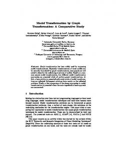
The Eclipse Modeling Framework (EMF) [2] has evolved to one of the standard technologies to define modeling languages. EMF provides a modeling and code generation framework for Eclipse applications based on structured data models. The modeling approach is similar to that of MOF, actually EMF supports Essential MOF (EMOF) as part of the OMG MOF 2.0 specification. Containment relations, i.e. aggregations, define an ownership relation between objects. Thereby, they induce a tree structure in model instantiations. In [5], we consider EMF instance models1 as typed graphs with special containment edges. Typing is expressed by a type graph. It has some similarities to a meta-model, but does not contain multiplicities and other constraints. For simplicity, we consider type graphs without inheritance in this paper. For a complete definition of EMF model transformation based on type graphs with inheritance, see [5]. Since the containment concept plays a special role in EMF models, we distinguish a special kind of edge types defining containments in the type graph. Example 1 (EMF Model for statecharts with AND-States). Fig. 1 shows the EMF model for statecharts with AND-states, where an arbitrary number of states may be grouped in orthogonal regions of the same AND-state.
Fig. 1. EMF model for statecharts with AND-states
A State may contains Regions, each of them containing States again. We attribute States by Boolean flags denoting whether they are initial or final states. States are connected by Transitions which are triggered by Events. For simulation, a Current object is needed which is linked to the currently active States. The Current object receives an Event, the first element of a queue (Events linked by next links). The type graph with containment corresponding to the EMF model 1
Note that the EMF community uses the terms “EMF model” for meta-model and “EMF instance model” for a model conforming to a meta-model.
62
Enrico Biermann, Claudia Ermel, Gabriele Taentzer
in Fig. 1 looks like the EMF model but has no multiplicities. We have six containment edge types (three of them have type Statechart as source, type states starts from type Region and type reg starts from type State). Types states and reg could lead to cycles in EMF instance models (corresponding to graphs typed over the type graph), because there could be theoretically a Region r which contains a State which transitively contains Region r again. Hence, we call such containment edge types cycle-capable. In consistent EMF instance graphs, each object node has at most one container and no containment cycles do occur. Graphs fulfilling these requirements are called graphs with containment. Although EMF instance models do not need to be rooted in general, this property is important for storing them, or more general, to define the model’s extent. Definition 2 (Graph with containment (C-graph)). A graph with containment, short C-graph, is a graph G = (GN , GE , sG , tG ) with a distinguished set of containment edges GC ⊆ GE . The containment edges induce the following binary relation containsG (the transitive closure of GC ): – containsG = {(x, y) ∈ GN × GN | ∃e ∈ GC : (sG (e) = x ∧ tG (e) = y) } ∪ {(x, y) ∈ GN × GN | ∃z ∈ GN : (x containsG z ∧ z containsG y)} All containment edges must fulfill the following properties (containment constraints): – e1 , e2 ∈ GC : tG (e1 ) = tG (e2 ) ⇒ e1 = e2 (at most one container). – (x, x) ∈ / containsG for all x ∈ GN (no containment cycles). If G is typed over a type graph T G, there is a typing morphism type : G → T G which is consistent with containment, i.e. ∀e ∈ GC : typeGE (e) ∈ T GC . Please note that a type graph T G is no C-graph in general (see e.g. our type graph for statecharts in Fig. 1, which has a containment cycle). Definition 3 (Rooted graph). A C-graph G is called rooted, if there is a node r ∈ GN , called root node, such that ∀x ∈ GN with x 6= r : r containsG x. Example 4 (Consistent EMF instance graph). Fig. 2 shows a statechart with an AND-state. We model an ATM (automated teller machine) where the user can insert a bank card and, after the input of the correct pin, can draw a specified amount of cash from her or his bank account. The display region of the ANDstate shows what is being displayed on screen, and, simultaneously, the card-slot component models whether the card slot is holding a bank card or not. The enter event triggers the transition before the AND-state to enter the AND-state. The card-sensed event happens if the sensor has sensed a user’s bank card being put into the card slot. This event triggers two transitions in parallel. The next events (pin-input, pin-ok and amount-input) are local to the display region. The end event again triggers two transitions if the current state is any but the welcome
Lifting Parallel Graph Transformation Concepts. . .
63
Fig. 2. EMF instance graph: a statechart modelling an ATM
state for the display region and holding for the card-slot region. Then, the final states are reached and the AND-state can be left if the leave event happens. Fig. 3 shows the abstract syntax of the EMF instance graph corresponding to the ATM statechart in Fig. 2. This instance graph is typed over the type graph in Fig. 1. The initial state where we want to start the simulation is the start state before the AND-state ATM is entered. The Current object points to the start state and is linked to an initial event queue consisting so far of the single event enter (the event needed to enter the AND-state) followed by the special event denoting the queue end. During the simulation, events may be added to the event queue such that the queue holds the events that should be processed during the simulation. For better readability, we write names which are not empty in quotation marks and put the name of a boolean attribute type (Initial or Final) if its value is true. Furthermore, we omitted the containment edges in Fig. 3 from the Statechart object named ATM-SC to all Current and Event objects, and from the Region objects to the corresponding Transition objects. The EMF instance graph in Fig. 3 is a C-graph since each object is contained in at most one container and there are no containment cycles. The C-graph is rooted, as the root node is the Statechart object named ATM-SC which contains all objects transitively.
3
EMF Model Transformations with Multi-Object Structures
EMF models can be manipulated by several approaches to rule-based model transformations. A transformation framework for EMF models which follows the concepts of algebraic graph transformation [4] as far as possible, is presented in [6]. But EMF model transformations do not always behave like algebraic graph transformation. The main reason is the difficulty to always satisfy the containment constraints of EMF. Hence, in our previous paper [5], we identify a kind
64
Enrico Biermann, Claudia Ermel, Gabriele Taentzer
Fig. 3. Abstract Syntax of the ATM statechart in Fig. 2 with Current pointer
of model transformation rules which lead to consistent EMF model graphs (i.e. fulfilling the containment constraints), if applied as normal graph transformation rules to consistent EMF model graphs. Thus, we identify a kind of EMF model transformations which behave like algebraic graph transformations. The advantage of this approach is that we provide a basis to apply the rich theory of algebraic graph transformation [4, 11–13] to EMF model transformations. In Section 3.1, we shortly review the basic notions from [5]. We then introduce amalgamated EMF model transformation, i.e. EMF model transformation with multi-object structures, based on parallel graph transformation concepts in Section 3.2 and expand the capability of consistent EMF transformations by showing that the application of an amalgamated EMF model transformation rule to a consistent EMF model graph results in a consistent transformed EMF model graph again.
Lifting Parallel Graph Transformation Concepts. . . 3.1
65
Consistent EMF Model Transformation Based on Graph Transformation Concepts
In order to precisely define consistent graph rules, we have to define relations between typed C-graphs, so-called C-graph morphisms. They define mappings of nodes and edges respectively, such that they are compatible with typing, source and target functions (like typed graph morphisms) and especially preserve containment edge types. Definition 5 (C-graph morphism). Given two C-graphs G, H, a pair of functions (fN , fE ) with fN : GN → HN and fE : GE → HE forms a valid C-graph morphism f : G → H, if it has the following properties: – fN ◦ sG (e) = sH ◦ fE (e), fN ◦ tG (e) = tH ◦ fE (e), and – ∀e ∈ GC ⇒ fE (e) ∈ HC (containment edges are preserved). If G and H are typed over T G, f must be type compatible, i.e. typeG = typeH ◦f . If fN and fE are inclusions, then G is called a subgraph of H, denoted by G ⊆ H. Definition 6 (Graph rule). A graph rule typed over a type graph T G is given by r = (L ⊇ K ⊆ R, type, N AC), where L, K and R are C-graphs, type is a triple of typing morphisms type = (typeL : L → T G, typeK : K → T G, typeR : R → T G), and N AC is a set of pairs N ACi = (Ni , typeNi ), i ∈ N with L ⊆ Ni , and typeNi : Ni → T G a typing morphism, such that typeL ⊇ typeK ⊆ typeR . As a drawing convention, we omit K. All objects with equal numbers in L and R are also in K and are preserved when the rule is applied. A rule p can contain one or more negative application conditions (NACs) denoting situations which must not exist for the rule to be applicable. Formally this is expressed by attributed graphs N ACi and morphisms ni : N ACi ← L. A rule is applicable to a graph G at a match m : L → G if there is no injective C-graph morphism n0i : N ACi → G such that m = n0i ◦ ni for all i ∈ I. The application of rule r to r graph G leads to the derivation of a graph H. Formally, a derivation G =⇒ H is a DPO construction in the category of typed attributed graphs and graph morphisms. Example 7 (Graph rule). Rule addEvent(e), shown in Fig. 4, allows to add a new event of name e into the event queue. In this way, the events that should be processed during a simulation run, can be defined in the beginning of the simulation. Moreover, events also can be inserted while a simulation is running. Now we define a special kind of graph transformation which formalizes a form of EMF model transformation leading always to EMF models consistent with typing and containment constraints. For that purpose, the form of allowed transformation rules has to be restricted. Consistent transformation rules allow the following kinds of actions which change containments: 1. Delete an object node with its containment relation.
66
Enrico Biermann, Claudia Ermel, Gabriele Taentzer
Fig. 4. Rule addEvent(e) to insert Event e into the Event Queue
2. Create a new object node and connect it immediately to its container. 3. Delete a containment edge together with its contained object node or change the container of a preserved object node. 4. Create a containment edge with the contained object node or change the container of an existing object node. 5. For an object node contained via a cycle-capable containment edge, change its container only, if the old and the new container of the object node were already transitively related by containment. In the following definition, we formalize all actions that preserve consistent containment relations which have been described above. 0 := RC − Definition 8 (Consistent graph rule). Let L0C := LC − KC , RC 0 0 KC , LN := LN − KN and RN := RN − KN . A graph rule p = (L ⊇ K ⊆ R, type, N AC) is consistent wrt. containment if for each rule all of the following constraints are satisfied:
1. (node deletion) ∀n ∈ L0N : ∃e ∈ L0C with tL0C (e) = n, 0 0 2. (node creation) ∀n ∈ RN : ∃e ∈ RC with tR (e) = n, 3. (containment edge deletion) ∀e ∈ L0C with tL (e) = n: 0 with tR (e0 ) = n) ∨ (n ∈ KN ∧ ∃e0 ∈ RC n ∈ L0N 0 4. (containment edge creation) ∀e ∈ RC with tR (e) = n: 0 ∨ (n ∈ KN ∧ ∃e0 ∈ L0C with tL (e0 ) = n) n ∈ RN 5. (creation of cycle-capable containment edges) 0 with sR (e) = n∧tR (e) = m : ∃e0 ∈ L0C with sL (e0 ) = o∧tL (e0 ) = m : ∀e ∈ RC ((o, n) ∈ containsL ∧ (m, n) ∈ / containsL ) ∨ (n, o) ∈ containsL Note that for item 5 (creation of cycle-capable containment edges), it is sufficient to inspect the containment in the rule’s left-hand side. There cannot be a containment edge from the matched node m to n in G, because then n would have two containers m and o, and hence G would not be a C-graph. Example 9 (Consistent graph rules). Rule addEvent(e) from Example 7 is a consistent graph rule since for each created object its containment edge is created as well. Two further rules are depicted in Fig. 5 which process sequential transitions outside of AND-states. Rule sequentialTransition processes a transition in the current state which is triggered by the current event. This rule is consistent since the removed event node is deleted together with its containment
Lifting Parallel Graph Transformation Concepts. . .
67
edge. Rule skipEvent models the situation that no transition is triggered by the current event. In this case, the event is removed from the event queue. Again, the event is deleted together with its containment edge.
Fig. 5. Rules sequentialTransition and skipEvent
In our main theorems in [5], we show that the application of a consistent graph rule to a consistent (rooted) EMF instance graph always results again in a consistent (rooted) EMF instance graph. Theorem 10 (Consistent graph transformation step). Given a consistent m graph rule p = (L ⊇ K ⊆ R, type, N AC) and a match L −→ G to a C-graph G which is typed by typeG : G → T G and satisfies N AC. Then, the result graph p,m (H, typeH ) of direct transformation (G, typeG ) =⇒ (H, typeH ) is a C-graph. Proof. See [5]. Theorem 11 (Rooted graph transformation step). A consistent graph p,m transformation step (G, typeG ) =⇒ (H, typeH ) leads to a rooted result graph H if graph G is rooted. Proof. See [5].
68 3.2
Enrico Biermann, Claudia Ermel, Gabriele Taentzer Consistent EMF Model Transformations with Multi-Object Structures
In this section, we lift the essential concepts of parallel graph transformation [8] to EMF model transformation and also lift the consistency result for EMF model transformations from Section 3.1 to transformations with multi-object structures which we also call amalgamated EMF transformations. Using parallel graph transformation, a system state modeled by a graph can be changed by several actions executed in parallel. Since graph transformation is rule-based without restrictive execution prescription, parallel graph transformation offers the possibility for massively parallel execution. The synchronization of parallel rule applications is described by common subrules, called kernel rules. The simplest type of parallel actions is that of independent actions. If they operate on different objects they can clearly be executed in parallel. If they overlap just in reading actions on common objects, the situation does not change essentially. In graph transformation, this is reflected by a parallel rule which is a disjoint union of rules. The overlapping part, i.e. the objects which occur in the match of more than one rule, is handled implicitly by the match of the parallel rule. As the application of a parallel rule can model the parallel execution of independent actions only, it is equivalent to the application of the original rules in either order [7]. If actions are not independent of each other, they can still be applied in parallel if they can be synchronized by subactions. If two actions contain the deletion or the creation of the same node, this operation can be encapsulated in a separate action which is a common subaction of the original ones. A common subaction is modelled by the application of a kernel rule of all additional actions (modelled by multi-rules). The application of rules synchronized by kernel rules is then performed by gluing multi-rule instances at their kernel rules which leads to the corresponding amalgamated rule. The application of an amalgamated rule is called amalgamated graph transformation. Formally, the synchronization possibilities of actions (multi-rule applications) are defined by an interaction scheme. For consistent amalgamated EMF transformations (also called EMF model transformations with multi-object structures), we need consistent interaction schemes where all rules are consistent. Definition 12 (Consistent Interaction Scheme). An interaction scheme I = (rK , M, ke) consists of a kernel rule rK , a set M = {ri |1 ≤ i ≤ n} of rules called multi-rules, and a set ke of kernel rule embeddings kei : rK → ri into the multi-rules (i.e. rK is subrule of all multi-rules). I is consistent, if all rules are consistent. Example 13. An example of the construction of an amalgamated EMF transformation rule from an interaction scheme is given in Fig. 6. The common sub-action (adding a loop to a object 1) is modeled by kernel rule rK . We have only one multi-rule r1 modeling that at each possible match (the blue) object 2 shall be deleted together with its containment edge, and a new (red) object shall be inserted such that it is contained in object 1. Both the
Lifting Parallel Graph Transformation Concepts. . .
69
Fig. 6. Construction of an amalgamated graph rule
kernel-rule and the multi-rule are consistent, and we have a subrule embedding from the kernel rule to the multi-rule given by the three C-graph morphisms LK → L1 , KK → K1 and RK → R1 . Given graph G, we have obviously three different matches from the multi-rule r1 to G which overlap in the match from the kernel rule to G. Hence, we have three multi-rule instances, each of them with a different match to G. Gluing the multi-rule instances at their common kernel rule, we get the amalgamated rule with respect to G, shown at the bottom of Fig. 6. The amalgamated rule contains the common action and, additionally, all actions from the multi-rules that do not overlap. Dashed arrows in Fig. 6 indicate rule embedding morphisms, embedding the kernel rule into the corresponding instances of the multi-rules, and the multi-rules into the amalgamated rule. In addition to specifying how multi-rules should be synchronized, we must decide where and how often a set of multi-rules should be applied. The basic way to synchronize complex parallel operations is to require that a rule should be applied at all different matches it has in a given graph (expressing massively parallel execution). In this paper, we restrict the covering of G (the image of all different matches from instances of multi-rules in G) to all different matches of multi-rules that overlap in the match of their common kernel rule and do not overlap anywhere else. For more complex covering constructions see [8]. Definition 14. (Amalgamated EMF model transformation rule) Given a consistent interaction scheme I = (rK , {ri |1 ≤ i ≤ n}, ke) with (Li − LK ) ∩ (Lj − LK ) = ∅ and a match mK for the kernel rule rK . An amalgamated
70
Enrico Biermann, Claudia Ermel, Gabriele Taentzer
EMF model transformation rule rA = (LA ← KA → RA ) is an EMF model transformation rule where as many copies riji of multi-rules ri are joined as there are different matches miji : Li → G such that the copies riji of ri in rA all overlap at kernel rule rK and the matches miji overlap at match mK only. We speak of amalgamated EMF model transformation (or, alternatively, of EMF model transformation with multi-object structures) if the definition of the EMF model transformation is given by consistent interaction schemes. In this case, the application of an amalgamated EMF model transformation rule defines an EMF model transformation step. Note that a special interaction scheme consists of only one rule, i.e. a kernel rule, such that the interaction scheme is applied like a usual sequential rule. In order to show that EMF instance graphs resulting from amalgamated EMF model transformation are consistent (Theorem 15), we construct the amalgamated rule from a given consistent interaction scheme and show that this amalgamated rule is a consistent graph rule. Afterwards, we can apply Theorem 10. Theorem 15. Given a consistent interaction scheme I = (rK , {ri |1 ≤ i ≤ n}, ke) and matches mk and mi to G for all 1 ≤ i ≤ n. Then, if G is a Cgraph, the resulting amalgamated EMF model transformation rule is consistent. Proof. Case n = 0: No multi-rule is applied. The amalgamated rule rA is equal to the kernel rule rK , which is consistent by assumption (I is consistent). Case n = 1: There is one application of a multi-rule. The amalgamated rule rK is equal to this multi-rule, thus it is consistent by assumption. Case n > 1: We have to show that the amalgamated rule rA satisfies all five consistency constraints for EMF rules according to Def. 8: 1. (node deletion) To show: ∀n ∈ L0AN : ∃e ∈ L0AC with tL0A (e) = n. C W.l.o.g. n ∈ L0iN : Then, there is e ∈ L0iC with tL0i (e) = n, since ri is C consistent. 0 0 2. (node creation) To show: ∀n ∈ RA : ∃!e ∈ RA with tRA (e) = n. N C 0 W.l.o.g. n ∈ RiN : Then, there is a unique e ∈ Ri0 C with tRi0 (e) = n, since C 0 ri is consistent. There cannot be another e ∈ RA with tRA (e) = n, since C the assumption allows an overlap of multi-rules in the kernel rule only. In this case, they would have to overlap in node n, too, which is not necessarily required here. 3. (containment edge deletion) To show: ∀e ∈ L0AC with tLA (e) = n: 0 n ∈ L0AN ∨ (n ∈ KAN ∧ ∃e0 ∈ RA with tRA (e0 ) = n). C W.l.o.g. e ∈ L0iC with tLi (e) = n. Then, n ∈ L0iN ∨ (n ∈ KiN ∧ ∃e0 ∈ Ri0 C with tRi (e0 ) = n), since ri is consistent. 0 4. (containment edge creation) To show: ∀e ∈ RA with tRA (e) = n: C 0 0 0 n ∈ RAN ∨ (n ∈ KAN ∧ ∃e ∈ LAC with tLA (e0 ) = n)
Lifting Parallel Graph Transformation Concepts. . .
71
W.l.o.g. ∀e ∈ Ri0 C with tRi (e) = n. Then, n ∈ Ri0 N ∨ (n ∈ KiN ∧ ∃e0 ∈ L0iC with tLi (e0 ) = n), since ri is consistent. 5. (creation of cycle-capable containment edges) 0 To show: ∀e ∈ RA with sRA (e) = n ∧ tRA (e) = m : ∃e0 ∈ L0AC with C Cycle
sLA (e0 ) = o ∧ tLA (e0 ) = m : ((o, n) ∈ containsLA ∧ (m, n) ∈ / containsLA ) ∨ (n, o) ∈ containsLA . W.l.o.g. e ∈ Ri0 C with sRi (e) = n ∧ tRi (e) = m. Then, there is e0 ∈ L0iC Cycle with sLi (e0 ) = o ∧ tLi (e0 ) = m : ((o, n) ∈ containsLi ∧ (m, n) ∈ / containsLi ) ∨ (n, o) ∈ containsLi . In addition, we have to show that there is no (m, n) ∈ containsLj for some / j 6= i. Since ri and rj overlap in rK only, m, n ∈ L0KN ⊆ L0iN and (m, n) ∈ containsLi =⇒ (m, n) ∈ / containsLj . Corollary 16. Given a consistent interaction scheme I = (rK , {ri |1 ≤ i ≤ n}, ke) and matches mk and mi to G for all 1 ≤ i ≤ n. Then, if G is a C-graph, the result graph H after applying interaction scheme I to G is a C-graph as well. Proof. Due to Theorem 15, the amalgamated rule constructed from I is consistent. By Theorem 10, consistent rules preserve C-graphs. Hence, the result graph H is again a C-graph. Corollary 17. Given a consistent interaction scheme I like in Corollary 16. Then, if G is a rooted C-graph, the result graph H after applying the interaction scheme I to G is a rooted C-graph as well. Proof. Due to Theorem 15, the amalgamated rule constructed from I is consistent. By Theorems 10 and 11, we know that consistent rules preserve C-graphs and the rootedness of C-graphs. Hence, the result graph H is a rooted C-graph. Example 18 (Simulator for statecharts with AND-States). In our statecharts variant, every region belonging to an AND-state has exactly one initial state and at least one final state. The intended semantics for our statecharts requires that if an AND-state is reached, the active states become the initial ones of each region. A transition is processed if its pre-state is active and its triggering event is the same as the event which is received by the Current object (the first event in the queue). Afterwards, the state(s) following the transition become(s) active, the event of the processed transition is removed from the queue, and the previously active state(s) (the pre-state(s) of the transition) is/are not active anymore. More than one transition are processed simultaneously if they belong to different regions of the same AND-state, if their pre-states are all active and if they are all triggered by the same event which is received by the Current object. All regions belonging to the same AND-state must have reached a final state before the AND-state can be left and the transition from the AND-state to the next state can be processed. For our simulator we use the Current object not only as object which receives the next event (and is linked to the event queue) but also as pointer to the current active states.
72
Enrico Biermann, Claudia Ermel, Gabriele Taentzer
Thus, our simulation rules model the relinking of the Current object to the next active states and the updating of the event queue. Note that in the following screenshots of interaction schemes we use an integrated notation, where we define the kernel rule and one multi-rule within one rule picture. This is possible since each of our interaction schemes consists of a kernel rule and one multi-rule only. We distinguish objects belonging to the multi-rule by drawing them as multi-objects (with indicated multiple boxes instead of simple rectangles). The kernel rule consists of all simple objects which are not drawn as multiple boxes. All arcs adjacent to multi-objects belong to the multi-rule only, but not to the kernel rule. All multi-objects together with their adjacent arcs in one multi-rule form a multi-object structure. The upper part of Fig. 7 shows the interaction scheme enterRegion which moves the Current pointer along a transition that connects a state to an ANDstate. In this case, the Current pointer has not only to point to the AND-state afterwards but also to all initial states of all regions of the AND-state. Hence, the amalgamated rule consists of as many copies of the multi-rule as there are regions in the AND-state (provided that each component has exactly one initial state which has to be ensured by a suitable syntax grammar).
Fig. 7. Interaction Schemes enterRegion and leaveRegion
Vice versa, when an AND-state is left, the Current pointer has to be removed from all of its regions. This step is realized by the interaction scheme leaveRegion at the bottom of Fig. 7. The fact that the active states of all regions have to be Final is modelled by the NAC. The multi-rule models how all inner links from the Current pointer to the regions’ final states are removed.
Lifting Parallel Graph Transformation Concepts. . .
73
A simultaneous transition is modelled by interaction scheme simultanTrans in Fig. 8. Here, an arbitrary number of transitions in different regions of an ANDstate are processed if triggered by the same event. In our ATM example this happens at different points of the simulation: When the AND-state is entered and the event card-sensed is happening, then the two first transitions of the two regions are processed simultaneously. Similarly, at any state of the display the user can abort the transaction: the end event triggers the return of the display region to state welcome and the return of the card-slot region to state empty.
Fig. 8. Interaction Scheme simultanTrans
The simultanTrans interaction scheme is a good example for a concise way to model simultaneous transitions which are triggered by a single event. This would be quite difficult to model using simple rules. Note that this scheme is applicable also for sequential transition processing within an AND-state. Then there is only one copy of the multi-rule, similar to rule sequentialTrans. In the case that no transition leaving an active state is triggered by the current event, we have the situation that there is no copy of the multi-rule of simultanTrans, but the kernel rule can be applied anyway. This means that an event which does not trigger any transition inside of an AND-state simply is removed from the event queue. Again, this is similar to applying rule skipEvent with the difference that regions are used here.
4
Related Work
There are two tool-based approaches known to us which also realize parallel graph transformation: AToM3 and GROOVE, where AToM3 supports the explicit definition of interaction schemes in different rule editors [14] and GROOVE implements rule amalgamation based on nested graph predicates [15]. A related conceptual approach aiming at transforming collections of similar subgraphs is presented in [16]. The main conceptual difference is that we amalgamate rule instances whereas the authors of [16] replace all collection operators (multi-object structures) in a rule by the mapped number of collection match copies. Similarly, Hoffmann et al. define a cloning operator in [17] where cloned nodes
74
Enrico Biermann, Claudia Ermel, Gabriele Taentzer
correspond to multi-objects, but complete multi-object structures cannot be described. Moreover, the graph transformation tools PROGRES [18] and FuJaBA [19] feature so-called set nodes which are duplicated as often as necessary, but are not based on amalgamated graph transformation. None of the related approaches support the transformation of EMF models.
5
Conclusions and Future Work
This paper presented amalgamated EMF transformation as a valuable means for modelling and simulation. They extend the capabilities of EMF transformation based on simple graph transformation [5] by allowing parallel execution of synchronized EMF transformation rules. This is useful for specifying simulators for formalisms in which parallel actions happen. This is the case for a great number of formalisms, such as statecharts with AND states. It has been shown in the paper that amalgamated EMF transformation always leads to consistent EMF instance models which satisfy the containment constraints of EMF. In the future, we plan to apply the approach to other kinds of EMF model transformations, such as model refactorings, where multi-object structures are found frequently. Amalgamated EMF transformation are currently being implemented in the tool EMF Tiger [10, 6] (Transformation generation), a recently developed Eclipse plug-in supporting modeling and code generation for EMF model transformations, based on structured data models and graph transformation concepts. The goal of EMF Tiger is to provide the means to graphically define rule-based transformations on EMF models. Rule applications change an EMF model instance in-place, i.e. an EMF instance model is modified directly, without copying it before. Moreover, control of rule applications is supported by EMF Tiger, as well as pre-definition of (parts of) the match. EMF Tiger currently consists of a graphical editor for visually defining EMF model transformation rules, and a compiler, generating Java code from these transformation rules to be included into existing projects performing EMF model transformation. It also contains an interpreter which translates EMF transformation rules to AGG. This interpreter is useful for verification purposes.
References 1. Mens, T., Tourw´e, T.: A survey of software refactoring. Transactions on Software Engineering 30(2) (February 2004) 126–139 2. Eclipse Consortium: Eclipse Modeling Framework (EMF) – Version 2.4. (2008) http://www.eclipse.org/emf. 3. Object Management Group: Meta Object Facility (MOF) Core Specification Version 2.0. http://www.omg.org/technology/documents/modeling_spec_catalog. htm\#MOF (2008) 4. Ehrig, H., Ehrig, K., Prange, U., Taentzer, G.: Fundamentals of Algebraic Graph Transformation. EATCS Monographs in Theor. Comp. Science. Springer (2006)
Lifting Parallel Graph Transformation Concepts. . .
75
5. Biermann, E., Ermel, C., Taentzer, G.: Precise Semantics of EMF Model Transformations by Graph Transformation. In Proc. Conf. on Model Driven Engineering Languages and Systems (MoDELS’08). Vol. 5301 of LNCS., Springer (2008) 53–67 6. Biermann, E., Ehrig, K., K¨ ohler, C., Kuhns, G., Taentzer, G., Weiss, E.: Graphical Definition of In-Place Transformations in the Eclipse Modeling Framework. In Proc. Conf. on Model Driven Engineering Languages and Systems (MoDELS’06). Vol. 4199 of LNCS. Springer (2006) 425–439 7. Ehrig, H., Kreowski, H.J.: Parallel graph grammars. In Lindenmayer, A., Rozenberg, G., eds.: Automata, Languages, Development. North Holland (1976) 425–447 8. Taentzer, G.: Parallel and Distributed Graph Transformation: Formal Description and Application to Communication-Based Systems. PhD thesis, TU Berlin (1996) 9. B¨ ohm, P., Fonio, H.R., Habel, A.: Amalgamation of graph transformations: a synchronization mechanism. Journal of Computer and System Science 34 (1987) 377–408 10. Tiger Project Team, Technische Universit¨ at Berlin: EMF Tiger (2009) http:// tfs.cs.tu-berlin.de/emftrans. 11. Ehrig, H., Kreowski, H.J., Montanari, U., Rozenberg, G., eds.: Handbook of Graph Grammars and Computing by Graph Transformation. Vol 3: Concurrency, Parallelism and Distribution. World Scientific (1999) 12. Ehrig, H., Engels, G., Kreowski, H.J., Rozenberg, G., eds.: Handbook of Graph Grammars and Computing by Graph Transformation, Vol. 2: Applications, Languages and Tools. World Scientific (1999) 13. Rozenberg, G.: Handbook of Graph Grammars and Computing by Graph Transformations, Vol. 1: Foundations. World Scientific (1997) 14. de Lara, J., Ermel, C., Taentzer, G., Ehrig, K.: Parallel Graph Transformation for Model Simulation applied to Timed Transition Petri Nets. In: Proc. Graph Transformation and Visual Modelling Techniques (GTVMT) 2004. (2004) 15. Rensink, A., Kuperus, J.H.: Repotting the geraniums: On nested graph transformation rules. In: Int. Workshop of Graph Transformation and Visual Modelling Techniques (GT-VMT’09). (2009) 16. Grønmo, R., Krogdahl, S., Møller-Pedersen, B.: A collection operator for graph transformation. In: Int. Conf. on Model Transformation (ICMT’09). (2009) 17. Hoffmann, B., Janssens, D., van Eetvelde, N.: Cloning and expanding graph transformation rules for refactoring. In: Int. Workshop on Graph and Model Transformation (GraMoT’05). Vol. 152 of ENTCS, Elsevier (2006) 53–67 18. Sch¨ urr, A., Winter, A., Z¨ undorf, A.: The PROGRES-approach: Language and environment. In [12]. 19. Fischer, T., Niere, J., Torunski, L., Z¨ undorf, A.: Story diagrams: A new graph rewrite language based on the UML. In Proc. Workshop on Theory and Application of Graph Transformation. Vol. 1764 of LNCS, Springer (2000) 296–309 ..................................................................................... Enrico Biermann Institut f¨ ur Softwaretechnik und Theoretische Informatik Technische Universit¨ at Berlin D-10587 Berlin (Germany)
[email protected] .....................................................................................
76
Enrico Biermann, Claudia Ermel, Gabriele Taentzer
..................................................................................... Dr. Claudia Ermel Institut f¨ ur Softwaretechnik und Theoretische Informatik Technische Universit¨ at Berlin D-10587 Berlin (Germany)
[email protected] http://tfs.cs.tu-berlin.de/˜lieske Hans-J¨ org was the external examiner of Claudia Ermel’s doctoral thesis. ..................................................................................... Prof. Dr. Gabriele Taentzer Fachbereich Mathematik und Informatik Philipps-Universit¨ at Marburg D-35032 Marburg (Germany)
[email protected] http://www.informatik.uni-marburg.de/˜taentzer Hans-J¨ org was the external examiner of Gabriele Taentzer’s doctoral thesis at the Technical University of Berlin. Due to their common research interests in graph transformation and visual languages, they have several joint publications. .....................................................................................