Keywords: Electric Vehicle, Energy Management, Fuzzy Logic ... an energy management point of view, both islanded microgrids and EVs have a limited amount ...
Load Control Algorithm for Efficient Energy Management in Electric Vehicles Ilya Kavalchuk1, Mohhamedmehdi Seyedmahmoudian1, Ben Horan1, Aman Maung Than Oo1, Alex Stojcevski2 1) Deakin University, School of Engineering, Australia 2) RMIT Vietnam, Abstract There are two trends in vehicle developments which have been prevalent during the last decade. The first is the increase in the number of electric zero emission vehicles. The second is the advancement of the electronic and electrical systems aiming to increase the safety and comfort of the vehicles. Zero emissions transport characterise as a vehicle with limited available amount of energy resources available for on board usage due to the energy storage systems limitations where increasing number of systems requires more energy to operate. This paper covers problem of the onboard energy management for Electric Vehicles base on the centralised controller.
Keywords: Electric Vehicle, Energy Management, Fuzzy Logic 1. INTRODUCTION The systems on-board modern vehicles have become more complicated as more systems have been developed and introduced. Recently developed systems aim to not only improve the comfort of the occupant, but also the safety of the people in and around the vehicle. At the same time, there is also a drive to improve the efficiency of vehicles and to reduce fuel consumption and, as a result, the emissions produced by the engine. Electric vehicles (EV) are one possible solution to move away from fossil fuel powered vehicles. The combination of the renewable electric power sources, energy storage systems (ESS) and electric vehicles, contribute to achieving an environmentally friendly and pollution free transportation. The increasing number of electrical systems integrated into EVs and their power consumption, and energy storage capacity limitations can decrease the performance of EVs. A common solution to this is to analyse the ESS and develop new types of ESS devices. Researchers are proposing utilisation of the new generation of batteries [1], as well as combining existing battery technology with fuel cells or ultra-capacitors to realise a hybrid ESS [2]. Reducing energy consumption and smart energy management systems for EVs however has not received as much interest as it may deserve. Several studies have proposed the application of smart grid technologies to the protection systems in EVs [3-5]. The drivetrain consumes the most energy of the devices within an EV. There has been a significant amount of research into drivetrain power management [6-8]. Examples of this include control of the drivetrain operations using fuzzy logic [5], sliding mode control [9] and genetic algorithms [10]. Aside from consuming the majority of an EV’s available energy, the drivetrain can also produce power through regenerative braking [11]. In parallel to the movement towards more electric vehicles, small islanded electrical networks which can operate on purely renewable energy sources are receiving increasing interest. Islanded microgrids are the systems, which operate only on the internally generated renewable energy with the limited reliance on power from external sources such as the grid. Local energy can be produced by photovoltaic and wind generation systems and then stored in batteries for the low solar/wind availability time. There are also several studies, which demonstrate smart energy management systems for islanded microgrids to manage and balance generation and consumption of the energy within the closed island with limited power from the grid [12, 13]. There are two main approaches to microgrid energy management architecture: centralised and decentralised. Centralised microgrid systems are based on a single central energy monitoring system, where users supply this controller with information regarding energy usage and generation and, storage capabilities [14]. Decentralised microgrid systems, on the other hand, consider each house as a controller, which is connected with the grids and communicates regarding load sharing and energy usage in real-time [15]. Given the limitations to their energy supply, electric vehicles can be considered as similar to islanded microgrids. From an energy management point of view, both islanded microgrids and EVs have a limited amount of energy which is stored in battery storage and the on-board energy storage system respectively, which needs to be managed strategically. This paper considers the use of a centralised approach to energy management such as that used for islanded microgrids, for improving energy efficiency, controllability and utilisation in EVs. In practice this would relate to displacing the controllers from being located with the considered vehicle systems and locating these centrally. The International Conference on Automotive Technology for Vietnam - ICAT2015
1/9
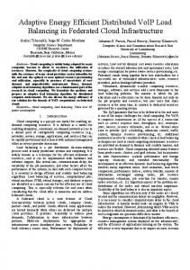
The first part of the paper discusses typical power requirements of the various systems as well as their duration of operation so as to develop the required load profiles. The second part of the paper focuses on bus design and physical implementation of the decentralised control architecture. The third part introduces a fuzzy logic controller for control of centralised energy management system. 2. POWER REQUIREMENTS AND LOAD PROFILES OF THE SYSTEMS The growing number of systems in modern transportation systems increase the complexity in understanding the energy requirements and load profiles of the individual systems. There are different ways to classify the systems. In this paper, the primary classification is based on the function and importance of the systems. Based on these parameters, the systems were categorised into passive safety, active safety, heating ventilation air conditioning (HVAC), lighting, indicators and wipers, occupant comfort, and entertainment systems. Further classification can be made based on the power requirements and duration of operation as the main variables for the energy consumption. 2.1. Active Safety Systems Active safety systems are systems which assist drivers in the challenging conditions and help to prevent the accidents on the road. The active safety systems considered herein are the power steering mechanism and the braking system including its components and sensors. Given their purpose, these systems are considered to have the highest importance and should always have enough power to operate under any circumstances. The power consumption of these systems depends on the components employed. Electric power steering mechanisms employ an electric motor which sits on the steering shaft. The duration of operation is equal to the duration of operation of the vehicle. Herein we define duration of operation to be the assumed fraction of time the system operates in relation to the total time the vehicle is being operated. The power supplied to this motor needs to be sufficient to steer the wheels across the range of possible vehicle velocities and requested rotational velocities of the steering shaft. Based on [13] the power requirements for the steering motor should be around 2kW. The braking systems in EVs consist of two separate systems. The first is the regenerative braking system, which operates on the powertrain power bus and supplies power back to the EV.. Given that electric motors are not able to produce enough braking torque alone, hydraulic or pneumatic mechanisms are still required within the vehicle. The hydraulic brakes do not require additional power to operate as the braking pedal transmits pressure from the brake pedal to the braking callipers. There is however the need to provide electric power for electronic stability control (ESC) and anti-lock bracking systems (ABS) which are operate based on high pressure pumps. ABS/ESC also use sensors to calculate the rotational speed of the wheels and computer units for performing calculations. The total required power for the braking systems is around 100W, where the majority of the power is used to operate the pump to vary the pressures within. The duration of operation of the braking systems are dependent on driving conditions. Slippery roads combined with a high number of stops (such as encountered in stop-start city driving), may result in a duration of operation of up to 10% of total driving time [16]. Fig. 1 shows the connectivity of the active safety systems considered, their power requirements and duration of operation.
Fig. 1. Active Safety Systems Power Requirements and Duration of Operation
2.2. Passive Safety Systems Passive safety systems prevent occupants from injury in accidents and are a high priority in the automotive industry. The main components of the passive safety systems are airbags, seatbelt pre-tensioner actuators and sensors. Piezo sensors are used to activate the airbags when collision is detected. The detected collision then initiates a small explosion to deploy the airbags. The piezo sensors need to be powered and supplying information to the system for the entire time the vehicle is operating (100% duration of operation). While the energy used to deploy the airbags can be considered from an energy management point of view as negligible, there must of course be enough energy in reserve at all time to be able to deploy the airbags and for the airbag’s real-time protection and monitoring systems. The International Conference on Automotive Technology for Vietnam - ICAT2015
2/9
Another power consuming device is the control unit of the system which operates for 100% of the time the vehicle is operating. This uses in the order of 10W of power based on [17]. The seat belt pre-tensioner system operates only in the case of emergency, but when it does have relatively high power requirements. Usually the power for each seat belt is no less than 100W, and this amount of power needs to be available in the case of an accident. Figure 2 shows the connectivity of the passive safety systems considered, their power requirements and their duration of operation.
Fig. 2. Passive Safety System Power Requirements and Duration of Operation
2.3. HVAC System Apart from the powertrain, the Heating, Ventilation and Air Conditioning systems are the highest consumers of energy in an EV. In contrast to conventional internal combustion powered vehicles, heating and AC systems both are require high amounts of electric power to heat and cool and for this reason the key components of HVAC system operate on the high voltage bus together with the drivetrain [18]. The main consumers of energy for the HVAC system are the fans, heating elements and air compressor pump. The fans are a critical part of the HVAC system and each fan requires 800-1000W peak power is dependent on the required rotational speed. Due to ventilation requirements for a vehicle, the duration of operation is equal to the total the vehicle is being operated. Despite operating the entire time the vehicle is running, according to research [19], peak power is only used for the starting procedure corresponding to 10% of total vehicle operating time. . The rest of the time, 20% from the peak power of the fan is enough to provide required air recirculation to prevent fogging of the windows. In terms of energy consumption, the heater is the second after the EV’s drive motor. The heater is the only source of the thermal energy to heat the cabin and, if necessary, parts of the powertrain, and because of the relatively low heat production by the electrical part of EVs, compared with the generated by internal combustion vehicles, the heating system may require up to 10kW peak of power. The duration of operation depends on the outdoor temperature and the vehicle cabin’s thermal insulation. The power required for the AC pump is lower than that for the heating element at around 3kW. The duration of operation for both the heating element and AC pump is high, but most time this element only needs to operate at 15-20% of the peak power to keep the temperature inside the vehicle constant. Additional heating elements can be installed to the front and rear windscreens. Such elements operate in the cold and foggy conditions to clear the windscreens and provide visibility. Each heating element can require 800W of power and have a 15% duration of operation. For passenger comfort additional heating elements may also be installed in the seats and steering wheel and the peak power requirements for such elements can be as high as 800 to1000W with a 15% duration of operation. An issue with HVAC systems in EVs is that their peak power occurs at the start of vehicle operation in order to provide comfortable conditions for the occupants. Once the requested temperature has been reached the system then uses much less power to maintain the climate. Figure 3 shows the connectivity of the considered EV’s HVAC systems, their power requirements and their duration of operation followed by the overall importance of the system.
The International Conference on Automotive Technology for Vietnam - ICAT2015
3/9
Fig. 3. HVAC System Power Requirements and Duration of Operation
2.4. Wipers and Lights The wipers and lights are two systems where energy consumption should be considered under specific conditions. For the wipers, these are required when there is rain, snowfall or the window is being cleared with wiper fluid, and the lights are required during the twilight and night time. These considerations affect the amount by which they are assumed to be powered during vehicle operation. In many countries day lights are required to be on for the entire time the car is in operation. Day lights however consume far less power than low and high beam heads lights, but due to 100% duration of operation makes them a critical consideration in any power consumption strategy. Other lights, such as stop, and tail lights and indicators operate for a longer amount of time than high beams. The introduction the LED lighting has significantly influenced power consumption required for lighting, however due cost and controllability considerations LED lighting has not yet become a common solution for vehicle lighting. The lights interior to the vehicle should also be considered. Because the required light output is low single LEDs are being used for internal vehicle lighting. Despite the low power because these lights are always on they constitute considerable energy consumption. Wipers are another important system which provides visibility to the driver in the conditions such as snow fall and rain. The power required for the main motor of a single wiper is approximately 150W. The importance of the wipers and lights can be considered higher than the multimedia or HVAC systems, but lower than the critical safety systems discussed earlier and for this reason are assigned an importance factor of 0.7. . As mentioned earlier, the duration of operation for the lights and wipers is dependent on circumstances. For example, in rainy conditions the wipers are working 100% of the time, and the same for lights for night time driving. For the purposes of this paper, designing the control logic, the duration of operation for the wipers can be assumed to be 15% of the duration of operation, 100% for day lights, and 30% equivalent duration of operation for low beam lights (taking into account high beam operation and day lights which remain on and contribute to night time lights). Figure 4 shows the power requirements of the lights and wipers and their duration of operation followed by the overall importance of the particular system.
Fig. 4. Lights and Wipers Power Requirements and Duration of Operation
2.5. Multimedia and Entertainment Systems The International Conference on Automotive Technology for Vietnam - ICAT2015
4/9
The growing number of different entertainment systems being introduced into vehicles combined with the widespread demand for support for mobile devices has an influence on power consumption in vehicles. Modern multimedia systems often incorporate medium to large touch screen interfaces which often operate 100% of the time and have a high-power consumption of 250W. These systems also commonly include GPS navigation systems and Bluetooth handsfree functionality which requires approximately 10W of power each with the duration of operation equal to the duration of operation of the vehicle. . In terms of power requirements, number of speakers and their peak power the largest influence on the overall system consumption. Music speakers can be divided into several classes based on the operational output frequency and, as a result, on the peak consumed power. Based on these classifications, speakers can be divided into three main classes: high frequency speakers with low power of 5- 10W and numbers of 2-4 for the vehicle, middle frequency speakers with medium power consumption of 20-25 W and numbers of 2-4 and the high power low frequency class with high power consumption of 40-100 W and the single speaker for the vehicle. For the middle size car, 2 high frequency and 4 medium frequency speakers are the standard features nowadays. The duration of operation of the speakers for normal conditions is equal to the duration of operation of the car. The difference is the consumed power, as normally all speakers operate on the 50% of the peak power to create comfortable level of the music. There are several other systems are available nowadays for some models. Rear view cameras and parking radars are one of the most common additions for the multimedia in the vehicle. Also, in some countries, people are using dash cams or charging the mobile devices using the lighters port. For the parking assistants, the duration of operation is very low and can be negligible, as their usage is only for the reverse movement. Where the cigarettes lighter by itself and as a source of the electricity may consume up to 150W of power. If cigarette lighter slot is used as a power socket in the vehicle, it may operate for the 100% of the duration of operation of the vehicle on the 50-70W power consumption. To tune the load controller, this energy consumption should be included in the tuning process, as it can be replaced by the wireless charging for the mobile phones or other useful, but energy consume options. Figure 5 shows the energy consumption by the multimedia systems in the vehicle.
Figure 5. Multimedia System Power Requirements 2.6. Overall Power Consumption
As it was highlighted above, modern vehicle includes huge number of systems with various operational requirements and different importance based on the influence on the safety of the car. Total power of the whole systems is as high as 10000kW at peak. Of course. These systems are not operating at the same time, but as most of this power is consuming for the whole duration of operation of the vehicle, the recharging time for EVs is decreasing significantly. 3. CONTROL ARCHITECTURE 3.1. Existing Architecture Modern vehicular systems are combining all systems only based on their operational voltages, but the managing and controlling of the separate elements is relying on the individual management systems of each system. Such approach provides flexibility for the manufacturer to include or remove some features, as systems represents as a separate block with build in controlling scheme. At the same time, the process of usage for the most systems are determined by the driver, who is switching on and off the systems as required for his comfort or safety. As a result, connection between systems is limited or, in some cases, there is no connection between systems in terms of power usage. Lack of connection between systems leads to the situation, when the system is consuming the required for this individual system amount of power with limited control over the other system requires and the whole energy management process is included only in ESS controller as a limitation of the immediate power consumption. Safety systems operate independently from the driver’s major inputs as they are using sets of sensors and logics for operational requirements. Furthermore, the power from the ESS is splitting for these systems equally with the rest of the appliances due to the lack of the interaction between the systems. Figure 6 shows the modern power bus architecture for the EVs. The International Conference on Automotive Technology for Vietnam - ICAT2015
5/9
Fig. 6. Decentralised Control Architecture 3.2. Proposed Architecture
Based on the lack of interconnection between the systems and separate decision-making process, the new connectivity and energy management system was developed. New system is based on the centre controller with the fuzzy logic to operate with the required systems. The centralised unit is represented as a single interface device with the multimedia screen for the interaction with the driver. The difference is, that the signals and request are being analysed inside the controller based on the state of charge of the ESS system and the importance of the request. The centralised controlled may be included into the drivetrain control partially due to the connections with the safety systems. The unite nature of the ESS systems makes this solution favourable in comparison with the decentralised basic approach. Such systems is similar to the centralised energy management systems for the microgrids but for vehicular applications. Such application provides up to 15% energy savings in comparison with the decentralised management. The connectivity between the systems increases as the controller operates directly with the necessary units of the systems, not with the management systems. At the same time, the controller creates the immediate power consumption requirement base on the road conditions and driver’s requests. Developed system also provides possibility to use the generated energy from the drivetrain more effectively, as the unite controller has the information about the power request from the different devices and can operates with the provided power more effectively to decrease the load on the ESS during recharging process for regenerative braking. Figure 7 represents the proposed architecture.
Fig. 7. Centralised Control Architecture 4. FUZZY LOGIC CONTROL STRATEGY
The International Conference on Automotive Technology for Vietnam - ICAT2015
6/9
Due to its capabilities for multi-objective functions, Fuzzy logic is one of the prevalent control strategies applied in many technical and engineering applications. This method provides faster results compared to other Artificial Intelligent control methods such as Genetic Algorithm and Neural Networks. One of the main advantage of this method is its independency from the exact mathematical modelling and technical details of the system on which the controller is applied [20, 21]. The basis of fuzzy login controller are the non-numeric and linguistic quantities which are valued between merely false and merely truth. The operation of this method compromise three different steps known as fuzzification, rule inference and defuzzification which have been sown in Figure 8. The three main stages in the fuzzy logic process are describe as below:
Fig. 8. Fuzzy logic controller block diagram
4.1. Fuzzificztion The main purpose of fuzzification is to convert the crisp values of input variables which have been previously defined by the designer into the linguistic values. Therefore, this step will fuzzily the input variables, using the membership functions. There are different types of membership functions, however, the triangular type which is one of the most common type is employed here, as shown in Figure 9. The graphs shown in this figure refer negative big, negative small, zero error, positive small, and positive big, respectively [22, 23].
Fig. 9. Membership functions
4.2. Rule Inference This stage is designed to control the output variables according to the inference engine. The inference engine applies rules to the membership functions using the rule base table as shown in Table. These rules are designed based on IfThen concept and requires designer knowledge. Table 1. Rules inference table
∆E NB NS Z PS PB
E NB ZE ZE NS PS PB
NS ZE ZE ZE PS PB
Z NB NS ZE PD PB
PS NB NS ZE ZE ZE
PB NB NS PS ZE ZE
4.3. Defuzzification The International Conference on Automotive Technology for Vietnam - ICAT2015
7/9
Defuzzification step will convert the linguistics values obtain in previous steps into the numerical values by which the command signal can be realised by actuators. These membership functions are similar to those applied in fuzzification step; but the range of them might be different the designer knowledge and system requirements [24, 25]. 5. CONCLUSION This paper presented a new approach for the energy management systems in the EVs based on the centralised controller and the deep understanding of the load profile for the various vehicular systems. New approach provided energy saving of up to 15% in comparison with the conventional decentralised energy consumption strategy together with the increases in the usability for the users. Fuzzy logic was implemented in the controller due to the stochastic nature of the energy usage in EVs. Acknowledgements These and the Reference headings are in bold but have no numbers. Text below continues as normal. References 1. REFERENCES
1. E. Karden, S. Ploumen, B. Fricke, T. Miller, and K. Snyder, "Energy storage devices for future hybrid electric vehicles," Journal of Power Sources, vol. 168, pp. 2-11, 5/25/ 2007. 2. Hellgren and H. Zhang, "Tool for energy storage system synthesis," International Journal of Electric and Hybrid Vehicles, vol. 2, pp. 98-114, 01/01/ 2009. 3. R. Abousleiman and O. Rawashdeh, "Energy-efficient routing for electric vehicles using metaheuristic optimization frameworks," in Mediterranean Electrotechnical Conference (MELECON), 2014 17th IEEE, 2014, pp. 298-304. 4. A. Affanni, A. Bellini, G. Franceschini, P. Guglielmi, and C. Tassoni, "Battery choice and management for newgeneration electric vehicles," Industrial Electronics, IEEE Transactions on, vol. 52, pp. 1343-1349, 2005. 5. A. A. Ferreira, J. A. Pomilio, G. Spiazzi, and L. de Araujo Silva, "Energy Management Fuzzy Logic Supervisory for Electric Vehicle Power Supplies System," Power Electronics, IEEE Transactions on, vol. 23, pp. 107-115, 2008. 6. M. Amirabadi and S. Farhangi, "Fuzzy Control of a Hybrid Power Source for Fuel Cell Electric Vehicle using Regenerative Braking Ultracapacitor," in Power Electronics and Motion Control Conference, 2006. EPE-PEMC 2006. 12th International, 2006, pp. 1389-1394. 7. A. Melero-Perez, W. Gao, and J. J. Fernandez-Lozano, "Fuzzy logic and wavelet-based energy management strategy for fuel cell/ultracapacitor/battery hybrid vehicle with multiple-input DC/DC converter," International Journal of Electric and Hybrid Vehicles, vol. 3, pp. 152-175, 01/01/ 2011. 8. F. R. Salmasi, "Control Strategies for Hybrid Electric Vehicles: Evolution, Classification, Comparison, and Future Trends," Vehicular Technology, IEEE Transactions on, vol. 56, pp. 2393-2404, 2007. 9. M. Ghariani, M. R. Hachicha, A. Ltifi, I. Bensalah, M. Ayadi, and R. Neji, "Sliding mode control and neuro-fuzzy network observer for induction motor in EVs applications," International Journal of Electric and Hybrid Vehicles, vol. 3, pp. 20-46, 01/01/ 2011. 10. A. Piccolo, L. Ippolito, V. Z. Galdi, and A. Vaccaro, "Optimisation of energy flow management in hybrid electric vehicles via genetic algorithms," in Advanced Intelligent Mechatronics, 2001. Proceedings. 2001 IEEE/ASME International Conference on, 2001, pp. 434-439. 11. B. Shyrokau, D. Wang, D. Savitski, and V. Ivanov, "Vehicle dynamics control with energy recuperation based on control allocation for independent wheel motors and brake system," International Journal of Powertrains, vol. 2, pp. 153-181, 01/01/ 2013. 12. H. Kanchev, D. Lu, F. Colas, V. Lazarov, and B. Francois, "Energy management and operational planning of a microgrid with a PV-based active generator for smart grid applications," Industrial Electronics, IEEE Transactions on, vol. 58, pp. 4583-4592, 2011. 13. C. Chen, S. Duan, T. Cai, B. Liu, and G. Hu, "Smart energy management system for optimal microgrid economic operation," IET renewable power generation, vol. 5, pp. 258-267, 2011. 14. J. P. Lopes, S. A. Polenz, C. Moreira, and R. Cherkaoui, "Identification of control and management strategies for LV unbalanced microgrids with plugged-in electric vehicles," Electric Power Systems Research, vol. 80, pp. 898-906, 2010. 15. C. M. Colson and M. H. Nehrir, "Comprehensive real-time microgrid power management and control with distributed agents," Smart Grid, IEEE Transactions on, vol. 4, pp. 617-627, 2013. 16. G. Yimin, C. Liang, and M. Ehsani, "Design and Control Principles of Hybrid Braking System for EV, HEV and FCV," in Vehicle Power and Propulsion Conference, 2007. VPPC 2007. IEEE, 2007, pp. 384-391. 17. M. J. Smith, H. A. Kaleto, T. J. Nowak, and D. G. Gotwals, "Advancements in equipment and testing methodologies for airbag systems in response to changes to Federal Safety Requirements," SAE Technical Paper 01487191, 2003. 18. J. Dieckmann and D. Mallory, "Climate control for electric vehicles," SAE Technical Paper 0148-7191, 1991. The International Conference on Automotive Technology for Vietnam - ICAT2015
8/9
19. M. De Gennaro, E. Paffumi, G. Martini, U. Manfredi, H. Scholz, H. Lacher, et al., "Experimental Investigation of the Energy Efficiency of an Electric Vehicle in Different Driving Conditions," 2014. 20. Rahmani R, Seyedmahmoudian M, Mekhilef S, Yusof R. Implementation of fuzzy logic maximum power point tracking controller for photovoltaic system. American Journal of Applied Sciences. 2013;10:209. 21. Ishaque K, Abdullah SS, Ayob SM, Salam Z. Single Input Fuzzy Logic Controller for Unmanned Underwater Vehicle. J Intell Robot Syst. 2010;59:87-100. 22. Chian-Song C. T-S Fuzzy Maximum Power Point Tracking Control of Solar Power Generation Systems. Energy Conversion, IEEE Transactions on. 2010;25:1123-32. 23. Ross TJ. Fuzzy logic with engineering applications: John Wiley & Sons; 2009. 24. Sivanandam S, Sumathi S, Deepa S. Introduction to fuzzy logic using MATLAB: Springer; 2007. 25. Masoum M, Sarvi M. A new fuzzy-based maximum power point tracker for photovoltaic applications. Iranian Journal of Electrical & Electronic Engineering. 2005;1:28-35.
The International Conference on Automotive Technology for Vietnam - ICAT2015
9/9