42
A. M. VEGNI, A. DI NEPI, A. NERI, C. VEGNI, LOCAL POSITIONING SERVICES ON IEEE 802.11 NETWORKS
Local Positioning Services on IEEE 802.11 Networks Anna Maria VEGNI 1, Alessandro DI NEPI 1, Alessandro NERI 1, Claudio VEGNI 2 1
2
Dept. of Applied Electronics, University of Roma TRE, Via della Vasca Navale 84, 00146 Rome, Italy ThalesAleniaSpace/Navigation & Integrated Communication Business Unit, Via Saccomuro 24, 00131 Rome, Italy
[email protected],
[email protected],
[email protected],
[email protected]
Abstract. This paper deals with localization services in IEEE 802.11 networks, for indoor environment. The proposed solution processes the Time Of Arrival of location packets sent by a Mobile Terminal, that makes access in a IEEE 802.11 network. A set of Location Supporting Nodes and a Location Support Server composes an indoor location services architecture. A fully compatible IEEE 802.11 Localization Services protocol supporting data exchange related to both TOA measurement and processing is reported. Simulation results show the method efficiency in both IEEE 802.11 PCF and DCF modes. Assessment of the maximum number of users for which location services can be provided is also reported. Since high localization accuracy requires large bandwidth, a broadband antenna for LSN and LSS was designed. The related results are reported in the second part of the paper. The antenna works at 5.0 GHz (centre frequency) in broadband mode and is matched on the wireless operating frequencies with a percentage more than 8% (1:1.5 VSWR).
Keywords Indoor localization services, IEEE 802.11, TOA, antenna array.
1. Introduction Wireless networks represent the main support for mobility user. In next generation architectures, end-to-end communication is often provided by cooperation between mobile nodes in the network. Each node needs to know the location of the destination and those of its neighbors to make forwarding decisions. In this scope, network based localization services can be of primary interest, especially in those environments where satellite positioning systems are not available. Localization services are acted on the basis of instantaneous bandwidths matched to the required accuracy. Moreover, location information is essential for many other applications, like habitat monitoring, homeland security, search and rescue, navigation aid, info mobility, sensor network organization, and information about locally available resources [1]. Basically, location is a great opportunity
for network operators to deploy new value-added services [2]. Only a few location-based services have been implemented for the mass market, as factors such as low-bandwidth channels, and the lack of definition of location system architectures and protocol stacks are delaying their introduction. Several location techniques are ready for deployment: cell identification, terrestrial signal triangulation, satellite navigation, angle of arrival, and so on [3], [4]. All of them provide a certain degree of quality of service (QoS), usually measured in terms of accuracy, response time, availability, and consistency [5]. For indoor scenario, where a drastic reduction in signal penetration and multipath occur, most of the location techniques fail to provide a sufficiently accurate position. Indoor techniques are intended for wireless networks that are likely to be deployed in indoor environments, such as IEEE 802.11, sensor networks, and so on. The aim of this paper is twofold. First, we illustrate a Time Of Arrival (TOA) based scheme for localization services in IEEE 802.11 networks. Then, we describe an antenna design for IEEE 802.11 nodes, for accurate location estimation. Microstrip antennas have evolved from simple single patch structures to complex multilayer configurations comprising of multiple feeds and active elements [6]. These antennas are attractive candidates for wireless communication systems because of their conformal low-profile, lightweight characteristics and the ease with which they can be integrated with feeding networks and associated circuitry. In Section II we describe the localization procedure in detail. An assessment of the maximum number of trackable nodes and the simulation results are presented. Section III introduces the fundamentals of IEEE 802.11 adaptive antennas and we propose our microstrip solution.
2. Localization Services in IEEE802.11 Local Positioning Systems deploy a grid of reference nodes (RN) that communicate with devices and then triangulate to determine their locations. Several methods in IEEE 802.11, Bluetooth, and RFID networks rely on the estimate of the user distance based on the amplitude of the signals received by each node. Besides their simplicity,
RADIOENGINEERING, VOL. 17, NO. 2, JUNE 2008
these techniques perform rather poorly, since in complex environments the received signal is prone to fading induced by multipath. Solutions for indoor positioning can be grouped into two categories, requiring custom hardware and software modifications, respectively. The first ones usually provide the best performance in terms of accuracy. For instance, ultra-wide band (UWB) solutions based on time of arrival (TOA) [7] provide accuracy in the order of centimeters. So, the use of TOA indoors shows promising according to the latest research published on the topic [7], [8]. For applications demanding high location accuracy, the use of IEEE 802.11 a/g is recommended, to meet the consequent instantaneous bandwidth requirement. The techniques based on TOA reduce the goodput of the network and usually suffer from multipath in non-line-of-sight conditions. This drawback compromises the scalability of the technique and its application to several services. In this paper, we considered a solution that makes use of the TOA of a location packet broadcasted by the Mobile Terminal (MT). More specifically, the proposed architecture consists of a grid of Localization Supporting Nodes (LSN) and one Localization Support Server (LSS). The main tasks of the LSS are: registration of incoming MTs, distribution of synchronization signals, coordination of TOA measurement, TOA measures collection, location estimate, and location notification. On the other hand, each LSN is based on the measurement of the TOA of the location packets sent by the MT. In principle, in IEEE 802.11 networks, both the measurements and the broadcast of the estimated position of several mobile terminals can be performed using either PCF (Point Coordination Function) or DCF (Distributed Coordination Function) medium access control (MAC) modes, [9−11]. In the first case, the LSS acts as point coordinator, while in the second one the control is decentralized among peer nodes. Exploiting the PCF mechanism the system is able to provide near isochronous polling request to the MT avoiding the collisions typical of the DCF mode. Thus, to warranty the QoS of location services, we resort to the PCF mode to periodically update the estimated location of each registered MT at a rate that depends on the MT mobility class. Now we describe the main parts of our localization algorithm. The LSS periodically broadcasts a Localization Services Support advertisement. A new MT entering the LSS coverage area, interested on localization support, sends a Localization Services Registration Request, specifying its mobility class and the update interval. The LSS verifies whether the MT can be admitted to the service, then inserts the MT in the Location List and sends back to the MT a Localization Services Registration Confirmation. The subscribed MTs are then periodically queried by the LSS during the PCF phase to broadcast a Location Packet which is then used by the LSS nodes to estimate their dis-
43
tance from it. Thus, the location procedure consists of five steps: 1. Location Update Request (LUR): when the update interval associated to an entry of the Location List is elapsed, the LSS sends to the corresponding MT a LUR packet. 2. Location Packet Broadcasting: when the MT receives the LUR packet from the LSS, it broadcasts a Location Packet including a time stamp during the CF-UP phase of the PCF. 3. MT-LSN TOA Measurement: after successfully received the MT Location Packet, each LSN estimates the TOA. 4. Collect: the LSNs transmit back their TOA measure set to the LSS during the DCF phase. In order to save bandwidth usage, each LSN can send in a single data packet multiple TOAs for different MTs. 5. Location Computation: when the LSS receives the LSN data, it computes the MT location and resets the update timer. At least three distance estimation are needed to calculate the user position. The overall process is cyclic and repeats at the multiple of Location Update Interval, typically a multiple of the super-frame duration. Of course, multiple users are localized during the same super-frame. In case of congestion users are distributed on different super-frame and update rates are eventually reduced. In presence of problems in the overall process, the position estimation is postponed to the next scheduled instant.
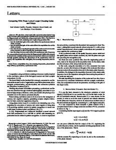
2.1 Maximum Number of MT Estimation To evaluate the performance, we simulated a multiple MT scenario with 6 LSNs located on the hexagon vertex and one LSS in the center, as Fig. 1 depicts. For each LSN, the operating frequency is 2.4 GHz, according to the IEEE 802.11g standard. The coverage area was set to the maximum distance between the LSN and the LSS. The size of data packet used to poll the mobile terminals was fixed to 400 bit and the ACK packet size to 112 bit, according to IEEE 802.11 standard. LSN5
LSN4
LSS
LSN6
LSN1
LSN3
LSN2
Fig. 1. 7 LSN and one LSS grid configuration, 36 m × 32 m.
In order to evaluate the maximum number of users that can be served by an LSS, we observe that time frame necessary to poll a user, to receive back the broadcast packet and then to calculate the user position is:
A. M. VEGNI, A. DI NEPI, A. NERI, C. VEGNI, LOCAL POSITIONING SERVICES ON IEEE 802.11 NETWORKS
T =2
rmax D + DACK + 2TSIFS + LUR c B
(1)
where rmax is the maximum distance served by the LSS [m], c is the speed of light [m/s], TSIFS is the SIFS interval duration, DLUR is the Location Update Request packet size [bit], DACK is the acknowledge packet size [bit], and B is the data rate [Mbps]. Thus, the number of users that the system is able to manage within one super-frame (PCF+DCF) is given by: NTOT =
ΔTPCFmax − TSIFS +
DBEACON + DCF _ END
(2)
B
D ⎛r ⎞ T + ε ⎜ max + LUR + TPIFS ⎟ B ⎝ c ⎠
Maximum number of MT estimation 350
ε= ε= ε= ε=
300
5% 10% 12% 15%
250
200
150
100
where ΔTPCFmax is the maximum duration of the PCF [ms], DBEACON is the BEACON packet size [bit], DCF_END is the CF_END packet size [bit], TPIFS is the PIFS interval duration, and ε is the performance reduction factor due to the coverage area and channel noise. Combining Eq. (1) and (2), the maximum number of users the network is able to manage is: NTOT =
sents the maximum value of MTs that an IEEE 802.11 network can serve.
Numer of MTs
44
ΔTPOLL 1 ΔTSUPERFRAME ℑ ( N )
(3)
where ΔTPOLL is the polling period of the same MT, ΔTSUPERFRAME is the super-frame duration, and ℑ(N) is the integer part of N. As stated previously, NTOT is strictly related to the LUR time and hence to the mobility class of the users, (i.e. for low speed users (1−2 m/s), a good compromise for the LUR rate is 500 ms). According to IEEE 802.11 standard, in our simulation we set the following parameters: SIFS
28 μs
PIFS
48 μs
DIFS
68 μs
Minimum Contention Window period
16 μs
Maximum Contention Window period
4080 μs
Super-frame duration
5 ms
MTs speed magnitude
2 m/s
LUR period
0.5 s
Tab. 1. List of simulation parameter values.
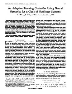
The data rate range spans from 6 Mbps to 26 Mbps, while the LSN coverage area was fixed to the maximum value specified by the IEEE 802.11 standard, for the specific data rate in indoor environment. For each case different paths have been simulated, varying the MT initial position and motion direction, in order to consider the statistics of at least 1000 different points of the grid. Fig. 2 shows the maximum number of MT the algorithm can estimate, for different values of data rate and the performance reduction factor ε. Above 24 Mbit/s and for ε = 15%, the maximum number of MTs is 250, that repre-
50
0
5
10
15
20
25 30 35 Data rate [Mbit/s]
40
45
50
55
Fig. 2. Maximum number of MT estimated, for different values of data rates and performance reduction factor ε.
2.2 Simulation Scenario By considering an hexagonal grid, where multiple MTs moves at 2 m/s, we evaluated algorithm performances in terms of: 1. LSS waiting time, necessary to perform position estimation. This parameter is calculated from the moment the LSS queries the MT to the time it receives back the LSN estimations, (Fig. 5); 2. average number of available and actually used LSNs in the MT covered area, (Fig. 6).; 3. location probability, that expresses the probability the LSS has at least three distance estimations on which to perform the triangulation, (Fig. 7). From a geometrical point of view, triangulation realizes the case of finding the point of intersection of three circles or spheres, for the 2D or 3D case, respectively. In both cases, the centers represent the coordinates of reference nodes, (i.e. LSN1, LSN2.and LSN3). In 2D, this means to find the solution to a set of quadratic equations, such as the following:
( x − xi ) + ( y − yi ) 2
2
= di 2
(4)
where (x, y) is the estimated position of the MT, and (xi, yi) are the coordinates of i-th LSN and di the estimated distance between the MT and i-th LSN. So, the MT position is determined on the basis of the intersection of the distance circles, also called as LSN ranges. Two range measurements provide an ambiguous fix, while three measurements determine a unique position for MT, as represented in Fig. 1(a) and (b), respectively. The same principle is used by GPS, by considering spheres as circles, and the fourth measurement to solve the receiver-clock bias for a 3Dsolution.
RADIOENGINEERING, VOL. 17, NO. 2, JUNE 2008
45
while the number of traceable MT drops to 12 for LSN coverage area less than 25 m.
LSN 2
Finally, in Fig. 7 the number of used LSNs is depicted. It decreases since the LSNs have to send longer packet (containing more TOA estimations) during the DCF phase, causing an additional increase in the number of collisions.
LSN 2
MT
LSN 1
LSN 1 LSN 3
(a)
(b)
Fig. 3. TOA position estimation method. (a) Ambiguous measurement for just two range measurements. (b) Three measurements determine a unique position for MT.
Location Probability
1,000
0,900
0,800
0,700
Location error area
LSN 2
DR=6 Mbps, R=40 m DR=18 Mbps, R=35 m
0,600
DR=24 Mbps, R=30 m DR=36 Mbps, R=25 m
MT
0,500
LSN 1
1
5
9
13
17
21
25
Number of MTs LSN 3
Fig. 6. Location Probability for the multiple MT case. Number of tracked MTs
D
R
Fig. 4. TOA timing errors. Location error area represents the uncertain region for MT position.
40
35 m
18 Mbps
23
30 m
24 Mbps
All the performance results are evaluated as functions of the number of MTs, and for different data rate (D) and coverage area (R) values. In Fig. 5, the LSS Waiting Time increases as soon as the number of MTs increases. The main cause for that is the number of collisions increasing. The LSS Waiting Time is always under 4.5 ms, even on a very crowdie network, allowing the reception of the position estimation in the same super-frame period (5 ms) of the request. In the worst case, considering a delay of 4.5 ms, from the LUR moment to the reception of the position estimation, the terminal has been shift of few cm introducing an error less than 1% (for each LUR the MN has been shifted of 1 m).
12
25 m
36 Mbps
3
20 m
48 Mbps
ms
3,600
6,000 5,000 4,000 3,000
D=6 Mbps, R=40 m
2,000
D=6 Mbps, R=40 m D=18 Mbps, R=35 m D=24 Mbps, R=30 m D=36 Mbps, R=25 m
4,200
Number of used LSNs 7,000
D=18 Mbps, R=35 m
LSSWaiting Time
4,800
Tab. 2. Number of traceable MTs, for an average Location Probability of 80%, and for different values of D and R.
D=24 Mbps, R=30 m D=36 Mbps, R=25 m
1,000 1
5
9
13
17
21
25
Number of MTs
3,000
Fig. 7. Number of used LSNs for the multiple MT case.
2,400 1,800
3. Wireless Microstrip Antennas
1,200 0,600 0,000 1
5
9
13
17
21
25
Number of MTs
Fig. 5. LSS waiting time vs number of MTs.
Fig. 6 shows the MT location probability. To achieve better performance it is more important to have a higher coverage area rather than a higher data rate. Simulations results are shown in Tab. 2. With an average Location Probability of 80%, the LSS receives at least three distance estimation of the 25 MTs for a LSN coverage area greater than 25 m,
In this Section an innovative antenna configuration for “indoor” use and the consequent realized “bread-board” model are shown. Although the initial microstrip antenna designs involving single patches had narrow impedance bandwidths, low polarization purity, poor power handling capabilities, and spurious feed radiation, several new configurations have been proposed to offset these limitations. Mobile communications demand numerous types of antennas with multi-band, agile polarization, agile beam control, in-built diversity capabilities, and compatibility
46
A. M. VEGNI, A. DI NEPI, A. NERI, C. VEGNI, LOCAL POSITIONING SERVICES ON IEEE 802.11 NETWORKS
with EMC. Then, static in-building wireless systems promise equal massive demands for “smart” user-friendly antennas. A narrow bandwidth is a disadvantage of microstrip antennas. For wireless communication systems, the required operating bandwidths are about 7.6% for GSM, (890−960 MHz), 9.5% for DCS, (1710−1880 MHz), and 12.2% for UMTS, (1920−2170 MHz). To meet these bandwidth requirements, many bandwidth-enhancement or broadband techniques for microstrip antennas have been reported recently [12]. Dual-polarized operation has been an important subject in microstrip antenna design and finds application in wireless communication systems that require frequency reuse or polarization diversity. Microstrip antennas capable of performing dual-polarized operation can combat multipath effects in wireless communications and enhance system performance [12]. Compact microstrip antennas capable of dual-polarized radiation are very suitable for applications in wireless communication systems that demand frequency reuse or polarization diversity. Then, dual-frequency microstrip array can find applications in base-station antenna designs for wireless communications since it can have a narrower beam-width radiation pattern in the elevation direction and a broadside radiation pattern with a wide beam-width in the azimuthal direction.
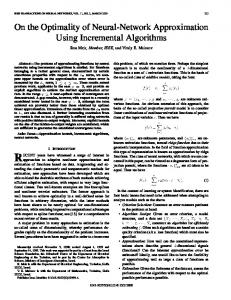
Antenna gain level is 12 dBi at centre frequency (fixed beam). The radiation pattern beam-width radiation is narrow [−10°; +10°] in the elevation plane and wide in the azimuth [−45°;+ 45°] plane. The side lobe level is less than −12 dB. Mutual coupling level is less than −20 dB between two adjacent patches, −30 dB for not adjacent elements. The antenna is also low cost, and easy to be fabricated and microstrip technology ensures a lightweight and easeto-integrate with other circuitry. Cost and fabrication, repeatability and integration with other components are easy issues, as requested for indoor use. Finally, the adopted Kevlar material assures light weight and contained losses. For the above reported performances this microstrip antenna is more than an adequate candidate for IEEE 802.11 applications.
Fig. 8. Microstrip antenna array, 5cm x 18cm x 2cm.
3.1 LSN and LSS Antennas In Fig. 8 a possible candidate for LSN and LSS antenna is shown. Antenna electrical design has been performed by commercial electromagnetic 3D software. Antenna has been tested by HP 8510 Network analyzer for the s-parameters, and by anechoic chamber for the radiation pattern and polarization purity. The antenna is designed to work at 5.0 GHz in broadband mode in RHCP; however, by a proper dimensioning of the slots, resonating frequencies can be steered, so the antenna can work in dual frequency mode [12]. Respect to a “standard” patch antenna the proposed single element appears more compact (effect of the slots on the resonating frequencies). Antenna is matched on the wireless operating frequencies and the percentage is more than 8% (1:1.5 VSWR) considering f = 5.0 GHz as the center frequency. The polarization purity is less than −25 dB at boresight, −20 dB at the edge of coverage [−15°; +15°]. This low value of crosspolarization is achieved by the use of the “sequential rotation” technique, as it can be observed in Fig. 8. In order to have a precise control of amplitude and phase of every element excitation coefficients, hybrid couplers and Wilkinson dividers have been adopted. They assure low coupling levels between branch outputs preventing any undesired reflection due to eventual single element malfunction/mismatching.
4. Conclusion Our aim is to complement WLAN networks with location services for indoor environment. In the first part of the paper, an innovative technique for localization purpose in IEEE 802.11 networks was investigated. Simulation results show the algorithm is able to locate all the users with low mobility. Then, in the second part of the paper we present a design of microstrip antenna for LSN and LSS nodes. The location algorithm and the tracking model for user position are going to be validated by proper test campaign (“proof of concept”) whose scenarios definition is in progress. In this frame, LSN and LSS antennas configuration has been identified and tested. Future works will also implement the localization algorithm in WiMax networks and best performances are attempted for outdoor or open indoor environments, (i.e. airports, train stations, museums, etc.).
References [1] XUE, Y., LI, B., NAHRSTEDT, K. A Scalable Location Management Scheme in Mobile Ad-hoc Networks. In Proceeding of the 26th IEEE Annual Conference on Local Computer Networks 1, Tampa (Florida), 2001, p.102–111. [2] KÜPPER, A. Location-Based Services: Fundamentals and Operation. Hoboken: John Wiley & Sons, 2005.
RADIOENGINEERING, VOL. 17, NO. 2, JUNE 2008
47
[3] VENKATRAMAN, S., CAFFERY JR., J. Hybrid TOA/AOA techniques for mobile location in non-line-of-sight environments. In Proceeding of IEEE Wireless Communications and Networking Conference, WCNC 2004. Atlanta (Ga, USA), 2004, vol. 1, p. 274 to 278.
2001. His research activity has mainly been focused on information theory, signal theory, and signal and image processing and their applications to both telecommunications systems and remote sensing.
[4] BORKOWSKI, J., LEMPIÄINEN, J. Practical network-based techniques for mobile positioning in UMTS. EURASIP Journal on Applied Signal Processing, 2006, article ID 12930, 15 pages.
Prof. Neri is also a member of the Managing Committee of CNIT (National Inter-University Consortium for Telecommunications), a non-profit Consortium currently linking 33 Italian Universities, whose main purpose is to foster research activity and provide networking support to specific projects in the area of telecommunications.
[5] SOLIMAN, S. S., WHEATLEY, C. E. Geolocation technologies and applications for third generation wireless. Wireless Communications and Mobile Computing, 2002, vol. 2, no. 3, p. 229–251. [6] HERSCOVICI, N. New Considerations in the Design of Microstrip Antennas. IEEE Trans. on Antennas and Propagation, 1998, vol. 46, no. 6, p. 807–812. [7] HATAMI, A., PAHLAVAN, K. Performance comparison of RSS and TOA indoor geolocation based on UWB measurement of channel characteristics. In Proceeding of 17th IEEE International Symposium on Personal, Indoor and Mobile Radio Communications, PIMRC 2006, Helsinki (Finland), September 2006, p. 1–6. [8] IBRAHEEM, I. A., SCHOEBEL, J. Time of arrival prediction for WLAN systems using prony algorithm. In Proceeding of the 4th Workshop on Positioning, Navigation and Communication, WPNC 2007. Hannover (Germany), March 2007, p. 29–32. [9] IEEE 802.11 Standard, Supplement to IEEE Standard for Information technology: High-speed Physical Layer in the 5 GHz Band, 1999. [10] IEEE 802.11 Standard, Supplement to IEEE Standard for Information technology: Further Higher Data Rate Extension in the 2.4 GHz Band, 2003. [11] IEEE 802.11 Standard, Wireless LAN Medium Access Control (MAC) and Physical Layer (PHY) Specifications, 1999. [12] WONG, K. L. Compact and Broadband Microstrip Antennas. John Wiley & Sons, Inc. (New York), 2002.
About Authors… Alessandro NERI is full professor in Telecommunications. In 1977 he received the Doctoral Degree in Electronic Engineering from the University of Rome “La Sapienza”. In 1978 he joined the Research and Development Department of Contraves Italiana S.p.A. where he gained a specific expertise in the field of radar signal processing and in applied detection and estimation theory, becoming the chief of the advanced systems group. In 1987 he joined the INFOCOM Department of the University of Rome “La Sapienza” as Associate Professor in Signal and Information Theory. In November 1992 he joined the Electronic Engineering Department of the University of Roma TRE as Associate Professor in Electrical Communications, and became full professor in Telecommunications in September
Anna Maria VEGNI received the 1st level Laurea Degree cum laude in Electronics Engineering from the University of Roma TRE, Rome, Italy, in July 2004. Then, in July 2006, she received the 2nd level Laurea Degree (Laurea Magistralis) cum laude in Electronics Engineering, Telecommunication field, from the University of Roma TRE. Since November 2006, she is a Ph.D. student in biomedical engineering, electromagnetics and telecommunications at the University of Roma TRE. Her main research interests are indoor localization techniques, telecommunication systems, quality-of-service (QoS) and internetworking. Claudio VEGNI received his Laurea Degree cum laude in Electronics Engineering from the University of Roma TRE, Rome, Italy, in July 1998. The thesis is on planar antennas for Satellite applications topic, “Array antenna in suspended technology”, developed in collaboration with Alenia Spazio. In 2003 he joined “Galileo Industries – Rome site”, with the role of supporting Galileo DesignDevelopment and Validation Manager. From June 2004, he joined “Galileo Industries – Munich site” with the task to work on Verification area for GSTBv2 (GIOVE-B) Satellite. On March 2006, he joined AAS-I Navigation Department “SI&V (Galileo System Integration and Verification)” group where he was been acting as Space Segment Verification Responsible in AIV (Assembly Integration and Verification) Monitoring area. In 2007 he attended the Navigation Department “Galileo Test Range” group where he was involved in System design and Test activities in the frame of Galileo project verification. In September 2007, he is TAS-I technical responsible for “EGNOS 2nd Generation Payload Feasibility study”, and in January 2008 he supports ESA in the area of Galileo SAR system. Now, he is a Navigation System Engineer by Thales Alenia Space Italy company (Navigation & Integrated Comunication Business Unit) in the frame of the Navigation Satellite projects.