hard drive and editing capabilities. Because digital video ... A WZD video stream is broken into groups of pictures ... Each stripe is then broken into 8-line by 32- ...
Copyright 2000 NCTA, Technical Program of the Cable 2K Conference , Cable 2K, New Orleans, May 2000.
Low Complexity Real-time Video Encoding for Soft Set-Top Box Platforms Krasimir Kolarov, Feei Chung, William Lynch Interval Research Corporation a broadcasting model in mind, MPEG is asymmetric, with the encoding significantly more complex and costly than decoding.
Abstract This paper presents a very low-complexity wavelet-based video codec, the Wavelet ZCodec (WZD), implemented in real-time on a programmable media chip, the Media Accelerated Processor (MAP-1000). The WZD algorithm is carefully designed to require only adds and shifts. Temporal wavelet transforms are used in place of motion estimation and compensation. With block processing and intermediate coding, WZD is 15 to 20 times less complex than MPEG2. An entire encoder requires only 50K gates and 128KB of memory and can be implemented for a couple of dollars as a chip macro. Experimental results have shown that it achieves similar performance to MPEG2 for typical bitrates and content.
1. INTRODUCTION The fast development of broadband technology brings video capabilities to everyday consumers. The next generation settop boxes (STBs) will allow us to receive, store and manipulate large amounts of video and audio information. Those boxes will have a hard drive and editing capabilities. Because digital video is very resource consuming (an uncompressed 2 hour video can take as much as 216 GB of memory), there is a strong need for encoding capabilities in the box. MPEG, the current standard approach, is very expensive for consumer set-top box encoding applications and does not allow for easy editing. Having been explicitly designed with
Having in mind low cost, easy to time-shift and edit, soft set-top box applications, we have designed a wavelet-based technology WZD (Wavelet Z-coDec) for quality compression of full size (D1) video. Our approach uses wavelet transformations (as opposed to the discrete cosine transform DCT in MPEG) in both the spatial and temporal direction. Thus we avoid the complex and expensive process of motion estimation and motion compensation. The overall algorithm is 15 to 20 times less complex than the MPEG approach and achieves similar or better performance for all important bitrates. WZD is a symmetric codec with very low Mips overhead and low latency encoding (< 6 frames). We require very low power operation and allow cheap color conversion and direct compression of the composite NTSC (our compression technology also decodes chroma from the carrier – see www.interval.com/wzd ). The main implementation benefits are: simplified processing, reduced hardware & software overhead and saved memory and memory bandwidth. They result from our wavelet compression, multiplierless coefficients, block by block processing and intermediate compression. Our solution is ideally suited for real-time processing of analog video sources for a variety of embedded applications - set-top boxes, PVRs (personal video recorders), home networks, cameras and camcorders, security applications.
We will present the WZD algorithm in the next section, followed by a section on the MAP-1000 processor. Experimental results will be shown next, and finally we will conclude with a summary. 2. WAVELET Z-CODEC An image transform codec (compression/ decompression algorithm) generally consists of three basic steps in the forward (compression) direction: 1) forward transform, 2) quantization, 3) entropy coding. The decompression direction consists of an entropy decoding stage followed by the reverse transform. The forward and inverse transforms are exact inverses of each other and are thus lossless. They are often linear, and are performed to decorrelate pixel values so that the resulting coefficients can be better compressed. The quantization stage is lossy, where less important visual information is discarded. The entropy coding stage is again lossless, where the quantized coefficients are encoded into compressed bitstreams. A lossless compression is achieved by omitting the quantization stage. The Wavelet Z-codec follows these same basic steps, using a three-dimensional wavelet transform in the transform stage. Optional intermediate quantization and coding stages may be added to greatly reduce RAM. The basic process flow in the forward direction is: 1) forward transform: 1-a) spatial transform, with TS (2-6) wavelet filters, 1-b) intermediate quantization (optional), 1-c) intermediate entropy encode (optional), 1-d) intermediate decode (optional),
1-e) temporal transform, with HaarHaar wavelet filters, 2) final quantization, 3) final entropy encode. Steps 1-b, c and d are optional, depending on implementation platform. If used, the memory required is significantly reduced and the entire coder including memory can be implemented on a fraction of a chip. As is typical of DCT transform codecs, the processing steps are not applied to entire video frames. Instead, each video field is divided into blocks, where each block is processed separately. The definition of a block as well as details of each of the non-optional processing steps are described in the sections below. 2.1 Processing ‘Units’ – GOPs, Stripes, Blocks, Sticks and Stones A WZD video stream is broken into groups of pictures (GOP) of a fixed number of frames (two), each consisting of two (2) fields. Each GOP is processed independently of each other GOP. We have found that for WZD this GOP length makes a suitable tradeoff between picture quality, bit rate, and complexity. In addition, this short GOP length is well suited for editing and searching. At any point in the compressed stream you are within one of the desired frame. By contrast, the GOP for MPEG codecs is typically fifteen (15) frames. However different GOP lengths and structures can be used depending on scene content. In any case, motion estimation and compensation are performed independently on each GOP. Even such a simple editing operation as “cutting” from one stream to another is a complex operation for an MPEG stream. For WZD, each field in a GOP is further broken into 8-line stripes, with each stripe processed independently of each other stripe. Each stripe is then broken into 8-line by 32-
column blocks of pixels, each block processed independently of each other block. During the temporal transform four corresponding stripes, one from each field of the GOP, are processed together as a stick. Within each stick, four corresponding blocks, one from each field of the GOP, are processed together as a stone. These processing units are illustrated in Figure 1 and Stripe Block
GOP (2 frames, or 4 fields) Figure 1 – A GOP, a Stripe and a Block
The main advantage of using a small processing unit of an 8 x 32 block, or an 8 x 32 x 4 stone, is that it reduces the memory / data cache size and bandwidth requirements. It also reduces occurrences of costly data cache misses in soft implementations and reduces silicon area requirements in hardware implementations. Block processing does present the potential problem of blocking artifacts due to transform discontinuities across block boundaries. This problem is resolved in WZD by the incorporation of edge filters, as described in the next section. 2.2 Processing Step 1-a, Spatial Transform For the spatial transform, the WZD algorithm uses the TS (Two-Six, or 2-6) wavelet filters, which are quadratically lifted Haar wavelet. The basic equations that transform an input sequence xi , 0 ≤ i < 2N, into half-length low-pass and high-pass sequences fi and hi respectively, 0 ≤ i < N, are: 2-6 Forward Transform: fi = x2i + x2i + 1
(1)
gi = x2i – x2i + 1
(2)
hi = gi – floor{( fi – 1 – f i + 1 ) / 8}
(3)
2-6 Inverse Transform: gi = hi + floor{( fi – 1 – f i + 1 ) / 8}
(4)
x2i = ( fi + gi ) / 2
(5)
x2i + 1 = ( fi – gi ) / 2
(6)
Equations 1, 2 (and 5, 6 in the inverse direction) form the simple Haar transform, and Equations 3 and 4 perform the “lifting” method [3], which is in essence a quadratic interpolation. Equations 3 and 4 cannot be used at the two edges of the sequence and different filters are required. To minimize blocking artifacts, we have designed special edge filters that ensure polynomial continuity across block boundaries. These filters effectively result in constant, linear or quadratic interpolation for input sequences of length 2 (N = 1), 4 (N = 2) or ≥ 6 (N ≥ 3) respectively. Quadratic interpolants typically account for 98% of the variation at a point. The equations for the case N = 1 (replacing Equations 3 and 4) are, for i = 0: Forward: h0 = g0 .
(3b)
Inverse: g0 = h0 .
(4b)
For N = 2, the equations are, for i = 0, 1: Forward: hi = gi – floor{ ( f0 – f 1 ) / 4} . Inverse: gi = hi + floor{ ( f0 – f 1 ) / 4}.
For N ≥ 3, the equations are: Left Edge (i = 0): h0 = g0 – floor{ ( 3f0 – 4f1 + f2 ) / 8 } g0 = h0 + floor{ ( 3f0 – 4f1 + f2 ) / 8 } . Right Edge (i = N-1): hN-1 = g N-1 – floor{ ( fN-3 – 4fN-2 + 3fN-1 ) / 8 } g N-1 = h N-1 + floor{ (fN-3 – 4fN-2 + 3fN-1 ) / 8 } .
Note that all filters above map integers to integers and are reversible. They are linear except for the floor operations. They are also short, and use dyadic rational coefficients (i.e.,
they are integers divided by powers of two) with small numerators. Thus, the entire WZD transform can be implemented with only adds and fixed shifts; no multiplies or variable shifts are required. Note also that all filters above are onedimensional, but they can be applied to the horizontal or vertical direction. In the horizontal direction each application partitions its input sequence into left (L) and right (R) ‘subbands’, where the left subband holds the low-pass (or average) result sequence f and the right subband holds the high-pass (or vertical edge details) result sequence h. In the vertical direction each application partitions its input sequence into top (T) and bottom (B) subbands, where the top subband holds the low-pass (again, average) results f and the bottom subband holds the high-pass (or horizontal edge details) results h. For each 32column by 8-line block of input image pixel luma component data, the wavelet filters are applied in both horizontal and vertical directions several times successively to form the final wavelet pyramid in Figure 2. LLTTR LRT LLTBL LLTBR R LLB
LRB
Figure 2 – Wavelet pyramid for luma; 0 = LLTTLLTL, 1 = LLTTLLTR, 2 = LLTTLRT, 3 = LLTTLLB, 4 = LLTTLRB
Each block of the chroma components in component video is half as wide as luma (16 columns by 8 lines) because the data is subsampled in the horizontal direction. Thus, one fewer horizontal transform is performed. Figure 3 shows the resulting wavelet pyramid.
LTTR RT LTBL
LTBR
LB
RB
Figure 3 – Wavelet Pyramid for chroma; 0 = LTTLLTL, 1 = LTTLLTR, 2 = LTTLRT, 3 = LTTLLB, 4 = LTTLRB Note that at the end of the spatial transform, subband 0 contains the average value of all pixels in the block. Thus, subband 0 from all blocks form a ‘thumbnail’ image of the original. Other subbands contain more edge sharpness information, and we expect their coefficients to be small or zero except at very sharp edges. In fact, due to the smoothness nature of typical video data, we expect the R, RT, LB and RB subbands to be mostly zero. Furthermore, many small values in the LRT, LLB and LRB subbands can be quantized to zero without much visual loss. 2.3 Processing Transform
Step
1-e,
Temporal
A Haar-Haar wavelet transform is used in the temporal domain for increased compression. The equations used, i.e., the Haar filters, are shown below. They are simply Equations 1, 2 and 3b in the forward direction, and Equations 4b, 5 and 6 in the inverse direction. Forward Temporal Transform: fi = x2i + x2i + 1 hi = gi = x2i – x2i + 1
(1) (2), (3)
Inverse Temporal Transform: x2i = ( fi + hi ) / 2 x2i + 1 = ( fi – hi ) / 2 .
(4b), (5) (4b), (6)
The filters are applied to every pixel in each stone, taking as input the four values from the four fields at the same pixel location, as illustrated in Figure 4.
Frame 1, Field 1 Stone Frame 1, Field 2 Block k Frame 2, Field 1 Block k Frame 2, Field 2 Block k Block k x0
x1
x2
x3
Figure 4 - Temporal transform input sequence construction example
For each pixel, i.e., for each input sequence, the filters are applied twice (hence Haar-Haar), yielding the subbands Slow-Slow, Slow-Fast, Fast-Slow and Fast-Fast. As with the spatial transform filters, the temporal transform filters can be implemented with adds and fixed shifts only. The temporal transform is much lower in complexity than the motion estimation and motion compensation done in MPEG. Furthermore, it operates on a GOP of two frames, as compared to a typical GOP of fifteen frames for MPEG, thus making it easier to navigate compressed video streams, facilitating video manipulations such as editing and searching. The short GOP does imply that when there is significant motion in a video sequence such as a sports footage, we expect our WZD algorithm to perform worse than MPEG. However, for most sequences including movies, WZD yields results comparable to MPEG. 2.4 Processing Step 2, Quantization The WZD quantization strategy is based on the well-known idea of discarding information that the human visual system (HVS) is unable to perceive under expected viewing conditions. This imperceptible (and unusable) information primarily consists of contrast resolution at high spatial frequencies. Such information is imperceptible due to optical losses (diffraction and chromatic aberration) in the HVS.
Quantization is traditionally performed by dividing a coefficient by a value Q, Q dependent on the spatial frequency of the coefficient. WZD simplifies this operation by restricting Q to be a power of two (Q = 2q) so that quantization is implemented simply by means of discarding the rightmost bits of those coefficients, i.e., shifting the coefficients by q bits. Processing step 1-b, if performed, would be done in a similar manner so that only shifting would be used rather than division. 2.5 Processing Step 3, Entropy Coding The wavelet pyramid, after being quantized, will have substantial runs of zeros as well as substantial runs of non-zeros, which makes it natural to code the coefficients into two streams, one being a stream of significance bits, and the other being a stream of non-zero coefficients. There is one significance-bit for each coefficient, a one if the quantized coefficient is non-zero and a zero if the quantized coefficient is zero. In addition to having substantial runs of zeros, the significance bits are also highly correlated, where each significance bit is most likely the same as the preceding significance bit. Arithmetic coders are known to compress streams such as the significance stream very well. We use a modification of the low complexity, binary arithmetic coder known as the Z-coder. We have found that, for video, the Z-coder calculations can be done with 8 bits of precision and that only 3 bits of context (3 previous significance bits) give a good prediction of the next bit. These three bits of context imply a 23 entry table of 8-bit increments. Details of the Z-coder can be found in [2]. The non-zero coefficients are encoded using a Huffman coder. For each coefficient, the codeword is obtained for its absolute value and merged into the code stream, followed by the
sign bit. The Huffman coder has been thoroughly studied in academics and industry, and will not be described here. For details, on the Huffman and arithmetic coders refer to [6]. As with the transform filters, we designed the Z-coder and the Huffman coder to require only adds and shifts to maintain lowcomplexity in implementation. 3. THE MAP 1000 PROCESSOR AND ARCHITECTURE Equator Technologies’ MAP (Media Accelerated Processor) 1000 is a low-cost programmable processor designed to handle the large computational demands of digital media processing, including image and video codec, 2D and 3D graphics, as well as digital audio codec, synthesis and spatialization. It provides a flexible, high-performance environment for developing real-time multimedia applications, many of which have rapidly evolving functional requirements due to the recent growing need for multi-function digital TV and STBs. 3.1 The Map Architecture The MAP 1000 has a high computation rate because it is based on an on-chip parallelism technique known as Very Long Instruction Word (VLIW) architecture. VLIW is one of two well-established schools of thoughts on how a high degree of instruction-level parallelism can be achieved, the other being the super-scalar architecture. Today’s popular microprocessors such as the Pentium II are based on the super-scalar approach, which require special on-chip hardware to look through the instruction stream and find independent operations which can be executed simultaneously by multiple execution units available so that parallelism can be maximized. This special hardware typically takes up a significant portion of the chip’s die area. Each instruction in superscalar processors codes for only one single operation, and the grouping
and scheduling of instructions for execution is done at execution time in hardware. On the other hand, for VLIW processors the difficult task of finding parallelism is moved to the compiler. The compiler searches for eligible operations, checks for data dependencies, controls resource conflicts, and packages these operations into VLIW instruction words. Thus, each instruction word explicitly describes the parallelism by specifying which operation is to be performed by each execution unit during each cycle. Because VLIW processors do not require special on-chip hardware, they can be much cheaper than superscalar processors, but they require sophisticated compilers to perform the instruction-level parallelism properly. 3.2 The MAP compiler The Equator MAP compiler is critical in ensuring that the computational power and architectural features of the MAP 1000 are fully utilized. It supports a wide range of optimizations, including software pipelining, preconditioning, as well as trace scheduling which can search a whole routine for eligible operations. It can also explore across natural code boundaries such as branches for opportunities of increased parallelism far beyond the limited search window seen in existing super-scalar architectures. The MAP core processor is programmable in C, and the MAP C compiler is generally compliant with ANSI standard C. It supports a media intrinsic API with a large suite of 32-bit and 64-bit integer and floating-point scalar operations, partitioned operations with 64-bit registers, plus operations with 128-bit partitioned long constant/variable that facilitate vector arithmetic. With extensive use of partitioned media intrinsic, the implementation of the WZD wavelet transforms on the MAP core processor requires only three (3) cycles per coefficient.
3.3 MAP Coprocessors The MAP-1000 has several functional units in addition to the VLIW media core processor. The Data Streamer intelligently handles interand intra-chip data transfers as well as hides the penalty due to data cache misses. It can be programmed to transfer data of various shapes and forms. The Data Streamer executes commands in a separate thread of control with minimal CPU support. Thus, conventional double-buffering schemes can be used to fully overlap data movement and VLIW core or Variable Length Encoder/Decoder (VLx) processing. Another functional unit is the Fixed Function Block, which includes graphics accelerators, a video scalar and the VLx. The VLx is actually programmable, currently in assembly. It is a RISC coprocessor which can be used to perform bit-sequential tasks that are not well suited for the VLIW core. The VLx contains special-purpose hardware, called the GetBits engine, for bitstream processing and hardware accelerated MPEG2 table lookup. More details on the MAP platform can be found in [1] as well as at ETI’s web page http://www.equator.com .
stone, with resulting wavelet coefficients placed into contiguous memory locations in SDRAM. Again double-buffering of the coefficients buffer is done so that the coefficients from the current stone can be transferred to the VLx while those from the next stone are calculated. The Data Streamer transfers the wavelet coefficients from the SDRAM, stored in its natural order of scan-order, into memory accessible by the VLx called CM1 in subbandorder. Coefficients grouped in subband-order are expected to have longer runs of zeros or non-zeros than in scan-order and are thus expected to yield a smaller Z-coder codestream. The final quantization and final coding stages are implemented in the VLx core. The data streamer and the GetBits engine are used to transfer the resulting codestream bits back to SDRAM. The core then writes the codestreams out to file. The inverse direction of the WZD is implemented in a similar manner. 5. EXPERIMENT RESULTS
4. WZD on MAP
Data in the frame buffer is in fieldinterlaced YuYv 4:2:2 format, thus the Y (luma), U (chroma 1) and V (chroma 2) components are first extracted out into separate buffers in the core. The wavelet transforms for each component are then performed for the
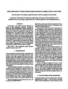
Bug - MPEG2 Head - MPEG2 Chase - MPEG2
46 44 42 PSNR
For the implementation of the forward direction of the WZD algorithm on the MAP1000, the Data Streamer is programmed to transfer pixel values from frame buffers to contiguous memory locations on the on-chip SDRAM one stone at a time. Double-buffering is done so data from the next stone can be transferred in while the current stone is processed.
Bug - WZD Head - WZD Chase - WZD
40 38 36 34 32 30 0.2
0.4
0.6
0.8 bits per pixel
1.0
1.2
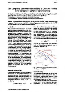
Figure 5 - Rate-Distortion curve comparison of WZD software implementation vs. MPEG2 Figure 5 plots the quantitative results of a software implementation of the WZD codec, compared to those of a standard software implementation of MPEG2, Test Module 5 (TM5). 3 footages were processed, each 300
frames long. “Bug” is a footage from an animated movie, “Head” is a talking-head footage from a motion movie and “Chase” is a motorcycle chase footage from the same movie. The curves are known as rate-distortion curves. Here the distortion is represented by the Peak Signal to Noise Ratio (PSNR) in dB, actually the opposite of distortion, and the rate is represented by the bit rate of the compressed bitsteam in bits per pixel (bpp). For full-size frames, 1 bpp corresponds to roughly 10 Mbps (million bits per second). Although PSNR may not always be an accurate indication of the visual quality of a moving sequence, typically the higher the PSNR, the better the quality. Figure 5 shows that WZD yielded better quality than MPEG2 for two of the three sequences. Furthermore, WZD quality degrades smoothly as the bitrate is reduced, where as MPEG2 quality drops off sharply below 0.3 bpp. Figures 6 and 7 show sample results of the WZD algorithm implemented on the Equator MAP-1000, intermixed with results of TM5, the standard software MPEG2 implementation. The image quality can be seen to degrade as the bitrate is reduced, and WZD results are comparable to TM5 results at most bitrates. At low bitrates WZD results are generally better. For example, in Figure 7, WZD at 1.8 Mb/s is visibly better than TM5 at similar rate. 6. SUMMARY In this paper we have described a soft realtime implementation of the Wavelet Z-coDec or WZD, a very-low complexity wavelet-based video codec, on the MAP-1000. WZD was designed specifically with low cost, ease of compressed video stream manipulation and soft set-top box applications in mind. The MAP-1000, with its powerful VLIW architecture, compiler and supporting coprocessors, enables this soft implementation of the WZD to be in real-time. Combining the WZD with MAP-1000 allows timely response
to rapid changes in market demand and industry standards. WZD is far less complex than MPEG-2, and experiment results show that it yields comparable quality to MPEG-2 in general. In addition to the implementation of the WZD technology on the Equator MAP-1000, we have also built a software implementation on the Pentium PC as well as another popular media processor – the Philips TriMedia. Some of the advantages of our approach come to life in a hardware implementation, i.e. an ASIC or part of an ASIC (system-on-a-chip). Because the entire algorithm can be implemented with shifts and adds only, we anticipate to be able to design a full encoder with 50 – 60,000 gates, significantly less than MPEG-2 encoders with comparable quality. For more details on such implementations, please refer to [4] and [5], which together with several other papers and descriptions can be found at http://www.interval.com/wzd. Acknowledgements Many thanks to Equator Technologies, Inc., which has provided wonderful technical support, and to Bill Arrighi, who has made important contributions towards implementing the WZD on the MAP-1000 as well. References [1] C. Basoglu, K. Zhao, K. Kojima and A. Kawaguchi, The MAP-CA VLIW-based Media Processor from Equator Technologies inc. and Hitachi Ltd., White Paper ETI, January 2000. [2] L. Bottou, P. G. Howard, and Y. Bengio, The Z-Coder Adaptive Coder, Proceedings of the Data Compression Conference, pp. 13-22, Snowbird, Utah, March 1998. [3] K. Kolarov and W. Lynch, Compression of Functions Defined on Surfaces of 3D Objects, In J. Storer and M. Cohn, editors, Proc. Of Data Compression Conference, IEEE Computer Society Press, 1997.
[4] K. Kolarov and W. Lynch, “Very Low Cost Video Wavelet Codec,” SPIE Conference on Applications of Digital Image Processing, Vol. 3808, Denver, July 1999. [5] W. Lynch, K. Kolarov and B. Arrighi, “Low Cost Video Compression Using Fast, Modified Z-coding of Wavelet Pyramids,” Proc. of the
International Conference on Image Processing ICIP’99, Kobe, October 1999. [6] I. Whitten, R. Neal, and J. Cleary, Arithmetic Coding for Data Compression. Communications of the ACM 30, 6 (June) 1987, pp. 520-541
(a) Original
(b) MPEG2 @ 6 Mb/s
(c) WZD @ 4.5 Mb/s
(d) MPEG2 @ 3.9 Mb/s
(e) WZD @ 2.6 Mb/s
(f) MPEG2 @ 2 Mb/s
Figure 6 – Processing results of MPEG2 and WZD codec algorithms applied to a motorcycle chase sequence. (a) through (f) are ordered in decreasing bitrate.
(a) Original
(b) MPEG2 @ 3.7 Mb/s
(c) WZD @ 3.1 Mb/s
(d) MPEG2 @ 1.8 Mb/s
(e) WZD @ 1.8 Mb/s
(f) WZD @ 1.2 Mb/s
Figure 7 – Processing results of MPEG2 and WZD codec algorithms applied to a talking head sequence. (a) through (f) are ordered in decreasing bitrate.