Qin Zhang, Wei Zhao, Student Member, IEEE, and Alan Seabaugh, Fellow, IEEE. AbstractâA formula is derived, which shows that the sub- threshold swing of ...
IEEE ELECTRON DEVICE LETTERS, VOL. 27, NO. 4, APRIL 2006
297
Low-Subthreshold-Swing Tunnel Transistors Qin Zhang, Wei Zhao, Student Member, IEEE, and Alan Seabaugh, Fellow, IEEE
Abstract—A formula is derived, which shows that the subthreshold swing of field-effect interband tunnel transistors is not limited to 60 mV/dec as in the MOSFET. This formula is consistent with two recent reports of interband tunnel transistors, which show lower than 60-mV/dec subthreshold swings and provides two simple design principles for configuring these transistors. One of these principles suggests placing the gate adjacent to the tunnel junction. Modeling of this configuration verifies that sub-60-mV/dec swing is possible. Index Terms—Silicon-on-insulator (SOI), subthreshold swing, tunnel transistor.
I. I NTRODUCTION
I
N A FIELD-EFFECT transistor (FET), the minimum voltage swing needed to turn a transistor “ON” is an important figure of merit that ultimately sets the minimum power supply voltages and the minimum power dissipation of a technology. The subthreshold swing is defined as the gate voltage required to change the drain current by one order of magnitude, one decade. In the MOSFET, the subthreshold swing is limited to (kT /q) ln10 or 60 mV/dec at room temperature, and with scaling, the subthreshold swing increases [1] (k is Boltzmann’s constant, q is the electron charge, and T is the temperature). This increase in subthreshold swing as gate length is decreased marks a significant fundamental limitation of conventional FETs. In this letter, we show analytically that: 1) certain interband tunnel transistors can have subthreshold swings below 60 mV/dec and 2) that the subthreshold swing is minimized by engineering the transistor geometry to enhance the gate control of the tunnel-junction bias-voltage and internal electric field. In recent years, a growing number of transistors have been reported, which explore the use of the field effect to gate an interband tunneling current [2]–[7]. Several of these authors have characterized the subthreshold swing. In the carbon nanotube field-effect transistor of Appenzeller et al. [5], a subthreshold swing of 40 mV/dec was measured in a doublegated transistor in which interband tunnel current flows through an n-p-n channel modulated by a top gate. In simulations, Bhuwalka et al. [4] have shown in a vertical gated p-i-n Si/SiGe interband tunneling transistor that subthreshold swings of 44 mV/dec can be achieved. In a lateral embodiment of the p-i-n Si interband tunnel transistor, Wang et al. [3] have shown
Manuscript received January 4, 2006. This work was supported by the Office of Naval Research under Contract N00014-02-1-0924. The review of this letter was arranged by Editor E. Sangiorgi. The authors are with the Department of Electrical Engineering, University of Notre Dame, Notre Dame, IN 46556 USA. Digital Object Identifier 10.1109/LED.2006.871855
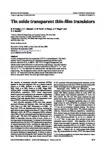
Fig. 1. Silicon tunneling current density versus electric field for a reversejunction bias of 1 V showing the excellent experimental agreement between (1), solid line, and theory measurements (after Taur et al. [10]) using the data of Stork and Isaac [11] and Fair and Wivell [12]. The inset shows the p+ -n+ tunnel-junction energy band diagram under bias Veff .
by simulation that subthreshold swings of 15 mV/dec and even smaller are achievable and conclude that the subthreshold swing is not limited by kT /q. In this letter, we outline the reasons for the low subthreshold swing in tunnel transistors and analyze a new transistor configuration for low subthreshold swing transistor action. II. S UBTHRESHOLD S WING OF T UNNEL T RANSISTORS The subthreshold swing S of a FET is defined by S = ln 10 dVGS /d(ln ID ) [8], where VGS is the transistor gate– source voltage and ID is the drain current. In an interband tunneling transistor, the drain current flows across a degenerately doped p+ -n+ tunnel junction, a transport mechanism that is particularly well described, in the reverse, Zener tunneling direction, by Sze [9] �
b I = aVeff ξ exp − ξ
� (1)
where Veff is the tunnel–junction bias (see the inset of Fig. 1), ξ is the electric field, and a and b are coefficients determined by the materials’ properties of the junction and � the cross-sectional area of the device A. Specifically, a = Aq 3 2m∗ /Eg /4π 2 �2 √ 3/2 and b = 4 m∗ Eg /3q�, where m∗ is the carrier effective mass, Eg is the energy band gap, and � is Planck’s constant divided by 2π. This simple analytic expression for interband tunneling (1) is in phenomenal agreement with the measurements of reverse biased p+ -n+ tunnel junctions [10]–[12]
0741-3106/$20.00 © 2006 IEEE
Authorized licensed use limited to: IEEE Xplore. Downloaded on November 3, 2008 at 15:51 from IEEE Xplore. Restrictions apply.
298
IEEE ELECTRON DEVICE LETTERS, VOL. 27, NO. 4, APRIL 2006
Fig. 2. Schematic cross section of an interband tunnel transistor where the ultrathin Si body is heavily doped to form a p+ -n+ tunnel junction, and the gate is placed over the fully depleted p-side.
spanning eight orders of magnitude in current, as shown in Fig. 1, with effective mass as the sole fitting parameter. The derivative of the tunneling current expression of (1) with respect to the gate–source voltage can be used to determine an expression for the subthreshold swing of a field-effect tunneling transistor. � S = ln 10
1 dVeff ξ + b dξ + 2 Veff dVGS ξ dVGS
�−1 .
(2)
There are two terms in the denominator of (2), which can be maximized in order to achieve a low subthreshold swing, and these terms are not limited by kT /q. According to the first term, the transistor should be engineered so that the gate–source voltage directly controls the tunnel-junction bias Veff ; this suggests a transistor geometry with a thin and/or high-κ gate dielectric and an ultrathin body to assure that the gate field directly modulates the channel. For an equivalent oxide thickness approaching 1 nm, dVeff /dVGS ≈ 1 and the first term in the denominator of (2) is approximately inversely related to VGS . Accordingly, the subthreshold swing in a tunnel transistor increases with gate–source voltage, a characteristic that has been observed in both measurements [5] and simulations [3], [4]. A second way to lower the subthreshold voltage swing is described by the second term in the denominator of (2), which says that the derivative of the junction electric field on the gate–source voltage should be maximized. This is a primary basis for gate control in the interband tunnel transistor of Bhuwalka et al. [4]. In such a device, the gate–source voltage changes the tunneling width and increases the junction electric field. In practice, the tunnel-junction bias and the junction electric field are coupled and cannot be engineered independently. III. L OW S UBTHRESHOLD -S WING D EVICE D ESIGN Using the design guidance of (2), we explore a new transistor geometry toward achieving low subthreshold-swing operation. A schematic cross section of the transistor is shown in Fig. 2 and is comprised of a silicon-on-insulator (SOI) structure in which a lateral p+ -n+ tunnel junction is formed in an ultrathin semiconductor body; a gate is placed on the p-side. The gate is aligned to the junction on the p-side to facilitate control of the p-side electrostatic potential; the p region is fully depleted for zero gate bias. This device geometry is amenable to an analytic solution for the potential profile using a two-dimensional (2-D) Poisson
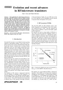
Fig. 3. Energy band diagrams at x = 0 for the Si interband tunneling transistor with (a) zero and (b) negative gate voltages. The simulated gate oxide thickness is 1 nm, the Si layer is 2 nm, the n and p net doping densities are 1020 /cm3 , and the gate length is 20 nm. Note that as the gate–source bias changes by 0.2 V, the electrostatic potential on the p-side shifts by approximately 0.2 V, i.e., dVeff /dVGS ∼ 1. The gray arrows in (b) indicate the ON-state tunneling paths.
equation, a solution method described by Young [13]. This analysis ignores the effects of statistical dopant fluctuations, which will become increasingly important as the transistor dimensions are minimized. On the p-side, the potential φ(x, y) is given by d2 φ(x, y) d2 φ(x, y) qNA + = 2 2 dx dy εSi for
0 ≤ x ≤ tSi
and
0 ≤ y ≤ L (3)
where NA is the acceptor doping concentration on the p-side, εSi is the Si dielectric constant, tSi is the thickness of the Si layer, and L is the gate length. Using a parabolic approximation at low drain-to-source voltage VDS gives φ(x, y) = c0 (y) + c1 (y)x + c2 (y)x2 , where the coefficients c0 , c1 , and c2 are functions of y only. The n-side is unmodulated by the gate and, therefore, can be treated as a one-dimensional (1-D) problem with the potential given by d2 φ(y) qND =− 2 dy εSi
for 0 ≤ x ≤ tSi and L ≤ y ≤ L + W (4)
where ND is the donor doping concentration on the n-side, and W is the depletion length on the n-side. Four boundary conditions are applied: 1) constant potential on the surface between the semiconductor and the gate oxide; 2) zero electric field in the x-direction on the surface between the semiconductor and the buried oxide; 3) continuous potential and electric field at the p-n junction; and 4) 0.3-eV Schottky barrier at the drain contact. Equations (3) and (4) can then be solved to obtain the surface potential and energy band diagrams versus drain–source and gate–source bias. The transistor operation can be understood from the computed energy band diagrams in Fig. 3 for a drain–source bias of
Authorized licensed use limited to: IEEE Xplore. Downloaded on November 3, 2008 at 15:51 from IEEE Xplore. Restrictions apply.
ZHANG et al.: LOW-SUBTHRESHOLD-SWING TUNNEL TRANSISTORS
TABLE I CALCULATED SUBTHRESHOLD SWINGS FOR THE Si INTERBAND TUNNEL TRANSISTOR OF FIG. 2 VERSUS GATE VOLTAGE
299
swing ∼ 7 mV/dec occurs near VGS = 0.07 V, and the low subthreshold swings can be kept within a small gate–source voltage, 40 mV, in reasonable agreement with the results shown in Table I. From Fig. 4, a voltage swing of 140 mV provides an ON -to- OFF current ratio of 103 compared to a MOSFET swing of 180 mV. The voltage swing of 140 mV in the tunnel transistor should be reduced by changing the channel materials to, e.g., Ge or InAs while increasing the current drive. IV. D ISCUSSION Band-to-band Si tunnel transistors have been demonstrated with ON-state current density as high as 100 µA/µm [6], which is below the MOSFET’s 1000 µA/µm (90-nm process node) [14]. Simulations indicate that higher interband current density (850 µA/µm) can be obtained using Ge channels [4]. Tunnel transistors have much lower off leakage, < 0.1 nA/µm [6], than the MOSFET, ∼ 150 nA/µm [15], for the same technology node, 90 nm, due to the high barrier imposed by the p-n junction and resulting in much lower static power dissipation. The low subthreshold swing of the tunnel transistor suggests low power applications; subthreshold logic circuits [16] are of particular relevance to this type of transistor.
Fig. 4. Simulated transfer characteristic of the proposed Si interband tunneling transistor using the Synopsys 2-D simulator.
−0.2 V; these band diagrams correspond to the surface of the SOI at x = 0. The transistor off condition is shown in Fig. 3(a); for a gate–source voltage of zero, the p-side is depleted and the interband tunneling probability is low. When a negative gate voltage is applied, the valence band on the p-side is raised above the Fermi level on the n-side turning the interband tunneling and the transistor ON [Fig. 3(b)]. In this transistor geometry, the gate screens the drain field enabling current saturation and isolation. Using these energy band simulations and this transistor geometry to compute the derivatives in (2), the bias dependence of the subthreshold swing can be estimated, given that b is 33 MV/cm for Si, and Veff and ξ are extracted from the simulated band diagrams [Table I]. The subthreshold swing is dependent on the applied gate–source bias, and it is apparent that this device can achieve smaller than 60 mV/dec over a small bias range near zero gate voltage. For the tunnel transistor, it is clear that the minimum subthreshold swing will not be the most important parameter. Rather, it will be necessary to define the minimum voltage swing needed to achieve a given ON -to- OFF current ratio. The Synopsis device simulator [17] [former Integrated Systems Engineering (ISE)] is used to compute the 2-D energy band and channel electric-field profiles to verify agreement with the analytic model. The computed electric-field distribution is then used with (1) to determine the current distribution in the channel, allowing a comparison with our analytic calculations. The ID −VGS transfer characteristic, for the device geometry previously given, is shown in Fig. 4. The 2-D simulations are in good agreement with the analytic model; low subthreshold
V. C ONCLUSION An analytic expression was derived, which showed that the subthreshold swing of interband tunnel transistors was a function of the gate–source voltage and can beat the MOSFET limit of 60 mV/dec about certain gate biases. Based on this expression, a new SOI tunnel transistor was proposed and simulated, outlining some of the attributes of the low subthreshold swing in interband tunneling transistors. R EFERENCES [1] Q. Chen, B. Agrawal, and J. Meindl, “A comprehensive analytical subthreshold swing (S) model for double-gate MOSFETs,” IEEE Trans. Electron Devices, vol. 49, no. 6, pp. 1086–1090, Jun. 2002. [2] C. Aydin, A. Zaslavsky, S. Luryi, S. Cristoloveanu, D. Mariolle, D. Fraboulet, and S. Deleonibus, “Lateral interband tunneling transistor in silicon-on-insulator,” Appl. Phys. Lett., vol. 84, no. 10, pp. 1780–1782, Mar. 2004. [3] P.-F. Wang, K. Hilsenbeck, T. Nirschl, M. Oswald, C. Stepper, M. Weiss, D. Schmitt-Landsiedel, and W. Hansch, “Complementary tunneling transistor for low power applications,” Solid State Electron., vol. 48, no. 12, pp. 2281–2286, May 2004. [4] K. K. Bhuwalka, J. Schulze, and I. Eisele, “Performance enhancement of vertical tunnel field-effect transistor with SiGe in the δp+ layer,” Jpn. J. Appl. Phys., vol. 43, no. 7A, pp. 4073–4078, Jul. 2004. [5] J. Appenzeller, Y.-M. Lin, J. Knoch, and P. Avouris, “Band-to-band tunneling in carbon nanotube field-effect transistors,” Phys. Rev. Lett., vol. 93, no. 19, pp. 196805-1–196805-4, Nov. 2004. [6] T. Nirschl et al., “The tunneling field-effect transistor (TFET) as an add-on for ultra-low voltage analog and digital processes,” in IEDM Tech. Dig., Dec. 2004, pp. 195–198. [7] K. R. Kim, H. H. Kim, K.-W. Song, J. I. Huh, J. D. Lee, and B.-G. Park, “Field-induced interband tunneling effect transistor (FITET) with negative-differential transconductance and negative-differential conductance,” IEEE Trans. Nanotechnol., vol. 4, no. 3, pp. 317–321, May 2005. [8] S. M. Sze, Physics of Semiconductor Devices, 2nd ed. New York: Wiley, 1981, p. 447. [9] ——, Physics of Semiconductor Devices, 1st ed. New York: Wiley, 1969, p. 111.
Authorized licensed use limited to: IEEE Xplore. Downloaded on November 3, 2008 at 15:51 from IEEE Xplore. Restrictions apply.
300
IEEE ELECTRON DEVICE LETTERS, VOL. 27, NO. 4, APRIL 2006
[10] Y. Taur, C. H. Wann, and D. J. Frank, “25 nm CMOS design considerations,” in IEDM Tech. Dig., Dec. 1998, pp. 789–792. [11] J. M. C. Stork and R. D. Isaac, “Tunneling in base–emitter junctions,” IEEE Trans. Electron Devices, vol. ED-30, no. 11, pp. 1527–1534, Nov. 1983. [12] R. B. Fair and H. W. Wivell, “Zener and avalanche breakdown in As-implanted low-voltage Si n-p junctions,” IEEE Trans. Electron Devices, vol. ED-23, no. 5, pp. 512–518, May 1976. [13] K. K. Young, “Short-channel effect in fully depleted SOI MOSFET’s,” IEEE Trans. Electron Devices, vol. 36, no. 2, pp. 399–402, Feb. 1989.
[14] T. Ghani et al., “A 90 nm high volume manufacturing logic technology featuring novel 45 nm gate length strained silicon CMOS transistors,” in IEDM Tech. Dig., Dec. 2003, pp. 978–980. [15] S. Borkar, “Circuit techniques for subthreshold leakage avoidance, control, and tolerance,” in IEDM Tech. Dig., Dec. 2005, pp. 421–424. [16] H. Soeleman, K. Roy, and B. C. Paul, “Robust subthreshold logic for ultra-low power operation,” IEEE Trans. VLSI Syst., vol. 9, no. 1, pp. 90–99, Feb. 2001. [17] Synopsys TCAD Tool. (2005). [Online]. Available: http://www.synopsys. com/products/tcad/tcad.html
Authorized licensed use limited to: IEEE Xplore. Downloaded on November 3, 2008 at 15:51 from IEEE Xplore. Restrictions apply.