That is to say, it is the processes of examination, not a process of change such as ...... More information related to the NEREUS approach may be found at (Favre, ...
3 MDA-Based Reverse Engineering Liliana Favre
Universidad Nacional del Centro de la Provincia de Buenos Aires Comisión de Investigaciones Científicas de la Provincia de Buenos Aires Argentina 1. Introduction Nowadays, almost companies are facing the problematic of having to modernize or replace their legacy software systems. These old systems have involved the investment of money, time and other resources through the ages. Many of them are still business-critical and there is a high risk in replacing them. Therefore, reverse engineering is one of the major challenges for software engineering today. The most known definition of reverse engineering was given by Chikofsky and Cross (1990): “the process of analyzing a subject system to (i) identify the system’s components and their interrelationships and (ii) create representations of the system in another form or at a higher-level of abstraction”. Reverse engineering is the process of discovering and understanding software artifacts or systems with the objective of extracting information and providing high-level views of them that can be later on manipulated or re-implemented. That is to say, it is the processes of examination, not a process of change such as forward engineering and reengineering. Forward engineering is the traditional process of moving from high-level abstractions and implementation-independent designs to the physical implementation of a system. On the other hand, software reengineering includes a reverse engineering phase in which abstractions of the software artifacts to be reengineered are built, and a forward engineering phase that moves from abstractions to implementations (Sommerville, 2004) (Canfora &Di Penta, 2007). Reverse Engineering is also related with software evolution and maintenance. Software evolution is the process of initial development of a software artifact, followed by its maintenance. The ANSI/IEEE standard 729-1983 (Ansi/IEEE, 1984) defines software maintenance “as the modification of a software product after delivery to correct faults, to improve performance or other attributes, or to adapt the product to a changed environment”. Reverse engineering techniques can be used as a mean to design software systems by evolving existing ones based on new requirements or technologies. It can start from any level of abstraction or at any stage of the life cycle. Reverse engineering is hardly associated with modernization of legacy systems that include changes not only in software but in hardware, business processes and organizational strategies and politics. Changes are motivated for multiple reasons, for instance the constantly changing IT technology and the constantly changing business world.
56
Reverse Engineering – Recent Advances and Applications
Large number of software systems have been developed and successfully used. These systems resume today key knowledge acquired over the life of the underlying organization; however, many of them have been written for technology which is expensive to maintain and which may not be aligned with current organizational politics. Over the past two decades, reverse engineering techniques focused mainly on recovering high-level architectures or diagrams from procedural code to face up to problems such as comprehending data structures or databases or the Y2K problem. By the year 2000, many different kinds of slicing techniques were developed and several studies were carried out to compare them. Over time, a growing demand of object-oriented reengineering appeared on the stage. New approaches were developed to identify objects into legacy code (e.g. legacy code in COBOL) and translate this code into an object-oriented language. Object-oriented programs are essentially dynamic and present particular problems linked to polymorphism, late binding, abstract classes and dynamically typed languages. For example, some object-oriented languages introduce concepts such as reflection and the possibility of loading dynamically classes; although these mechanisms are powerful, they affect the effectiveness of reverse engineering techniques. During the time of object-oriented programming, the focus of software analysis moved from static analysis to dynamic analysis, more precisely static analysis was complemented with dynamic analysis (Fanta & Rajlich, 1998) (Systa, 2000). When the Unified Modeling Language (UML) comes into the world, a new problem was how to extract higher-level views of the system expressed by different kind of UML diagrams (UML, 2010a) (UML, 2010b). Relevant work for extracting UML diagrams (e.g. class diagram, state diagram, sequence diagram, object diagram, activity diagram and package diagram) from source code was developed (Tonella & Potrich, 2005). 1.1 Reverse engineering today To date there are billions upon billions of lines of legacy code in existence, which must be maintained with a high cost. Instead of building from scratch, software industry has realized the advantages of modernizing existing systems. As the demands for modernized legacy systems rise, so does the need for frameworks for integrating or transforming existing systems. The Object Management Group (OMG) has adopted the Model Driven Architecture (MDA) which is an evolving conceptual architecture that aligns with this demand (OMG, 2011) (MDA, 2005). MDA raises the level of reasoning to a more abstract level that places change and evolution in the center of software development process. The original inspiration around the definition of MDA had to do with the middleware integration problem in internet. Beyond interoperability reasons, there are other good benefits to use MDA such as to improve the productivity, process quality and maintenance costs. The outstanding ideas behind MDA are separating the specification of the system functionality from its implementation on specific platforms, managing the software evolution from abstract models to implementations increasing the degree of automation and achieving interoperability with multiple platforms, programming languages and formal languages (MDA, 2005).
MDA-Based Reverse Engineering
57
The initial diffusion of MDA was focused on its relation with UML as modeling language. However, there are UML users who do not use MDA, and MDA users who use other modeling languages such as some DSL (Domain Specific Language). The essence of MDA is the meta-metamodel MOF (Meta Object Facility) that allows different kinds of artifacts from multiple vendors to be used together in a same project (MOF, 2006). The MOF 2.0 Query, View, Transformation (QVT) metamodel is the standard for expressing transformations (QVT, 2008). The success of MDA-based reverse engineering depends on the existence of CASE (Computer Aided Software Engineering) tools that make a significant impact on the process automation. Commercial MDA tools have recently begun to emerge. In general, pre-existing UML tools have been extended to support MDA. The current techniques available in these tools provide forward engineering and limited facilities for reverse engineering (CASE MDA, 2011). The Eclipse Modeling Framework (EMF) (Eclipse, 2011) was created for facilitating system modeling and the automatic generation of Java code and several tools aligned with MDA are been developed. Modisco is an official Eclipse project dedicated to Model Driven Reverse Engineering (MDRE) from IT legacy systems and supports reverse engineering of UML class diagrams (Modisco, 2011). Validation, verification and consistency are crucial activities in the modernization of legacy systems that are critical to safety, security and economic profits. One of the important features for a rigorous development is the combination of tests and proofs. When artifacts at different levels of abstraction are available, a continuous consistency check between them could help to reduce development mistakes, for example checking whether the code is consistent with the design or is in compliance with assertions. 1.2 Outline of the chapter The progress in the last decade in scalability and incremental verification of basic formal methods could be used as a complement of static and dynamic analysis with tests, assertions and partial formal specification. In this light, this chapter describes MDA reverse engineering of object-oriented code that is based on the integration of traditional compiler techniques such as static and dynamic analysis, metamodeling techniques based on MDA standards and, partial formal specification. We propose to exploit the source code as the most reliable description of both, the behavior of the software and the organization and its business rules. Different principles of reverse engineering are covered, with special emphasis on consistency, testing and verification. We propose a formal metamodeling technique to control the evolution of metamodels that are the essence to achieve interoperability between different software artifacts involved in reverse engineering processes. Rather than requiring that users of transformation tools manipulate formal specification, we want to provide formal semantic to graphical metamodeling notations and develop rigorous tools that permit users to directly manipulate metamodels they have created. As an example, we analyze the reverse engineering of Java code however the bases of our approach can be easily applied to other object-oriented languages. The following sections include background on MDA and Case tools, foundations of innovative processes based on formal specification and, challenges and strategic directions that can be adopted in the field of MDA reverse engineering.
58
Reverse Engineering – Recent Advances and Applications
2. Model driven architecture: An introduction The architecture of a system is a specification of software components, interrelationships, and rules for component interactions and evolution over time. In 2001 OMG adopted an architecture standard, the Model Driven Architecture (MDA). With the emergence of internet applications, the interoperability problem moved from the integration of platforms and programming languages on a company intranet to the integration of different middleware on the Internet. In this situation, the middleware is part of the problem itself (MDA, 2005). The original inspiration around the definition of MDA had to do with this internet middleware integration problem. Apart from interoperability reasons, there are other good benefits to use MDA such as to improve the productivity, code and processes quality and, software maintenance costs. MDA is an architectural framework for improving portability, interoperability and reusability through separation of concerns. It uses models to direct the complete lifecycle of a system; all artifacts such as requirement specifications, architecture descriptions, design descriptions and code, are regarded as models. MDA provides an approach for specifying a system independently of the platforms that it supports, specifying platforms, selecting a particular platform for the system, and transforming the system specification into one implementation for the selected particular platform. It distinguishes Computation Independent Model (CIM), Platform Independent Model (PIM), Platform Specific Model (PSM) and Implementation Specific Model (ISM). The Unified Modeling Language (UML) (UML,2010a) (UML,2010b) combined with the Object Constraint Language (OCL) (OCL, 2010) is the most widely used way for writing either PIMs or PSMs. Model Driven Development (MDD) refers to a range of development approaches that are based on the use of software models as first class entities. MDA is the specific realization of MDD proposed by OMG. It is carried out as a sequence of model transformations: the process of converting one model into another one of the same system preserving some kind of equivalence relation between them. The idea behind MDA is to manage the evolution from CIMs to PIMs and PSMs that can be used to generated executable components and applications. The high-level models that are developed independently of a particular platform are gradually transformed into models and code for specific platforms. The concept of metamodel, an abstract language for describing different types of models and data, has contributed significantly to some of the core principles of the emerging MDA. The Meta Object Facility (MOF), an adopted OMG standard, (latest revision MOF 2.0) provides a metadata management framework, and a set of metadata services to enable the development and interoperability of model and metadata driven systems (MOF, 2006). MDA reverse engineering can be used to recover architectural models of legacy systems that will be later used in forward engineering processes to produce new versions of the systems. OMG is involved in a series of standards to successfully modernize existing information systems. Modernization supports, but are not limited to, source to source conversion, platform migration, service oriented architecture migration and model driven architecture
MDA-Based Reverse Engineering
59
migration. Architecture Driven Modernization (ADM) is an OMG initiative related to extending the modeling approach to the existing software systems and to the concept of reverse engineering (ADM, 2010). One of ADM standards is Knowledge Discovery Metamodel (KDM) to facilitate the exchange of existing systems meta-data for various modernization tools (KDM, 2011). The following section presents the concepts of model, metamodel and transformation in more detail. 2.1 Basic MDA concepts 2.1.1 Models A model is a simplified view of a (part of) system and its environments. Models are expressed in a well-defined modeling language. They are centered in a set of diagrams and textual notations that allow specifying, visualizing and documenting systems. For instance, a model could be a set of UML diagrams, OCL specifications and text. MDA distinguishes different kinds of models which go from abstract models that specify the system functionality to platform-dependent and concrete models linked to specific platforms, technologies and implementations. MDA distinguishes at least the following ones:
Computation Independent Model (CIM) Platform Independent Model (PIM) Platform Specific Model (PSM) Implementation Specific Model (ISM)
A CIM describes a system from the computation independent viewpoint that focuses on the environment of and the requirements for the system. It is independent of how the system is implemented. In general, it is called domain model and may be expressed using business models. The CIM helps to bridge the gap between the experts about the domain and the software engineer. A CIM could consist of UML models and other models of requirements. In the context of MDA, a platform “is a set of subsystems and technologies that provides a coherent set of functionality through interfaces and specified usage patterns, which any application supported by that platform can use without concern for the details of how the functionality provided by the platform is implemented”. (MDA, 2005). An application refers to a functionality being developed. A system can be described in terms of one or more applications supported by one or more platforms. MDA is based on platform models expressed in UML, OCL, and stored in a repository aligned with MOF. A PIM is a view of the system that focuses on the operation of a system from the platform independent viewpoint. Analysis and logical models are typically independent of implementation and specific platforms and can be considered PIMs. A PIM is defined as a set of components and functionalities, which are defined independently of any specific platforms, and which can be realized in platform specific models. A PIM can be viewed as a system model for a technology-neutral virtual machine that includes parts and services defined independently of any specific platform. It can be viewed as an abstraction of a system that can be realized by different platform-specific ways on which the virtual machine can be implemented.
60
Reverse Engineering – Recent Advances and Applications
A PSM describes a system in the terms of the final implementation platform e.g., .NET or J2EE. A PSM is a view of the system from the platform specific viewpoint that combines a PIM with the details specifying how that system uses a particular type of platform. It includes a set of technical concepts representing the different parts and services provided by the platform. An ISM is a specification which provides all the information needed to construct an executable system. Although there is a structural gap between CIM and PIM, a CIM should be traceable to PIM. In the same way, a PIM should be traceable to PSMs which in turn should be traceable to ISMs. 2.1.2 Metamodels Metamodeling is a powerful technique to specify families of models. A metamodel is a model that defines the language for expressing a model, i.e. “a model of models”. A metamodel is an explicit model of the constructs and rules needed to build specific models. It is a description of all the concepts that can be used in a model. A meta-metamodel defines a language to write metamodels. Since a metamodel itself is a model, it can be usually defined using a reflexive definition in a modeling language. A metamodel can be viewed as a model of a modeling language. Metamodeling has become an essential technique in MDA. In particular, MDA is based on the use of a language to write metamodels called the Meta Object Facility (MOF). MOF uses an object modeling framework that is essentially a subset of the UML 2.2 core. The four main modeling concepts are classes, which model MOF meta-objects; associations, which model binary relations between meta-objects; Data Types, which model other data; and Packages, which modularize the models (MOF, 2006). The UML itself is defined using a metamodeling approach. The metamodeling framework is based on four meta-layer architectures: meta-metamodel, metamodel, model and object model layers. The primary responsibility of these layers is to define languages that describe metamodels, models, semantic domains and run-time instances of model elements respectively. Related OMG standard metamodels and meta-metamodels share a common design philosophy. All of them, including MOF, are expressed using MOF that defines a common way for capturing all the diversity of modeling standards and interchange constructs that are used in MDA. Its goal is to define languages in a same way and hence integrate them semantically. 2.1.3 Transformations Model transformation is the process of converting one model into another model of the same system preserving some kind of equivalence relation between both of these models. The idea behind MDA is to manage the evolution from CIMs to PIMs and PSMs that can be used to generated executable components and applications. The high-level models that are developed independently of a particular platform are gradually transformed into models and code for specific platforms.
MDA-Based Reverse Engineering
61
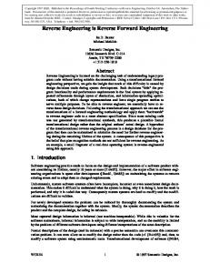
The transformation for one PIM to several PSMs is at the core of MDA. A model-driven forward engineering process is carried out as a sequence of model transformations that includes, at least, the following steps: construct a CIM; transform the CIM into a PIM that provides a computing architecture independent of specific platforms; transform the PIM into one or more PSMs, and derive code directly from the PSMs. We can distinguish three types of transformations to support model evolution in forward and reverse engineering processes: refinements, code-to-models and refactorings. A refinement is the process of building a more detailed specification that conforms to another that is more abstract. On the other hand, a code-to-model transformation is the process of extracting from a more detailed specification (or code) another one, more abstract, that is conformed by the more detailed specification. Refactoring means changing a model leaving its behavior unchanged, but enhancing some non-functional quality factors such as simplicity, flexibility, understandability and performance. Metamodel transformations are contracts between a source metamodel and a target metamodel and describe families of transformations. Figure 1 partially depicts the different kind of transformations and the relationships between models and metamodels. The MOF 2.0 Query, View, Transformation (QVT) specification is the OMG standard for model transformations (QVT, 2008). The acronym QVT refers to:
Query: ad-hoc “query” for selecting and filtering of model elements. In general, a query selects elements of the source model of the transformation. View: “views” of MOF metamodels (that are involved in the transformation). Transformation: a relation between a source metamodel S and a target metamodel T that is used to generate a target model (that conforms to T) from a source model (that conforms to S).
QVT defines a standard for transforming a source model into a target model. One of the underlying ideas in QVT is that the source and target model must conform to arbitrary MOF metamodels. Another concept is that the transformation is considered itself as a model that conforms to a MOF metamodel. The QVT specification has a hybrid declarative/imperative nature. The declarative part of this specification is structured in two layers:
A user-friendly Relations metamodel and language which supports the creation of object template, complex object pattern matching and the creation of traces between model elements involved in a transformation. A Core metamodel and language defined using minimal extensions to EMOF and OCL. All trace classes are explicitly defined as MOF models, and trace instance creation and deletion is in the same way as the creation and deletion of any other object. This specification describes three related transformational languages: Relations, Core and Operational Matching.
62
Reverse Engineering – Recent Advances and Applications
Fig. 1. Model, metamodels and transformations 2.2 MDA case tools The success of MDA depends on the existence of CASE tools that make a significant impact on software processes such as forward engineering and reverse engineering processes, however all of the MDA tools are partially compliant to MDA features. The main limitations of MDA tools are related to the incipient evolution of metamodeling standards such as QVT or KDM and to the lack of specification (in terms of MDA standards) of various platforms. The article (Stevens, 2008) argues that a considerable amount of basic research is needed before suitable tools will be fully realizable. The major developments taking place in the framework of the Eclipse project (Eclipse, 2011). For instance, the Eclipse Modeling Framework (EMF) was created for facilitating system modeling and the automatic generation of Java code. EMF started as an implementation of MOF resulting Ecore, the EMF metamodel comparable to EMOF. EMF has evolved starting from the experience of the Eclipse community to implement a variety of tools and to date is highly related to Model Driven Engineering (MDE). For instance, ATL (Atlas Transformation Language) is a model transformation language in the field of MDE that is developed on top of the Eclipse platform (ATL, 2011). Commercial tools such as IBM Rational Software Architect, Spark System Enterprise Architect or Together are integrated with Eclipse-EMF (CASE MDA, 2011). Few MDA-based CASE tools support QVT or at least, any of the QVT languages. As an example, IBM Rational Software Architect and Spark System Enterprise Architect do not
MDA-Based Reverse Engineering
63
implement QVT. Other tools partially support QVT, for instance Together allows defining and modifying transformations model-to-model (M2M) and model-to-text (M2T) that are QVT-Operational compliant. Medini QVT partially implements QVT (Medini, 2011). It is integrated with Eclipse and allows the execution of transformations expressed in the QVTRelation language. Eclipse M2M, the official tool compatible with of Eclipse 3.5 and EMF 2.5.0, is still under development and implements the specification of QVT-Operational. Blu Age and Modisco are ADM compliant Case tools and built on Eclipse that allow reverse engineering (Modisco, 2011) (CASE MDA, 2011). Modisco is considered by ADM as the reference provider for real implementations of several of its standards such as KDM and Abstract Syntax Tree Metamodel (ASTM), in particular. MoDisco provides an extensible framework to develop model-driven tools to support use-cases of existing software modernization. It uses EMF to describe and manipulate models, M2M to implement transformation of models into other models, Eclipse M2T to implement generation of text and Eclipse Java Development Tools (JDT). At the moment, Modisco supports reverse engineering of class diagrams. Some interesting challenges are still open in it, for instance, reverse engineering of different UML diagrams and scalability. Another limitation of the MDA tools has to do with model validation. Reasoning about models of systems is well supported by automated theorem provers and model checkers, however these tools are not integrated into CASE tools environments. Only research tools provide support for formal specification and deductive verification. As an example, we can mention USE 3.0 that is a system for specification of information systems in OCL. USE allows snapshots of running systems can be created and manipulated during an animation, checking OCL constraints to validate the specification against non-formal requirements (Use, 2011) (OCL USE, 2011).
3. Metamodel formalization The essence of MDA is metamodeling, MOF in particular. OCL is widely used by MOFbased metamodels to constrain and perform evaluations on them. OCL contains many inconsistencies and evolves with MDA standards (Willink, 2011). OCL has a denotational semantics that has been implemented in tools that allow dynamic validation of snapshots. However, it cannot be considered strictly a formal specification language due to a formal language must at least provide syntax, some semantics and an inference system. The syntax defines the structure of the text of a formal specification including properties that are expressed as axioms (formulas of some logic). The semantics describes the models linked to a given specification; in the formal specification context, a model is a mathematical object that defines behavior of the realizations of the specifications. The inference system allows defining deductions that can be made from a formal specification. These deductions allow new formulas to be derived and checked. So, the inference system can help to automate testing, prototyping or verification. A combination of MOF metamodeling and formal specification can help us to address MDA-based processes such as forward engineering and reverse engineering. In light of this we define a special-purpose language, called NEREUS, to provide extra support for metamodeling. NEREUS takes advantage of existing theoretical background on formal methods, for instance, the notions of refinement, implementation correctness, observable equivalences and behavioral equivalences that play an essential role in model-to-model
64
Reverse Engineering – Recent Advances and Applications
transformations. Most of the MOF metamodel concepts can be mapped directly to NEREUS. The type system of NEREUS was defined rigorously in the algebraic framework. The semantics of MOF metamodels (that is specified in OCL) can be enriched and refined by integrating it with NEREUS. This integration facilitates proofs and tests of models and model transformations via the formal specification of metamodels. Some properties can be deduced from the formal specification and could be re-injected into the MOF specification without wasting the advantages of semi-formal languages of being more intuitive and pragmatic for most implementers and practitioners. Our approach has two main advantages linked to automation and interoperability. On the one hand, we show how to generate automatically formal specifications from MOF metamodels. Due to scalability problems, this is an essential prerequisite. We define a system of transformation rules for translating MOF metamodels specified in OCL into algebraic languages. On the other hand, our approach focuses on interoperability of formal languages. Languages that are defined in terms of NEREUS metamodels can be related to each other because they are defined in the same way through a textual syntax. Any number of source languages such as different DSLs and target languages (different formal language) could be connected without having to define explicit metamodel transformations for each language pair. Such as MOF is a DSL to define semi-formal metamodels, NEREUS can be viewed as a DSL for defining formal metamodels. In addition to define strictly the type system, NEREUS, like algebraic languages, allows finding instance models that satisfy metamodel specification. Semiformal metamodels such as MOF do not find instance models and only detect constraint violations. Another advantage of our approach is linked to pragmatic aspects. NEREUS is a formal notation closed to MOF metamodels that allows meta-designers who must manipulate metamodels to understand their formal specification. NEREUS allows specifying metamodels such as the Ecore metamodel, the specific metamodel for defining models in EMF (Eclipse Modeling Framework) (Eclipse, 2010). Today, we are integrating NEREUS in EMF. 3.1 NEREUS language specification NEREUS consists of several constructs to express classes, associations and packages and a repertoire of mechanisms for structuring them. Next, we show the syntax of a class in NEREUS: CLASS className [] IMPORTS IS-SUBTYPE-OF INHERITS GENERATED-BY DEFERRED TYPES
OPERATIONS EFFECTIVE TYPES OPERATIONS AXIOMS END-CLASS
NEREUS distinguishes variable parts in a specification by means of explicit parameterization. The IMPORTS clause expresses client relations. The specification of the new class is based on the imported specifications declared in and their public operations may be used in the new specification. NEREUS distinguishes inheritance from
MDA-Based Reverse Engineering
65
subtyping. Subtyping is like inheritance of behavior, while inheritance relies on the module viewpoint of classes. Inheritance is expressed in the INHERITS clause, the specification of the class is built from the union of the specifications of the classes appearing in the . Subtypings are declared in the IS-SUBTYPE-OF clause. A notion closely related with subtyping is polymorphism, which satisfies the property that each object of a subclass is at the same time an object of its superclasses. NEREUS allows us to define local instances of a class in the IMPORTS and INHERITS clauses. NEREUS distinguishes deferred and effective parts. The DEFERRED clause declares new types or operations that are incompletely defined. The EFFECTIVE clause either declares new sorts or operations that are completely defined, or completes the definition of some inherited sort or operation. Attributes and operations are declared in ATTRIBUTES and OPERATIONS clauses. NEREUS supports higher-order operations (a function f is higherorder if functional sorts appear in a parameter sort or the result sort of f). In the context of OCL Collection formalization, second-order operations are required. In NEREUS it is possible to specify any of the three levels of visibility for operations: public, protected and private. NEREUS provides the construction LET… IN.. to limit the scope of the declarations of auxiliary symbols by using local definitions. NEREUS provides a taxonomy of type constructors that classifies associations according to kind (aggregation, composition, association, association class, qualified association), degree (unary, binary), navigability (unidirectional, bidirectional) and connectivity (one-to one, one-to-many, many-to-many). New associations can be defined by the ASSOCIATION construction. The IS clause expresses the instantiation of with classes, roles, visibility, and multiplicity. The CONSTRAINED-BY clause allows the specification of static constraints in first order logic. Next, we show the association syntax: ASSOCIATION IS […:class1;…:class2;…:role1;…:role2;…:mult1;…:mult2;…:visibility1;…:visibility2] CONSTRAINED-BY END Associations are defined in a class by means of the ASSOCIATES clause: CLASS className… ASSOCIATES … END-CLASS The PACKAGE construct groups classes and associations and controls its visibility. lists the imported packages; lists the inherited packages and are classes, associations and packages. Next, we show the package syntax: PACKAGE packageName IMPORTING GENERALIZATION NESTING CLUSTERING END-PACKAGE
66
Reverse Engineering – Recent Advances and Applications
NEREUS is an intermediate notation open to many other formal languages such as algebraic, logic or functional. We define its semantics by giving a precise formal meaning to each of the constructs of the NEREUS language in terms of the CASL language (Bidoit & Mosses, 2004). 3.2 Transforming metamodels into NEREUS We define a bridge between EMOF- and Ecore- metamodels and NEREUS. The NEREUS specification is completed gradually. First, the signature and some axioms of classes are obtained by instantiating reusable schemes. Associations are transformed by using a reusable component ASSOCIATION. Next, OCL specifications are transformed using a set of transformation rules and a specification that reflects all the information of MOF metamodels is constructed. The OCL basic types are associated with NEREUS basic types with the same name. NEREUS provides classes for collection type hierarchies. The types Set, Ordered Set, Bag and Sequence are subtypes of Collection. The transformation process of OCL specifications to NEREUS is supported by a system of transformation rules. By analyzing OCL specifications we can derive axioms that will be included in the NEREUS specifications. Preconditions written in OCL are used to generate preconditions in NEREUS. Postconditions and invariants allow us to generate axioms in NEREUS. We define a system of transformation rules that only considers expressions based on Essential OCL (OCL, 2010). The following metaclasses defined in complete OCL are not part of the EssentialOCL: MessageType, StateExp, ElementType, AssociationClassCallExp, MessageExp, and UnspecifiedValueExp. Any well-formed rules defined for these classes are consequently not part of the definition of the transformation rule system. The system includes a small set with around fifty rules. It was built by means of an iterative approach through successive refinements. The set of rules was validated by analyzing the different OCL expression attached to the UML metamodels, MOF and QVT. As an example we show a few rules of the system. A detailed description of the system may be found at (Favre, 2010). In each rule the shaded text denotes an OCL expression that can be translated by the non-shaded text in NEREUS: Rule
OCL NEREUS
R1
v. operation(parameters) operation(TranslateNEREUS(v),TranslateNEREUS (parameters))
R2
v->operation (parameters) operation(TranslateNEREUS(v),TranslateNEREUS (parameters))
R3
v.attribute attribute (v)
R4
context Assoc object.rolename Let a:Assoc get_rolename (a, object)
MDA-Based Reverse Engineering
R5
e.op e: expression op(TranslateNEREUS(e))
R6
exp1 infix-op exp2 TranslateNEREUS(exp1)TranslateNEREUS(infix-op) TranslateNEREUS(exp2) TranslateNEREUS(infix-oper) (TranslateNEREUS(exp1),TranslateNEREUS(exp2))
R7
T-> operationName (v :Type | bool-expr-with-v) OperationName ::= forAll│exists│select│reject T ::= Collection|Set|OrderedSet|Bag operationName (v) (TranslateNEREUS (T), [TranslateNEREUS (bool-expr-with-v)])
67
As an example, we show the formalization in NEREUS of a simplified QVT Core metamodel (Figure 2). The Core language is as powerful as the Relation language and may be used as a reference for the semantics of relations, which are mapped to Core. The complete diagram may be found at (QVT, 2008, pp.15). Figure 2 shows a simplified metamodel including transformation and rules classes.
Fig. 2. A simplified metamodel A transformation defines how one set of models can be transformed into another. It is composed by a set of rules that specify its execution behavior. The following constraints (extendingRule and transitiveRule) may be attached to Figure 2 specifying that the rules of the extended transformation are included in the extending transformation and the extension is transitive: extendingRule = Transformation.allInstances -> forAll (t |t.extends.size = 1 implies t.extends.rule -> include (t.rule)) transitiveRule = Transformation.allInstances -> forAll (t1, t2, t3 | t1.extends.size = 1 and t2.extends.size = 1 and t3.extends.size = 1 and (t1.extends.rule -> includes (t2.rule) and t2.extends.rule -> includes (t3.rules)) implies t1.extends.rule -> includes (t3.rule) The OCL specification, extendingRule and transformationRule can be translated into the shaded axioms of the following specification: PACKAGE QVTBase CLASS Transformation IMPORTS EMOF::Tag INHERITS EMOF::MetaClass, EMOF::Package
68
Reverse Engineering – Recent Advances and Applications
ASSOCIATES AXIOMS ass1: ; ass2: ; t: Transformation ;… size (get_extends (ass1, t)) = 1 implies includes (get_rule (ass2, get_extends (ass1, t)), get_rule (ass1, t)) END-CLASS CLASS TypedModel IMPORTS EMOF::Package IS-SUBTYPE-OF EMOF::NamedElement ASSOCIATES END-CLASS CLASS Domain IS-SUBTYPE-OF EMOF::NamedElement ASSOCIATES DEFERRED ATTRIBUTES isCheckable: Domain -> Boolean isEnforceable: Domain -> Boolean END-CLASS CLASS Rule IS-SUBTYPE-OF EMOF::NamedElement ASSOCIATES END-CLASS ASSOCIATION Transformation-Transformation IS Unidirectional-2 [Transformation: class1; Transformation: class2; extendedBy: role1; extends: role2; *: mult1; 0..1: mult2; +: visibility1; + : visibility2] END-ASSOCIATION ASSOCIATION Transformation-Rule IS Composition-2 [Transformation: class1; Rule: class2; transformation: role1; rule: role2; 1: mult1; *: mult2; +: visibility1; +: visibility2] END-ASSOCIATION... END-PACKAGE NEREUS can be integrated with object-oriented languages such as Eiffel. The article (Favre, 2005) describes a forward engineering process from UML static models to object-oriented code. More information related to the NEREUS approach may be found at (Favre, 2010) and (Favre, 2009). However, we would like remark that here NEREUS is used as an intermediate formal notation to communicate the essential of an MDA reverse engineering approach.
4. Reverse engineering of object-oriented code In this section we analyze traditional reverse engineering techniques based on static and dynamic analysis. We show how to reverse engineering object-oriented code to models, in
MDA-Based Reverse Engineering
69
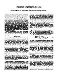
particular. Static analysis extracts static information that describes the structure of the software reflected in the software documentation (e.g., the text of the source code) while dynamic analysis information describes the structure of the run-behavior. Static information can be extracted by using techniques and tools based on compiler techniques such as parsing and data flow algorithms. On the other hand, dynamic information can be extracted by using debuggers, event recorders and general tracer tools. Figure 3 shows the different phases. The source code is parsed to obtain an abstract syntax tree (AST) associated with the source programming language grammar. Next, a metamodel extractor extracts a simplified, abstract version of the language that ignores all instructions that do not affect the data flows, for instance all control flows such as conditional and loops. The information represented according to this metamodel allows building the OFG for a given source code, as well as conducting all other analysis that do not depend on the graph. The idea is to derive statically information by performing a propagation of data. Different kinds of analysis propagate different kinds of information in the data-flow graph, extracting the different kinds of diagrams that are included in a model. The static analysis is based on classical compiler techniques (Aho, Sethi & Ullman, 1985) and abstract interpretation (Jones & Nielson, 1995). The generic flow propagation algorithms are specializations of classical flow analysis techniques. Because there are many possible executions, it is usually not reasonable to consider all states of the program. Thus, static analysis is based on abstract models of the program state that are easier to manipulate, although lose some information. Abstract interpretation of program state allows obtaining automatically as much information as possible about program executions without having to run the program on all input data and then ensuring computability or tractability. The static analysis builds a partial model (PIM or PSM) that must be refined by dynamic analysis. Dynamic analysis is based on testing and profiling. Execution tracer tools generate execution model snapshots that allow us to deduce complementary information. Execution models, programs and UML models coexist in this process. An object-oriented execution model has the following components: a set of objects, a set of attributes for each object, a location for each object, each object refers to a value of an object type and, a set of messages that include a name selector and may include one or more arguments. Additionally, types are available for describing types of attributes and parameters of methods or constructors. On the other hand, an object-oriented program model has a set of classes, a set of attributes for each class, a set of operations for each class, and a generalization hierarchy over classes. The combination of static and dynamic analysis can enrich the reverse engineering process. There are different ways of combination, for instance performing first static analysis and then dynamic analysis or perhaps iterating static and dynamic analysis. 4.1 Static analysis The concepts and algorithms of data flow analysis described in (Aho, Sethi & Ullman, 1985) are adapted for reverse engineering object-oriented code. Data flow analysis infers information about the behavior of a program by only analyzing the text of the source code. The basic representation of this static analysis is the Object Flow Graph (OFG) that allows tracing information of object interactions from the object creation, through object assignment
70
Reverse Engineering – Recent Advances and Applications
to variables, attributes or their use in messages (method invocations). OFG is defined as an oriented graph that represents all data flows linking objects. The static analysis is data flow sensitive, but control flow insensitive. This means that programs with different control flows and the same data flows are associated with the same analysis results. The choice of this program representation is motivated by the computational complexity of the involved algorithms. On the one hand, control flow sensitive analysis is computationally intractable and on the other hand, data flow sensitive analysis is aligned to the “nature” of the object-oriented programs whose execution models impose more constraints on the data flows than on the control flows. For example, the sequence of method invocations may change when moving from an application which uses a class to another one, while the possible ways to copy and propagate object references remains more stable. A consequence of the control flow insensitivity is that the construction of the OFG can be described with reference to a simplified, abstract version of the object-oriented languages in which instructions related to flow control are ignored. A generic algorithm of flow propagation working on the OFG processes object information. In the following, we describe the three essential components of the common analysis framework: the simplified abstract object-oriented language, the data flow graph and the flow propagation algorithm.
Fig. 3. Static and dynamic analysis
71
MDA-Based Reverse Engineering
All instructions that refer to data flows are represented in the abstract language, while all control flow instructions such as conditional and different iteration constructs are ignored. To avoid name conflicts all identifiers are given fully scoped names including a list of enclosing packages, classes and methods. The abstract syntax of a simplified language (Tonella & Potrich, 2005) is as follows: (1)
P
::=
D*S*
(2)
D
::=
a
(3)
m (p1,p2,…,pj)
(4)
cons (p1,p2,…,pj)
::=
x = new c (a1,a2,…aj)
(6)
x=y
(7)
[x = ] y.m (a1,a2,…,aj)
(5)
S
Some notational conventions are considered: non-terminals are denoted by upper case letters; a is class attribute name; m is method name; p1, p2,…pj are formal parameters; a1,a2,…aj are actual parameters and cons is class constructor and c is class name. x and y are program locations that are globally data objects, i.e. object with an address into memory such as variables, class attributes and method parameters A program P consists of zero or more declarations (D*) concatenated with zero or more statements (S*). The order of declarations and statements is irrelevant. The nesting structure of packages, classes and statements is flattened, i.e. statements belonging to different methods are identified by using their fully scope names for their identifiers. There are three types of declarations: attribute declarations (2), method declarations (3) and constructor declaration (4). An attribute declaration is defined by the scope determined by the list of packages, classes, followed by the attribute identifier. A method declaration consists in its name followed by a list of formal parameter (p1,p2,…pj). Constructors have a similar declaration. There are three types of statement declarations: allocation statements (5), assignments (6) and method invocation (7). The left hand side and the right hand side of all statements is a program location. The target of a method invocation is also a program location. The process of transformation of an object-oriented program into a simplified language can be easily automated. The Object Flow Graph (OFG) is a pair (N, E) where N is a set of nodes and E is a set of edges. A node is added for each program location (i.e. formal parameter or attribute). Edges represent the data flows appearing in the program. They are added to the OFG according to the rules specified in (Tonella & Potrich, 2005, pp. 26). Next, we describe the rules for constructing OFG from Java statements:
72 (1) (2) (3) (4) (5) (6) (7)
Reverse Engineering – Recent Advances and Applications
P D
S
::= ::= ::=
D*S* a m (p1,p2,…,pj) cons (p1,p2,…,pj) x = new c (a1,a2,…aj) x=y [x = ] y.m (a1,a2,…,aj)
{} {} {} {} {(a1,p1) E,..(aj,pj) E, (cons.this,x) E} {(y,x) E} {(y, m.this) E, (a1,p1) E,..(aj,pj)E, (m.return,x) E}
When a constructor or method is invoked, edges are built which connect each actual parameter ai to the respective formal parameter pi. In case of constructor invocation, the newly created object, referenced by cons.this is paired with the left hand side x of the related assignment. In case of method invocation, the target object y becomes m.this inside the called method, generating the edge (y, m.this), and the value returned by method m (if any) flows to the left hand side x (pair (m.return, x)). Some edges in the OFG may be related to object flows that are external to the analyzed code. Examples of external flows are related with the usage of class libraries, dynamic loading (through reflection) or the access to modules written in other programming language. Due to these external flows can be treated in a similar way next, we show how to affect the OFG the usage of class libraries. Each time a library class introduces a data flow from a variable x to a variable y an edge (x,y) must be included in the OFG. Containers are an example of library classes that introduce external data flows, for instance, any Java class implementing the interface Collection or the interface Map. Object containers provide two basic operations affecting the OFG: insert and extract for adding an object to a container and accessing an object in a container respectively. In the abstract program representation, insertion and extraction methods are associated with container objects. Next, we show a pseudo-code of a generic forward propagation algorithm that is a specific instance of the algorithms applied to control flow graph described in (Aho, Sethi & Ullman, 1985): for each node n N in[n] = {}; out[n]= gen[n] U (in[n] - kill[n]) endfor while any in[n] or out[n] changes for each node n N in[n] = Uppred(n) out[p]; out[n] = gen[n] U(in[n] - kill[n]) endfor endwhile Let gen[n] and kill[n] be two sets of each basic node n N. gen[n] is the set of flow information entities generated by n. kill[n] is the set of definition outside of n that define entities that also have definitions within n. There are two sets of equations, called data-flow equations that relate incoming and outgoing flow information inside the sets:
MDA-Based Reverse Engineering
73
in[n] = Uppred(n) out[p] out[n] = gen[n] U (in[n] - kill[n]) Each node n stores the incoming and outgoing flow information inside the sets in[n] and out[n], which are initially empty. Each node n generates the set of flow information entities included in gen[s] set, and prevents the elements of kill[n] set from being further propagated after node n. In forward propagation in[n] is obtained from the predecessors of node n as the union of the respective out sets. The OFG based on the previous rules is “object insensitive”; this means that it is not possible to distinguish two locations (e.g. two class attributes) when they belongs to different class instances. An object sensitive OFG might improve the analysis results. It can be built by giving all non-static program locations an object scope instead of a class scope and objects can be identified statically by their allocation points. Thus, in an object sensitive OFG, nonstatic class attributes and methods with their parameters and local variables, are replicated for every statically identified object. 4.2 Dynamic analysis Dynamic analysis operates by generating execution snapshots to collect life cycle traces of object instances and observing the executions to extract information. Ernst (2003) argues that whereas the chief challenge of static analysis is choosing a good abstract interpretation, the chief challenge of performing good dynamic analysis is selecting a representative set of test cases. A test case can help to detect properties of the program, but it can be difficult to detect whether results of a test are true program properties or properties of a particular execution context. The main limitation of dynamic analysis is related to the quality of the test cases used to produce diagrams. Integrating dynamic and static analysis seems to be beneficial. The static and dynamic information could be shown as separated views or merged in a single view. In general, the outcome of the dynamic analysis could be visualized as a set of diagrams, each one associated with one execution trace of a test case. Although, the construction of these diagrams can be automated, their analysis requires human intervention in most cases. Dynamic analysis depends on the quality of the test cases. Maoz and Harel (2010) present a powerful technique for the visualization and exploration of execution traces of models that is different from previous approaches that consider execution traces at the code level. This technique belongs to the domain of model-based dynamic analysis adapting classical visualization paradigms and techniques to specific needs of dynamic analysis. It allows relating the system execution traces and its models in different tasks such as testing whether a system run satisfies model properties. We consider that these results allow us to address reverse engineering challenges in the context of modeldriven development. 4.3 An example: Recovering class diagram In this section we describe how to extract class diagrams from Java code. A class diagram is a representation of the static view that shows a collection of static model elements, such as
74
Reverse Engineering – Recent Advances and Applications
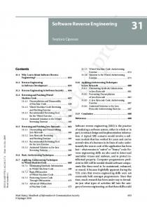
classes, interfaces, methods, attributes, types as well as their properties (e.g., type and visibility). Besides, the class diagram shows the interrelationships holding among the classes (UML, 2010a; UML, 2010b). Some relevant work for automatic extraction of UML class diagram is present in the literature (Telea et al, 2009) (Milanova, 2007). Reverse engineering of UML class diagram annotated in OCL from code is difficult task that cannot be fully automated. Certain elements in the class diagram carry behavioral information that cannot be inferred just from the analysis of the code. A basic algorithm to extract class diagrams can be based on a purely syntactic analysis of the source code. Figure 4 shows relationships that can be detected in this way between a Java program and a UML class diagram. By analyzing the syntax of the source code, internal class features such as attributes and methods and their properties (e.g. the parameters of the methods and visibility) can be recovered. From the source code, associations, generalization, realizations and dependencies may be inferred too.
Fig. 4. ISM Java constructs versus PSM Java constructs The main problems of the basic syntactic analysis are linked to the fact that declared types are an approximation of the classes instantiated due to inheritance and interfaces or, the
MDA-Based Reverse Engineering
75
usage of weakly typed container. Then, associations determined from the types of container declarations in the text do not specify the type of the contained object. A specialization of the generic forward propagation algorithm shown in 4.1 can be defined to solve this problem. Another problem is how to distinguish between aggregation or composition. For instance, the association between A and B (Figure 4) could be an aggregation or a composition. An aggregation models the situation where an object is made up of several parts. Other properties that characterize the aggregation are the following:
type-anti-symmetry: the aggregation from a type A (as whole) to a type B (as part), prevents the existence of another aggregation from B ( as a whole) to A ( as part) instance-reflexivity instance anti-symmetry
Milanova (2007) proposes an implementation-level ownership and composition model and a static analysis for identifying composition relationships in accordance with the model. In addition, they present an evaluation which shows that the analysis achieves “almost perfect precision, that is, it almost never misses composition relationships”. Another problem is how to infer OCL specifications (e.g. preconditions and postconditions of operations, invariants and association constraints) from code. In these cases, we need to capture system states through dynamic analysis. Dynamic analysis allows generating execution snapshot to collect life cycle traces of object instances and reason from tests and proofs. Execution tracer tools generate execution model snapshots that allow us to deduce complementary information. The execution traces of different instances of the same class or method, could guide the construction of invariants or pre- and post-conditions respectively. Dynamic analysis could also help to detect lifetime dependencies in associations scanning dependency configurations between the birth and death of a part object according to those of the whole.
5. Specifying metamodel-based transformations We specify reverse engineering processes as MOF-based transformations. Metamodel transformations impose relations between a source metamodel and a target metamodel, both represented as MOF-metamodels. The transformations between models are described starting from the metaclass of the elements of the source model and the metaclass of the elements of the target model. The models to be transformed and the target models will be instances of the corresponding metamodel. Transformation semantics is aligned with QVT, in particular with the QVT Core. QVT depends on EssentialOCL (OCL, 2010) and EMOF (MOF, 2006). EMOF is a subset of MOF that allows simple metamodels to be defined using simple concepts. Essential OCL is a package exposing the minimal OCL required to work with EMOF. A code-to-model transformation is the process of extracting from a more detailed specification (or code) another one, more abstract, that is conformed to the more detailed
76
Reverse Engineering – Recent Advances and Applications
specification. Next, we describe how to specify code-to-model transformations within the proposed framework. Figure 5.b shows partially an ISM-Java metamodel that includes constructs for representing classes, fields and operations. It also shows different kind of relationships such as composition and generalization. For example, an instance of JavaClass could be related to another instance of JavaClass that takes the role of superclass or, it could be composed by other instances of JavaClass that take the role of nestedClass. Figure 5.b shows the metamodel for operations. An operation is a subtype of the metaclass Operation of the UML kernel. There is a generalization between operation, constructor and method and so on. Figure 5.a shows partially a PSM-Java metamodel that includes constructs for representing classes, fields, operations and association-ends. It also shows different kind of relationships such as composition and generalization. For example, an instance of JavaClass could be related to another instance of JavaClass that takes the role of superclass or, it could be composed by other instances of JavaClass that takes the role of nestedClass. The main difference between a Java-ISM and a Java-PSM is that the latter includes constructs for associations. The transformation specification is an OCL contract that consists of a name, a set of parameters, a precondition and postconditions. The precondition states relations between the metaclasses of the source metamodel. The postconditions deal with the state of the models after the transformation. Next, a model-to-code transformation between an ISM-Java and a PSM-Java is partially specified. Transformation ISM-Java to PSM-Java parameters source: ISM-JavaMetamodel::JavaPackage target: PSM-JavaMetamodel ::Java Package postconditions let SetClassSource: Set[ISM-JavaMetamodel::JavaPackage::JavaClass] = source.ownedMember -> select (oclIsKindOf (JavaPackage).javaClasses in /*for each Java class in the ISM exists a PSM class with the same name*/ SetClassSource -> forAll (sClass| target.ownedMember ->select (oclIsKindOf (JavaClass))-> exists (tClass|sClass.name = tClass.name) and /*for each associationEnd of a class in the PSM exists a private attribute of the same name in the ISM*/ sClass.fields->forAll (sField| SetClassSource-> exists (tc1| tc1.type = sField.type implies tc1.associationEnd -> includes (sField.type) and /*for each extends relation in Java exists a generalization in the PSM*/
MDA-Based Reverse Engineering
77
(source.ownedMember -> select(oclIsKindOf (JavaClass).extendingClass -> includes(sClass)) implies SetClassSource -> exists (t1 | t1.superclass.name = sClass.name)…
Fig. 5. PSM and ISM Java Metamodels
78
Reverse Engineering – Recent Advances and Applications
6. Summing up the parts: A framework for reverse engineering In this section we propose an integration of traditional compiler techniques, metamodeling and formal specification. Figure 6 shows a framework for reverse engineering that distinguishes three different abstraction levels linked to models, metamodels and formal specifications.
Fig. 6. An MDA-based Reverse Engineering Framework The model level includes code, PIMs and PSMs. A PIM is a model with a high-level of abstraction that is independent of an implementation technology. A PSM is a tailored model to specify a system in terms of specific platform such J2EE or .NET. PIMs and PSMs are expressed in UML and OCL (UML, 2010a) (UML, 2010b) (OCL, 2010). The subset of UML diagrams that are useful for PSMs includes class diagram, object diagram, state diagram, interaction diagram and package diagram. On the other hand, a PIM can be expressed by means of use case diagrams, activity diagrams, interactions diagrams to model system processes and state diagrams to model lifecycle of the system entities. An ISM is a specification of the system in source code. At model level, transformations are based on static and dynamic analysis. The metamodel level includes MOF metamodels that describe the transformations at model level. Metamodel transformations are specified as OCL contracts between a source metamodel and a target metamodel. MOF metamodels “control” the consistency of these transformations.
MDA-Based Reverse Engineering
79
The level of formal specification includes specifications of MOF metamodels and metamodel transformations in the metamodeling language NEREUS that can be used to connect them with different formal and programming languages. Our framework could be considered as an MDA-based formalization of the process described by Tonella and Potrich (2005). In this chapter we exemplify the bases of our approach with Class Diagram reverse engineering. However, our results include algorithms for extracting different UML diagrams such as interaction diagram, state diagram, use case diagram and activity diagram (Favre, 2010) (Favre, Martinez & Pereira, 2009) (Pereira, Martinez & Favre, 2011) (Martinez, Pereira, & Favre, 2011).
7. Challenges and strategic directions Nowadays, software and system engineering industry evolves to manage new platform technologies, design techniques and processes. Architectural frameworks for information integration and tool interoperation, such as MDA, had created the need to develop new analysis tools and specific techniques. A challenge on reverse engineering is the necessity to achieve co-evolution between different types of software artifacts or different representations of them. MDA allows us to develop and relate all different artifacts in a way that ensures their inter-consistency. MDA raises the level of reasoning to a more abstract level and therefore even more appropriate placing change and evolution in the center of software development process. The integration of business models with PIM, PSMs and code is a crucial challenge in MDA. Existing formal methods provide a poor support for evolving specifications and incremental verification approaches. In particular, with the existing verification tools, simple changes in a system require to verify its complete specification again making the cost of the verification proportional to its size. To use formal methods that place change and evolution in the center of the software development process is another challenge. The progress in the last decade in scalability and incremental verification of formal methods could impact in MDA reverse engineering processes. OMG is involved in the definition of standards to successfully modernize existing information systems. Concerning ADM, current work involves building standards to facilitate the exchange of existing systems meta-data for various modernization tools. The main limitations of MDA tools are related to the incipient evolution of MDA standards such as QVT or KDM and to the lack of specification in terms of these standards of various platforms and bridges between platforms. In summary, a lot remains to be done to provide support for MDA-based software evolution: research on formalisms and theories to increase understanding of software evolution processes; development of methods, techniques and heuristics to provide support for software changes; new verification tools that embrace change and evolution as central in software development processes; development of new sophisticated tools to develop industrial size software systems and definition of standards to evaluate the quality of evolved artifacts/systems.
80
Reverse Engineering – Recent Advances and Applications
Perhaps, another impediment is the culture change that accompanies this approach. The adoption of reverse engineering techniques in general, should be favored by educating future generations of software engineers, i.e., integrating background on these topics into the computer science curriculum.
8. References ADM (2010). Standards Roadmap. ADM Task Force. Retrieved October 2011 from adm.omg.org Aho, A., Sethi, R., & Ullman, J. (1985). Compilers: Principles, Techniques, and Tools (2nd ed.). Reading: Addison-Wesley. ANSI-IEEE. (1984). ANSI/IEEE Software Engineering Standards: Std 729-1983, Std 730-1884, Std 828-1983, 829-1984, 830-1984. Los Alamitos: IEEE/Wiley. ATL (2011). ATL Documentation. Retrieved October 2011 from www.eclipse.org/m2m/atl/documentation Bidoit, M., & Mosses, P. (2004). CASL User Manual- Introduction to Using the Common Algebraic Specification Language (LNCS 2900). Heidelberg: Springer-Verlag. Canfora, G., & Di Penta, M. (2007). New Frontiers of Reverse Engineering. Future of Software engineering. In Proceedings of Future of Software Engineering (FOSE 2007) (pp. 326-341). Los Alamitos:IEEE Press. CASE MDA (2011). Retrieved October 2011 from www.case-tools.org Chikofsky, E., & Cross, J. (1990). Reverse engineering and design recovery: A taxonomy. IEEE Software, 7(1), 13–17. doi:10.1109/52.43044 Eclipse (2011). The eclipse modeling framework. Retrieved October 2011 from http://www.eclipse.org/emf/ Ernst, M. (2003). Static and Dynamic Analysis: Synergy and duality. In Proceedings of ICSE Workshop on Dynamic Analysis (WODA 2003) (pp. 24-27). Fanta, R., & Rajlich, V. (1998). Reengineering object-oriented code. In Proceedings of International Conference on Software Maintenance (pp. 238-246). Los Alamitos: IEEE Computer Society. Favre, L. (2005) Foundations for MDA-based Forward Engineering. Journal of Object Technology (JOT), Vol 4, N° 1, Jan/Feb, 129-153. Favre, L. (2009). A Formal Foundation for Metamodeling. ADA Europe 2009. Lecture Notes in Computer Science (Vol. 5570, pp. 177-191). Heidelberg: Springer-Verlag. Favre, L., Martinez, L., & Pereira, C. (2009). MDA-based Reverse Engineering of Objectoriented Code. Lecture Notes in Business Information Processing (Vol 29, pp. 251-263). Heidelberg: Springer-Verlag. Favre, L. (2010). Model Driven Architecture for Reverse Engineering Technologies: Strategic Directions and System Evolution. Engineering Science Reference, IGI Global, USA. Jones, N., & Nielson, F. (1995). Abstract interpretation: A semantic based tool for program analysis. In D. Gabbay, S. Abramsky, & T. Maibaum (Eds), Handbook of Logic in Computer Science (Vol. 4, pp. 527-636). Oxford: Clarendon Press. KDM (2011). Knowledge Discovery Meta-Model, Version 1.3-beta 2, March 2011. OMG specification formal 2010-12-12. Retrieved October 2011 from http://www.omg.org/spec/kdm/1.3/beta2/pdf
MDA-Based Reverse Engineering
81
Maoz, S., & Harel, D. (2010) On Tracing Reactive Systems. Software & System Modeling. DOI 10.1007/510270-010-0151-2, Springer-Verlag. MDA (2005). The Model Driven Architecture. Retrieved October 2011 from www.omg.org/mda. Martinez, L., Pereira, C., & Favre, L. (2011) Recovering Activity Diagrams from ObjectOriented Code: an MDA-based Approach. In Proceedings 2011 International Conference on Software Engineering Research and Practice (SERP 2011)(Vol. I, pp. 5864), CSREA Press. Medini (2011). Medini QVT. Retrieved October 2011 from http://projects.ikv.de/qvt Milanova, A. (2007). Composition Inference for UML Class Diagrams. Journal Automated Software Engineering. Vol 14 Issue 2, June. Modisco (2011). Retrieved October 2011 from http://www.eclipse.org/Modisco MOF (2006). MOF: Meta Object Facility (MOF ™) 2.0. OMG Specification formal/2006-01-01. Retrieved October 2011 from www.omg.org/mof OCL (2010). OCL: Object Constraint Language. Version 2.2. OMG: formal/2010-02-01.Retrieved October 2011 from www.omg.org OCL USE (2011). Retrieved October 2011 from http://www.db.informatik.unibremen.de/projects/USE OMG (2011). The Object Management Group Consortium. Retrieved October 2011, from www.omg.org Pereira, C., Martinez, L., & Favre, L. (2011). Recovering Use Case Diagrams from ObjectOriented Code: an MDA-based Approach. In Proceedings ITNG 2011, 8th. International Conference on Information Technology: New Generations (pp. 737-742), Los Alamitos: IEEE Computer Press. QVT (2008). QVT: MOF 2.0 Query, View, Transformation. Formal/2008-04-03. Retrieved October 2011 from www.omg.org Stevens, P. (2008) Bidirectional model transformations in QVT: semantic issues and open questions. Software & Systems Modeling. DOI 10.1007/s10270-008-0109-9, Springer-Verlag Systa, T. (2000). Static and Dynamic Reverse Engineering Techniques for Java Software Systems. Ph.D Thesis, University of Tampere, Report A-2000-4. Sommerville, I. (2004). Software Engineering (7th ed.). Reading: Addison Wesley. Telea, A., Hoogendorp, H., Ersoy, O. & Reniers, D. (2009). Extraction and visualization of call dependencies for large C/C++ code bases. In Proceedings of VISSOFT 2009 (pp. 19-26) IEEE Computer Press. Tonella, P., & Potrich, A. (2005). Reverse Engineering of Object-oriented Code. Monographs in Computer Science. Heidelberg: Springer-Verlag. UML (2010a). Unified Modeling Language: Infrastructure. Version 2.3. OMG Specification formal/ 2010-05-03. Retrieved October 2011from www.omg.org. UML (2010b). UML: Unified Modeling Language: Superstructure. Version 2.3. OMG Specification: formal/2010-05-05. Retrieved October 2011 from www.omg.org USE (2011). Use 3.0. Retrieved October 2011 from http://www.db.informatik.unibremen.de/projects/USE
82
Reverse Engineering – Recent Advances and Applications
Willink, E. (2011). Modeling the OCL Standard Library. Electronic Communications of the EASST. Vol. 44. Retrieved October 2011 from http://journal.ub.tu-berlin.de/eceasst/