Antenna Variable Modulation for Broadband Turbo MIMO. Transmission. Christian Schneider, Marcus Grossmann and Reiner Thoma. Technische Universität ...
Wireless Personal Multimedia Communications (WPMC ’04) , Abano Terme, Italy, 12th-15th of September 2004
Measurement based Throughput Performance Evaluation of Antenna Variable Modulation for Broadband Turbo MIMO Transmission Christian Schneider, Marcus Grossmann and Reiner Thoma
Kimmo Kansanen and Tad Matsumoto
Technische Universit¨at Ilmenau PSF 100 565, D-98684 Ilmenau, Germany tel. +49 3677 1157, fax. +49 3677 1113 Email: {christian.schneider, reiner.thomae}@tu-ilmenau.de
University of Oulu P.O. Box 4500, FIN-90014 University of Oulu, Finland tel. +358 8 553 2833, fax. +358 8 553 2845 Email: {kimmo.kansanen, tadashi.matsumoto}@ee.oulu.fi
Abstract— In this paper the robustness and reliability of a broadband single carrier MIMO transmission is studied. The throughput efficiency of variable modulation per antenna matched to significantly changing channels is examined. Real field measurement data is used to show the effectiveness and influence of the combination between adaptive physical and a media access control layer concept. It was found that the temporal and spatial multipath structure is strongly influencing the robustness of the MIMO transmission. An adaptation of the signal modulation per antenna in combination with a new method of re-transmission of frames improves the reliability on the MIMO performance. Keywords— turbo MIMO equalization, per-antenna-rate-control, throughput efficiency, ARQ
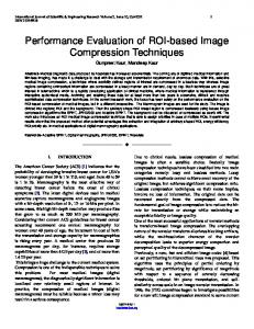
Fig. 1. Adaptive broadband MIMO system based on Turbo MIMO Equalization (TME)
I. INTRODUCTION Multiple-input multiple-output (MIMO) air interfaces based on antenna arrays at both the transmitter as well as the receiver side are shown to be a key technology for mobile internet and next generation wireless systems. The high bit rate required by these wireless links can only be reached with broadband MIMO systems. A low-complexity signal separation method which jointly exploits the spatial as well as the temporal structure of frequency selective MIMO channels was proposed in [1] and is called Turbo MIMO Equalizer (TME). In TME, the computational complexity of the minimum mean square error (MMSE) equalizer grows only in cubic order with the number receive antennas and the channel memory lengths, while for a maximum likelihood sequence estimation (MLSE) or maximum a-posteriori (MAP) detection the complexity increases exponentially. Recent research results [2] [3] have shown that the performance of TME schemes strongly depend on the multipath propagation characteristic. To provide a robust and reliable MIMO communication system under changing propagations condition an adaptive optimization regarding the antenna configuration (number of parallel transmissions as well as antenna selection), diversity concepts, channel coding, symbol modulation, etc. of the signal transmission over changing MIMO channels is required [4]. In this publication, we focus on antenna variable modulation for transmissions based on the TME. Two concepts for higher modulation and detection based on the turbo equalization namely bit interleaved coded modulation (BICM) [5] and multi-level bit interleaved coded modulation (MLBICM) [6] [7] are known. The later one showed superior robust transmission [4] [8] and is considered here for further analysis. The performances are assessed and compared using real-time MIMO measurement data. Channel sounding techniques provide the possibility to evaluate the performance of radio multiple access and signal processing schemes under realistic propagation conditions. Complex channel impulse responses (CIR) gathered through MIMO measurements in a real field scenario with different propagation characteristics have been used in link-level simulations. The identification of the multipath channel by means of high
resolution parameter estimation is essential for investigating the influence of the spatial and temporal structure on the performance of the TME. Therefore this paper employs the results of doubledirectional channel sounding experiments for MIMO link level simulations [9] [10]. II. ADAPTIVE SPACE TIME SIGNAL TRANSMISSION A. Transmitter/Receiver Configuration The system considered in this paper is based on the TME [1] and is extended regarding higher signal constellation following [6] to MLBICM. Furthermore the MIMO system concept supports different signal modulations for each transmit antenna. The block diagram of the system is shown in Fig. 1. The transmitter consists of an adaptive flow control and transmit modules, each for every antenna. An adaptive flow control is assumed to schedule the information bits in data streams, regarding the selected modulation. The coding&mapping / decoding&demapping blocks are shown in Fig. 2, which include the signal processing on the transmit as well as the receive side. The number of receive blocks are equal to the number of transmit blocks and each receive block is associated exactly to one transmit block. The transmission mode of a transmit block is determined through the receiver via a feedback channel. The transmitted multilevel coded signal of the k-th transmit block (Fig. 2a) is constructed as follows: At first, the information bits are demultiplexed into Mk parallel levels and convolutionally encoded. Next, the encoded bits are interleaved with different random interleavers and then BPSK-modulated. The resulting symbols of the different levels are grouped into sequences of Mk bits. The mapper can be seen as a linear combiner of the Mk BPSKmodulated symbols, so that each bit in a group is multiplied with a level-specific complex weighting factor zm and summed up into a QAM symbol. The complex weighting factor zm is real for odd m and imaginary for even m. Each transmitted QPSK symbol is then given by sk (n) = zTk · ck (n), (1)
Wireless Personal Multimedia Communications (WPMC ’04) , Abano Terme, Italy, 12th-15th of September 2004 where Z is a block diagonal matrix of the mapping row vectors zk . III. TURBO MIMO MLBICM EQUALIZATION FOR PER ANTENNA VARIABLE HIGHER MODULATIONS The Turbo MIMO equalizer for the MLBICM scheme is based on the concept presented in [6] with extensions to the MIMO case [4]. At first, on the basis of the available a-priori information from the SISO channel decoding, the first and second order statistics are computed for each level bit ck,m (n) as
(a)
c¯k,m (n) = E {ck,m (n)} = tanh (b)
where zk = [z1 , . . . , zm , . . . , zMk ]T is the stream specific mapping vector for antenna k with its levels being ordered by decreasing amplitude, and (2)
is the group of BPSK-modulated bits from the individual coding levels. The corresponding signal constellation consists of super positioned QPSK constellations [6]. For example, the mapping vector of a 16-QAM constellationp(two super positioned QPSK 2/5 [1, j, 0.5, 0.5j] T . Notice constellations) is given as zk = that the signal sets of the individual antennas can be different. In a turbo transmission system the multiple coded levels of a MLBICM scheme can be decoded in parallel without inter-decoder information exchange [6]. Hence, a MLBICM receive block (Fig. 2b) consists of Mk channel decoders, which work in parallel and in each case are separated by interleaving and de-interleaving. A channel decoder is always associated to exact one level of the proper transmit module. Because of the linear mapping a complex symbol-to-bit soft de-mapping generally required in equalization of high order modulation can be avoided. B. Signal Model The transmit symbols sk (n) are transmitted across a frequencyselective channel, which is assumed to be static over a frame duration and is perfectly known at the receiver. The radio channel between each pair of NR receive and NT transmit antennas is modeled by complex finite impulse responses hj,k (l) with L taps. The receive signal at antenna j can be represented as L−1 NT
rj (n) =
XX
hj,k (l) · sk (n − l) + σ0 vj (n),
λdk,m (n) 2
�
var {ck,m (n)} = 1 − c¯2k,m (n),
Fig. 2. (a) MLBICM coding and modulation, (b) MLBICM decoding, demodulation
ck (n) = [ck,1 (n), . . . , ck,m (n), . . . , ck,Mk ]T
�
(3)
l=0 k=1
where vj (n) is additive white Gaussian noise with unit variance. Furthermore, a compact matrix-vector notation of (3) can be written in the form r(n) = H · s(n) + σ0 v(n), (4)
(6) (7)
λdk,m (n)
where is the a-priori log likelihood feedback from decoder (k, m). The a-priori symbol mean in (6) is then utilized in the softcancellation of known signal components from the received signal vector [6]. The output of the soft-cancellation can be specified with (4)-(6) for each k and m as rˆk,m (n) = r(n) − H · Z · ¯ c(n) + zm hk · cˆk,m (n),
(8)
where the vector ¯ c(n) comprises all a-priori symbol means. For minimizing residual interferer components in (8), an instantaneous MMSE filter is applied. The filter output is given by cˆk,m (n) = wH ˆk,m (n). k,m (n) · r
(9)
To� compute the filter taps wk,m (n), the MMSE criterion E |ck,m (n) − cˆk,m (n)|2 is solved for each k and m. The solution to the MMSE optimization is shown to be wk,m (n) = αk,m (n) · uk,m (n),
(10)
where αk,m (n) = 1/ 1 + zm c¯2k,m (n) · uH k,m (n) · hk and
�
uk,m (n) = Σ−1 (n) · hk · zm .
(11) (12)
with Σ(n), the common covariance matrix of the residual signal as defined in [4]. Finally, the bit extrinsic likelihood information for the channel decoders are computed for each k and m as [8] λek,m (n) =
< {4ˆ ck,m (n)} 1 − µk,m (n)
(13)
with µk,m (n) = zm wH k,m (n) · hk .
(14)
IV. MEASUREMENT BASED REALISTIC SIMULATIONS A. Micro Cell Measurement and Channel Characterization
The MIMO measurement scenario under consideration can be classified as micro cell outdoor scenario for a wireless local area network (WLAN) application with low mobility. A sketch of the scenario is shown in Fig. 3. The place, a large courtyard at the campus of the Technische Universit¨at Ilmenau, is completely by introducing a space-time MIMO channel matrix H and receive enclosed by a building of about 15 m height. Furthermore, several and transmit space-time sample vectors r(n) and s(n), similar to various metal objects (container, mesh fence and tubes) were [1]. Additionally, the vectors hk are defined as located within the courtyard. An 8 element uniform linear antenna hk = [h1k (L − 1), . . . , hNR k (L − 1), . . . , h1k (0), . . . , hNR k (0)]T , (ULA) with separate ports for horizontal and vertical polarization was utilized on the receive side, whereby the antenna was mounted which are the NT central columns of the matrix H. As indicated by at a height of 1.67 m and only the vertical polarization was Equation (1), the block-partitioned signal constellation is treated measured. On the opposite a uniform circular array consisting of as a linear combination of binary sub-constellations. Hence, the 16 omnidirectional elements was fastened at a height of 2.10 m transmit space-time symbol vector in (4) can be expressed as [4] and moved at walking speed from position TX1 to TX2. All s(n) = Z · c(n), (5) measurements have been performed at 5.2 GHz carrier frequency
Wireless Personal Multimedia Communications (WPMC ’04) , Abano Terme, Italy, 12th-15th of September 2004
B. MIMO System Simulation Assumptions For simpleness - a MIMO system based on two transmit and two receive antennas was considered for all link level simulations. On each antenna as well as for each multilevel independent convolutionally encoding (K = 3, Rc = 0.5) and random block interleaving were processed. Every transmitted frame consists of 1024 information bits which are demultiplexed to the different antennas and levels. According to the assumptions from [2] the measurement data were selected and preprocessed for the target symbol rate of 20 Msym/s per antenna. Whereby for the pulse shaping a root-raised cosine filter (roll-off=0.25) was employed. The resulting channel impulse responses are modeled, corresponding to the delay components observed within the measurement data, using 24 delay taps. At the receiver with L = 9 temporal taps, we performed the signal separation. This is sufficient to capture the significant part of the received energy within the channel impulse responses. In principle the problem of transmit power and signal to noise ratio (SNR) definition can be seen from different viewing angles, in particular if the transition between NLOS and LOS for MIMO system evaluation is considered. In this paper, the goal is to analyze the performance with changing multipath structure, consequently a constant transmit power and subsequently path loss influences are not in the focus here. Therefore the SNR at the receiver is held constant and identical for each transmitted information bit by an adaptive power control.
40
120 LOS dyn.
NLOS dyn.
30 TX
80 NLOS stat.
20
60
40
RMS Tx azimuth spread [°]
100 RMS Rx azimuth spread [°]
and with a bandwidth of 120 MHz. The measurement track can be separated into three parts, where different multipath characteristics were found. Here the spatial channel properties are highlighted in terms of root mean square (RMS) Rx and Tx azimuth spreads (direction of arrival and direction of departure), see Fig. 4. A continuative identification of multiple path components can be found in [3]. In the beginning of the measurement the transmitter was not moving, at this point a rich multipath diversity with RMS Tx spreads around 100◦ were found. Starting from TX1 the transmitter moved under NLOS (Non-Line-Of-Sight) condition for approx. 3 m. In the mean the Tx spreads vary around 60◦ 70◦ , which indicates medium multipath diversity. Whereby the Rx spreads for both NLOS parts (stat. and dyn.) are considerable lower (mean of 15◦ ) due to the limited view of the ULA (+/- 60◦ regarding to the antenna look direction). For the rest of the track transmitter and receiver had line of sight (LOS), here naturally the spread values are significantly lower compared to the NLOS cases. These three different propagation characteristics (NLOS stationary, NLOS dynamic and LOS dynamic) are considered in the subsequent performance evaluation section.
10 20
RX
0 1
Fig. 4. track
40
80 120 Measurement Position #
0 201
160
RMS Tx and Rx azimuth spread along the entire measurement
Fig. 5 shows the resulting normalized transmit power per antenna, whereby at both antennas the same modulation is assumed. With adaptive modulation per transmit antenna different symbol to noise ratios according to the aforementioned understanding would result. Furthermore the total transmitted power is independent on the numbers of transmit antennas. Considering this assumptions we are able to compare in a transparent way the link performance in terms of frame error rates (FER) and subsequently the throughput efficiency (TP) for MIMO systems with variable modulations per antenna. V. RESULTS OF THE REALISTIC MIMO SIMULATIONS The aim of this paper is to study the TP given by the proposed broadband MIMO system in channels with changing multipath characteristics. The question arises: Which adaptation on the transmit signal processing is necessary to guarantee the highest throughput by a reliable and robust transmission? Here the signal modulation can be changed independently for each antenna chosen between QPSK and 16-QAM. No specific parameter is considered for adaptive control of the modulation scheme, hence the focus is on its potential impact. In the Fig. 6 the FER versus the SNR after 6 iterations of the 2x2 TME with 16-QAM at both antennas is shown. It is obvious that the performance for separation of both signals strongly depends on the multipath diversity within the channel, as indicated by the RMS Tx and Rx azimuth spreads for the particular regions, see Fig. 4. In channels with considerably high spatial and temporal
35 antenna 1 antenna 2 30
normalized Tx Power [dB]
25 20 15 10 5 0 −5
Fig. 3.
Measurement Scenario
20
40
60
80 100 120 140 Measurement Position #
160
180
201
Fig. 5. Normalized transmit power for same modulation at both antennas
Wireless Personal Multimedia Communications (WPMC ’04) , Abano Terme, Italy, 12th-15th of September 2004 10
0
NLOS stat. NLOS dyn. LOS Average
FER
10
10
−1
−2
Layer 1
10
10
Layer 2
−3
−4
0
2
4
6
8 10 SNR [dB]
12
14
16
18
Fig. 6. FER curves for 2/2 TME based on MLBICM with 16-QAM within static NLOS, dynamic NLOS and LOS regions
diversity (NLOS stat.) the receiver is feasible to detect the two 16QAM signals easily. With moving transmitter under NLOS dyn. and further LOS conditions the performance suffers more and more. This effect can be seen in both layer 1 and layer 2 of the 16-QAM MLBICM signal. In total, the layer 2 has higher FER due to the unequal error protection property of the MLBICM concept [6]. Based on the FER results the TP can be analysed, which is defined [12] as, TP = Rc (1-FER) (15) where selective-repeat ARQ with infinite buffering is assumed. This leads to a maximum throughput efficiency of 0.5 and a corresponding maximum data rate of 80 Mbits/s. During the simulation the measurement track was covered by 201 snapshots, whereby for each snapshot 7000 frames were transmitted. Fig. 7 highlights the high dependency of the averaged TP from the particular propagation phenomena, where both antennas (2x2 TME) always transmit 16-QAM signals. Here a single ARQ controller is assumed which takes care of the re-transmission - the whole frame is retransmitted in case of frame errors. This approach is considered as S-ARQ in the sequel to indicate the single ARQ controller. However the retransmission probability and the resulting TP of MLBICM is dominated by errors from layer 2. This can be avoided, if the re-transmission is controlled independently from each layer by two separated ARQs, hence the overall TP is improved [8].
Due to the layer structure of the MLBICM this concept will be called layered ARQ (L-ARQ) [8]. In Fig. 8 the average TP over all snapshots along the entire measurement track with S-ARQ and L-ARQ is displayed. For the latter the TP performance for each layer can be assessed, whereby the total TP is the sum of the results from both layers, hence leads to better performance compared to S-ARQ. Exactly the same behaviour was found for the MIMO transmission with QPSK and 16-QAM on transmit antenna 1 and 2 respectively (total data rate of 60 Mbits/s), see Fig. 8. Compared to the case with 16-QAM at both antennas the TP is normalized, hence the maximal TP is 0.375. However the QPSK/16-QAM case reaches higher values for lower SNRs. Furthermore it indicates that under dominating LOS influence the modulation has to be switched to lower constellation, indeed only at one antenna. Fig. 9 splits those results into the different propagation regions. Again in comparison with Fig. 7 the L-ARQ for 16-QAM/16-QAM shows in all cases clearly better results. For further examination only the superior L-ARQ is considered. Continuing the TP analysis the complementary cumulative distribution function (CCDF) for the antenna variable modulation is examined. Results based on the CCDF will emphasis the reliability and confidence on the selected antenna variable modulation. Therefore, in this paper we assume to ensure reliable and robust MIMO transmission the target TP area to be appear in 90% and more of all cases. Hence, if the probability of a particular modulation per antenna setup becomes lower as this threshold the transmitter has to switch the modulation at the antennas to the highest possible by keeping this constraint. As example we calculate the CCDF at 8dB SNR, see Fig. 10. It was found that in the L-ARQ case only under rich multipath characteristic (NLOS stat.) the threshold can be hold for the 16-QAM at both antennas. For NLOS dyn. and LOS the transmitter must send with QPSK and 16-QAM at the two antennas to guarantee the 90% confidence for the highest throughput. However the decision for adaptive switching based on the CCDF is different compared to the one based on the TP calculation for NLOS dyn. shown in Fig. 9. In the latter case only the mean performance at each SNR point is highlighted and hence gives lower confidence. The CCDF results show that antenna variable modulation and L-ARQ through channels with different multipath diversity can assure the reliability of the MIMO transmission. The prior analysis within this paper considered the switching between two different modulation setups on the transmit antennas for the three different regions, but fixed within them. By introducing an adaptive switching for each measurement position the
0.5
0.5
Average Throughput Efficiency
0.4
0.45 0.4 Average Throughput Efficiency
0.45
NLOS stat. NLOS dyn. LOS Average
0.35 0.3 0.25 0.2 0.15
0.3 0.25
0.15 0.1 0.05
4
6
8 10 SNR [dB]
12
14
16
18
Fig. 7. Average throughput efficiency for 16-QAM on both antennas and S-ARQ within static NLOS, dynamic NLOS and LOS regions
Tx1: QPSK Tx2: 16−QAM
0.2
0.1
2
Tx1: 16−QAM Tx2: 16−QAM
0.35
0.05 0 0
Layer 1 Layer 2 L−ARQ S−ARQ
0 0
2
4
6
8 10 SNR [dB]
12
14
16
18
Fig. 8. Average throughput efficiency L-ARQ and S-ARQ, 16-QAM/16QAM and QPSK/16-QAM, all snapshots
Wireless Personal Multimedia Communications (WPMC ’04) , Abano Terme, Italy, 12th-15th of September 2004 0.5
Average Throughput Efficiency
0.4
0.45 0.4 Average Throughput Efficiency
0.45
0.5 NLOS stat. NLOS dyn. LOS Average
0.35 0.3
Tx1: QPSK Tx2: 16−QAM
0.25 0.2 0.15
Tx1: 16−QAM Tx2: 16−QAM
0.35 0.3 0.25 0.2 0.15
0.1
0.1
0.05
0.05
0 0
2
4
6
8 10 SNR [dB]
12
14
16
18
NLOS stat. NLOS dyn. LOS Average
0 0
2
4
6
8 10 SNR [dB]
12
14
16
18
Fig. 9. Average throughput efficiency for L-ARQ, 16-QAM/16-QAM and QPSK/16-QAM, within static NLOS, dynamic NLOS and LOS regions
Fig. 11. Average maximum throughput efficiency for L-ARQ, within static NLOS, dynamic NLOS and LOS regions
maximum TP can be assessed. For each position and each SNR the modulation setup with the highest TP was selected. Fig. 11 highlights the performances again for the regions with different multipath diversity and in average for the entire track. Obviously only tight improvements can be gained for the adaptive switching at each position. It seems that in this particular example a fixed swichting over positions with approximately similar propagation conditions will almost reach maximum TP, which leads to a slower adaptation scheme.
In continuation of the research within this paper the derivation of proper control parameter (e.g. spatial correlation) for link adaptation will play an important role. By using a feedback link the transmitter can be controlled by the receiver based on the channel/link properties. Combined with this also smart and low complexity adaptation algorithms/strategies are necessary. Moreover, the adaptive coding and antenna selection jointly with variable modulation schemes is seen to be a hot topic for research. Future work will also cover scalability in terms of parallel users/data streams for the spatial multiplexing MIMO concepts. In particular in channels with strong LOS components and/or low multipath diversity it could play an important role for performance optimization. Furthermore it can be expected that cross-layer issues regarding the joint optimization, e.g. for physical and media access layer, will become important for future designs.
VI. C ONCLUSIONS The throughput performance of the analysed TME strongly depends on the multipath characteristic within the broadband MIMO channel. Under low spatial and temporal diversity as well as propagation phenomena dominated by LOS components the spatial multiplexing MIMO systems suffers. By using variable modulation per antenna, the robustness and reliability of the MIMO transmission can be significantly improved. Furthermore by adopting the ARQ to the properties of the physical layer a superior performance has been highlighted. MIMO measurement trials combined with high-resolution channel characterization provide detailed insights into the physical propagation conditions in different real world scenarios. Using these methods the performance of the candidate MIMO concepts can be realistically evaluated and interpreted. 1 0.9 0.8 0.7 Tx1: QPSK Tx2: 16−QAM
CCDF
0.6 0.5 0.4 0.3 0.2 0.1 0 0
NLOS stat. NLOS dyn. LOS Average 0.1
Tx1: 16−QAM Tx2: 16−QAM
0.2
0.3
Throughput @ 8 dB
0.4
0.5
Fig. 10. CCDF for TP with different modulations and L-ARQ, within static NLOS, dynamic NLOS and LOS regions
R EFERENCES [1] T. Abe and T. Matsumoto, “Space-Time Turbo Equalization in Frequency-Selective MIMO Channels”, IEEE Trans. Veh. Technol., vol. 52, no. 3, pp. 469-475, May 2003. [2] U. Trautwein, T. Matsumoto, C. Schneider, R.S. Thomae, “Exploring the Performance of Turbo MIMO Equalization in Real Field Scenarios”, WPMC 2002, October 27-30, Honolulu, Hawaii. [3] C. Schneider, R.S. Thoma; U. Trautwein, T. Matsumoto, “The Dependency of Turbo MIMO Equalizer Performance on the Spatial and Temporal Multipath Channel Structure”, IEEE VTC2002-Spring, April 21-24, Jeju, Korea. [4] C. Schneider, M. Grossmann, R.S. Thoma, “Performance of Antenna Variable Modulation for Turbo MIMO Transmission in FrequencySelective Channels”, Proceedings ITG Workshop on Smart Antennas, March 2004, Munich, Germany. [5] G. Caire, G. Taricco, and E. Biglieri, “Bit-interleaved coded modulation”, IEEE Trans. Inform. Theory, vol. 44, pp. 927-946, May 1998. [6] K. Kansanen and T. Matsumoto, “Turbo Equalization of Multilevel Coded QAM”, Conf. Rec. SPAWC03, June 2003, Rome, Italy. [7] U. Wachsmann, R. Fischer, J. Huber, “Multilevel codes: theoretical concepts and practical design rules”, IEEE Trans. Inform. Theory, Vol. 45, no. 5, pp. 1361-1391, July 1994. [8] K. Kansanen, C. Schneider, T. Matsumoto, R. Thoma, “Multilevel Coded QAM with MIMO Turbo-Equalization in Broadband SingleCarrier Signalling”, submitted to IEEE Trans. Veh. Technol., 2004. [9] R. S. Thoma, D. Hampicke, A. Richter, G. Sommerkorn, U. Trautwein, “MIMO Vector Channel Sounder Measurement for Smart Antenna System Evaluation”, European Trans. on Telecomm., ETT Vol. 12, No. 5, Sept./Oct. 2001 [10] http://www.channelsounder.de [11] M. Tuechler, A. C. Singer, and R. Koetter, “Minimum mean squared error equalisation using a priori information”, IEEE Trans. Signal Processing, vol. 50, no. 3, pp. 673-683, Mar. 2002. [12] S. Lin and D. Costello, Error Control Coding Englewood Cliffs, NJ, USA: Prentice-Hall, 1983.