Measurement of the transient shielding effectiveness of enclosures ...
Recommend Documents
Measurement of SE with the Image Theory. Analyzer. Network. Antenna. Chamber. E.U.T. ... 2.3 Equivalent use of spectrum or network analyzer. For this type of ..... Penetration Through Apertures: FDTD Versus Measurements,. IEEE Trans. on ...
2 Oct 2016 - size of enclosure, aperture size, aperture shape, configuration and number ... of Electromagnetic Shielding Enclosures) [2] is generally used to ...
May 15, 2017 - In this paper, an efficient domain decomposition mesh-free method (DD-MFM) is introduced to analyze the shielding effectiveness of a ...
oped using a double yoke; one a magnetizing yoke and the other a sensing yoke. Using the .... [1] J. L. Norman Violette, D. R. J. White, and M. F Violette,.
was used to transmit a microwave signal. It was covered ... an Agilent E8257D microwave generator, which ... antenna, generator and computer were located.
Aug 1, 2018 - In RF dielectric heating application, two most applicable wave ... Most common dielectric heating applications are microwave and radio ...
Min Li, Joe Nuebel, Member, IEEE, James L. Drewniak, Member, IEEE, Richard E. DuBroff, Senior Member, IEEE,. Todd H. Hubing, Senior Member, IEEE, and ...
AbstractâElectromagnetic interference (EMI) from slots and apertures resulting from coupling of interior sources through enclosure cavity modes in a ...
The sintering was performed at 700 °C under 2 MPa of pressure for 6 h. The micro- .... formed with a JEOL JSM-5600 model scanning electron microscope (SEM) .... 11 C. T. Wei, V. F. Nesterenko, T. P. Weihs, B. A. Remington, H. S.. Park, M. A. ...
Oct 12, 2016 - Shields have traditionally been constructed from metals and metal ... Additionally, it is often desirable for a shield to absorb a large amount of ...
Jul 16, 2012 - shield the enclosure holding the equipment with commercial EMC shields. However, such are often deemed too expensive and thus critical.
Apr 6, 2011 - RTV Silicone Rubber Filled with Carbon Black,â Journal of Functional Polymers, Vol. 18, No. 2, 2005, pp. 227-231. [10] P. Li, S. Liu and G. Chen ...
Abstract. We propose a new convenient material shield- ing effectiveness measurement method based on a skin-effect transmission line coupler. The method is ...
shielding effectiveness consists in absorbing EMR as a result of so-called multiple internal reflection. Methods for ..... signed to the requirements resulting from.
especially after electroplating with nickel. ... made by electroplating, electroless plating or vacuum ..... of aluminum on plastic parts for EMI shielding, Albuquer-.
measured for samples by VNA analysis and shielding effectiveness was calculated for them that the maximum ... E-mail address: [email protected].
measure of the efficiency of an enclosure is the shielding effectiveness (SEe), i.e. the ability of attenuating the sources of electromagnetic disturbance. Usually ...
Feb 25, 2016 - Shielding Effectiveness Simulation of Small .... computed using Equations (8)â(11) by the software COMSOL ..... Electromagnetic Shielding, for Electronic Test Purposes; U.S. Government Printing Office: Washington, DC,.
The measurements can be made by using a signal source and a receiver like an oscilloscope or a spectrum analyser, or by using a vector network analyser.
Measurement set-up for shielding effectiveness characterization. The shielding effectiveness, SE, describes the performance of the shield and it is defined as [5]:.
Modeling. Min Li, Joe Nuebel, Member, IEEE, James L. Drewniak, Member, IEEE, Richard E. DuBroff, Senior Member, IEEE,. Todd H. Hubing, Senior Member, ...
effectiveness and suggests benefits. Keywords: ... spending in order to achieve a good results in short-term and long-term period. Introduction of .... ABC method is not primarily selected to measure the effectiveness of a marketing activity. ... nec
Apr 29, 2004 - and cotton as the sheath using the Dref-3 friction spinning system. A special guide mechanism was designed and used to produce a uniform ...
Measurement of the transient shielding effectiveness of enclosures ...
using UWB pulses inside an open TEM waveguide. H. Herlemann and M. Koch. University of Hannover, Institute of Electrical Engineering and Measurement ...
Measurement of the transient shielding effectiveness of enclosures using UWB pulses inside an open TEM waveguide H. Herlemann and M. Koch University of Hannover, Institute of Electrical Engineering and Measurement Science, Hannover, Germany
Abstract. Recently, new definitions of shielding effectiveness (SE) for high-frequency and transient electromagnetic fields were introduced by Klinkenbusch (2005). Numerical results were shown for closed as well as for non closed cylindrical shields. In the present work, a measurement procedure is introduced using ultra wideband (UWB) electromagnetic field pulses. The procedure provides a quick way to determine the transient shielding effectiveness of an enclosure without performing time consuming frequency domain measurements. For demonstration, a cylindrical enclosure made of conductive textile is examined. The field pulses are generated inside an open TEM-waveguide. From the measurement of the transient electric and magnetic fields with and without the shield in place, the electric and magnetic shielding effectiveness of the shielding material as well as the transient shielding effectiveness of the enclosure are derived.
1
Introduction
The question of how to determine the protective properties of a shield against electromagnetic disturbances is a difficult one to be addressed, even in frequency domain. According to conventional standard measurement procedures (IEEE Standard 299-1997), only the electric- or magnetic shielding effectiveness (SE) of the empty shield is measured. Since the shield usually forms a cavity resonator with internal resonances, the shielding effectiveness breaks down at the cavity’s characteristic resonance frequencies. In addition, it becomes a function of position. The effects on the behaviour of the SE when a filling (e.g. a printed circuit board, PCB, inside a small enclosure) is present are even less predictable since on the one hand part of the electromagnetic energy is absorbed and on the other hand, there are numerous coupling paths into the electronic equipment. As was shown by Marvin et al. (2004, 2005), the reduction in absorbed power inside the filling when the shield is applied is less over most Correspondence to: H. Herlemann ([email protected])
of the frequencies, than the SE value indicates. It was found out, that the conventional SE value of the empty shield exhibits an overestimate concerning the absorbed power at all but the resonance frequencies. The authors suggested a test setup where the shield is loaded with a replacement content that represents the original content (i.e. PCB) by having same dimensions and electrical material parameters. A different approach to determine the protection properties of a loaded shield was introduced by Camp et al. (2004). Concerning the susceptibility of electronic equipment against transient electromagnetic fields, the authors suggested to determine the decrease of the breakdown probability of electronic equipment when the shield is applied. It is a statistical approach. Whereas the mentioned authors introduced measurement procedures with loaded enclosures, Klinkenbusch (2005) suggested measurements of the empty shield from which the effect of the shield on the specific absorption rate (SAR) of the filling is calculated. The two analytically developed measures introduced by Klinkenbusch are namely the electromagnetic shielding effectiveness SEem in the frequency domain and the transient shielding effectiveness SEt in the time domain. SEem is a function of frequency and SEt is a function of the specific field pulse against which the shield’s protective property is examined (e.g. electrostatic discharge, ESD, high power microwave, HPM, ultra wide band (UWB) pulses). In this contribution, a time domain measurement technique for the determination of the transient shielding effectiveness is presented, where the enclosure under test (EUT) is exposed to transient fields. This approach is based on the fact, that the SE of an enclosure can either be determined directly by means of measurements in the frequency domain or indirectly by means of performing fast Fourier transformations (FFT) on recorded transient field data. Frequency domain measurements exhibit a greater accuracy and dynamic range but they are time consuming, since a frequency domain sweep has to be performed. In addition, various antennas, amplifiers and receivers have to be used in order to perform measurements along an ultra wide frequency range.
Published by Copernicus Publications on behalf of the URSI Landesausschuss in der Bundesrepublik Deutschland e.V.
76
H. Herlemann and M. Koch: Measurement of the transient shielding effectiveness of enclosures l y
x
PulsGenerator
z
×
EUT
h
Septum TEM-waveguide
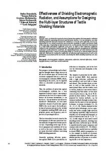
Figure 2. Pouch made of conductive textile. Fig. 2. Pouch made of conductive textile.
Oscilloscope
Fig. 1. Setup for measurements of transient fields inside TEM-
Figure 1. Setup for measurements of transient fields inside TEM-waveguide. waveguide.
The transient shielding effectiveness is defined by the expression Shielding Effectiveness of plane conductive textile with size 2 x 2 m
SEt |q =
limit 120
Table 1. Measurement Equipment. Pulse Generator :
Kentech: PBG3
tr =100 ps, tFWHM =2.5 ns
˙ D-Sensor: ˙ Balun for D: ˙ B-Sensor: ˙ Balun for B: Oscilloscope:
Definition of the transient shielding effectiveness
The transient shielding effectiveness introduced by Klinkenbusch (2005) is analytically derived from the examination of the ratio of electromagnetic energy absorbed by an unshielded load to that one absorbed by the shielded load for the same incident field at the limiting case that the load vanishes. It is based on the conventional measurement of the electric and magnetic SE at an arbitrary point q inside an empty enclosure: unshielded E q SEe |q = 20 log10 shielded dB (1) E q
SEm |q = 20 log10
q
Adv. Radio Sci., 5, 75–79, 2007
6000
800
(3)
SE / dB
SE / dB
fg =6 GHz, 20 GS/s
20
unshielded H q dB H shielded
vertic
where S inc60(ω) denotes the spectral density distribution of an 60 arbitrary transient plane wave and ω denotes the angular frequency. It 40 is a single value for a given or assumptive incident 40 field pulse.
Especially in the case of small enclosures, the size of common antennas for EMC applications does not allow measurements inside the shield. In contrast, transient measurements exhibit less dynamic range but they are quicker, since only one measurement setup is needed for the whole frequency spectrum of the used pulse. This contribution is divided into 5 sections. After this introduction, the needed definitions of the transient shielding effectiveness are given in Sect. 2. The measurement setup is presented in Sect. 3 and the post processing of the data for the evaluation of SEt is explained in Sect. 4. 2
horizontal
120
2 R∞ 2 S inc (ω) ωdω
(2)
3
20
Measurement setup 0 0
200
0
400 600 f / MHz
800
1000
2000
4000
The measurement setup (Fig. 1) consists of an open tri f / MHz plate TEM-waveguide (l≈5.8 m, h≈2 m) which is basically aFigure GTEM-cell without side walls. The septum is connected 3. Shielding effectiveness of the pouch’s conductive textile. to the back wall by a network of resistors that ensures that the waveguide is matched with its characteristic wave impedance. For the high frequency match, pyramidal absorbers are placed on the back wall. The waveguide is fed by a 12 pulse generator that generates voltage pulses of about 100 ps rise time. For the detection of the transient electric ˙ sensor, a B-dot (B) ˙ sensor and magnetic fields, a D-dot (D) and a fast sampling oscilloscope are used (see Table 1 for details). The EUT is a cylindrical pouch made of conductive textile similar to the one depicted in Fig. 2. The pouch is made of two layers of conductive textile, it has got a length of approx. 83 cm and a diameter of approx. 36 cm and was originally designed for the electromagnetic protection of ordnance during transport and storage as presented by Koch et al. (2003). The shielding effectiveness of a 2 by 2 m plane sample of this textile was measured to be above 50 dB (with only few exceptions) for frequencies from 75 MHz up to 10 GHz (see Fig. 3). These measurements were carried out according to IEEE Std. 299-1997 (IEEE, 1997) in the measurement setup described by Frenzel et al. (2007). During the particular transient measurements for this work, the pouch was positioned along the x-direction about www.adv-radio-sci.net/5/75/2007/
H. Herlemann and M. Koch: Measurement of the transient shielding effectiveness of enclosures
77
Shielding Effectiveness of plane conductive textile with size 2 x 2 m
120
100
100
80
80
SE / dB
SE / dB
limit 120
60
40
20
20
0
0 200
400 600 f / MHz
800
vertical
6000 f / MHz
8000
60
40
0
horizontal
1000
2000
4000
10000
Fig. 3. Shielding effectiveness of the pouch’s conductive textile.
Figure 3. Shielding effectiveness of the pouch’s conductive textile. r
Calculation of detected field strength from the sensor output voltage
The detected electric field strength was calculated from the recorded output voltage signal of the sensor by means of an integration: the D-dot sensor’s output voltage U (t) is proportional to the derivative of the D-field according to ∂D (t) U (t) = R · Aeq · . (4) ∂t In this case, R is the impedance of the sensor’s output port and Aeq is its equivalent sensor-surface. Using the mathematical relation between the D-field and the E-field in free space according to Eq. (4) can be rewritten as Z 1 E (t) = · U (t) dt. R · Aeq · ε0 www.adv-radio-sci.net/5/75/2007/
H / (A/m)
Einc
5 0
r
(5)
(6)
Hinc
10 0 -10 0
20 30 t / ns t =1700ps, t =5450ps
fwhm
10
r
shielded
200 400 600 800 t / ns
=550ps
fwhm
20
10
E
r
30
H / (A/m)
0.4 0.3 0.2 0.1 0 -0.1 -0.2 -0.3
0
D (t) = ε0 · E (t) ,
t =250ps, t 40
20 30 t / ns t =550ps, t =12250ps
Since the oscilloscope records the sensor’s output voltage, which is influenced by the sensor’s (and the balun’s and the cable’s) transfer function, the detected field strength has to be calculated from the recorded data. Afterwards, the transient shielding effectiveness can be calculated. 4.1
=450ps
fwhm
10
-5 0
Data processing E / (kV/m)
4
t =150ps, t 15 E / (kV/m)
30 cm above the waveguide’s floor. Thus, the field components Ey and Hx were measured and processed later on. The Oscilloscope was set to single trigger event mode. The recorded electric and magnetic transient field in the unshielded and shielded case are depicted in Fig. 4.
fwhm
Hshielded
3 2 1 0 -1 -2 0
13 100
200 300 t / ns
400
Figure field pulses; electric field: left column, field: right column, Fig.4.4.Measured Measured field pulses; electric field:magnetic left column, magnetic unshielded: uppercolumn, row, shielded: lower row. upper field: right unshielded:
row, shielded: lower row.
The integration was performed numerically by means of calculating the sum of the saved digital data. In order to take account for the influence of the Balun and the cabeling on the received signal, their attenuation was determined with a spectrum analyzer in a first approach. The measured values at 1 GHz were chosen for a correction calculation. A network analysis of the cabeling was omitted. 4.2
Calculation of transient shielding effectiveness
SEe and SEm are determined according to Eqs. (1) and (2) by means of an FFT on the measured time domain field strength values (shown in Fig. 4). The results are depicted in Fig. 5. Adv. Radio Sci., 5, 75–79, 2007
14
78
H. Herlemann and M. Koch: Measurement of the transient shielding effectiveness of enclosures Electric Shielding Effectiveness
110
100
80
80
70 SEm / dB
90
90 SEe / dB
100
70 60 50
60 50 40
40
30
30
20
20 0
0.5
1
f / GHz
10 0
1.5
Magnetic Shielding Effectiveness
0.5
1
f / GHz
1.5
Figure 5. Calculated electric (left) and magnetic (right) shielding effectiveness of the pouch Fig. 5. Calculated electric (left) and magnetic (right) shielding effectiveness of the pouch from the transient measurements by means of FFT.
from the transient measurements by means of FFT.
FFT
Eshielded (t)
FFT
Eunshielded (t) Sinc (t) = E(t) × H(t) shielded
E
H
(t)
unshielded
(t)
FFT
FFT
Hshielded (t)
inc
S (t) = E(t) × H(t) Fig. 6. Flowchart of postprocessing. unshielded Figure 6. Flowchart of postprocessing.
(t)
2 inc
5
10
ω / rad
9
x 10 Denominator of SE : ∫ ... dω ′ 23 t 0 x 10 4 ω
2 1 5
ω / rad
39 38 37 0
5
ω / rad
10 9
x 10 10 log (Numerator/Denominator)
SEt / dB
3
0 0
41
Figure 6. Flowchart of postprocessing. 40
S
7 6 5 4 3 2 1 0 0
/ (dB(VA/m ))
Hshielded (t) Numerator of SE : 2 ⋅ ∫ω ... dω ′ Spectral density distribution 27 t 0 x 10 42
45 40 35 30 25 20 15
10 9 x 10
0
5
ω / rad
10 9 x 10
Figure 7. Intermediate results during the calculation of the transient shielding effectiveness.
Fig. 7. Intermediate results during the calculation of the transient shielding effectiveness.
In general, these results are comparable to those in Fig. 3. The strong ripples result from resonance effects of higher order modes. These modes are excited inside the pouch by the transient pulse event. In time domain, this effect causes the characteristic damped “ringing” that can be recognized in the Adv. Radio Sci., 5, 75–79, 2007
Eunshielded (ω)
FFT FFT
FFT
Eunshielded (t)
H
Eshielded (ω)
Sinc (ω) shielded
E
H
(ω)
unshielded
Hshielded (ω)
FFT
S (ω)
FFT
Hunshielded(ω)
inc
FFT
(ω)
Eunshielded (ω)
shielded
H measurements (ω) results of the shielded (Fig. 4, bottom). The fact, that SEe →∞ and SEm →0 for f →0 complies with the general theory of the behaviour of the shielding effectiveness of shields with limited conductivity as analysed by Klinkenbusch (2005). For the evaluation of the pouch’s transient shielding effectiveness against a specific plane wave field pulse according to Eq. (3), the pulse’s spectral density distribution is needed. At this point, any electromagnetic pulse could be taken, as long as the upper frequency of its spectral density distribution is below the upper frequency of shielding effectiveness measurements (i.e. 1.5 GHz in the present case). For convenience, SEt shall be evaluated for the test pulse. Therefore, the five values E shielded (ω), E unshielded (ω), H shielded (ω), H unshielded (ω) and S inc (ω), which are needed for Eq. (3), are determined according to the flow chart in 15 Fig. 6. Since the result of Eq. (3) is only a single value, some intermediate results of the numerical processing are presented in Fig. 7: the upper right hand diagram shows S inc (ω). On the left hand side, the numerator and denominator of Eq. (3) are presented. In order to show a graph, the upper boundary of the integral was changed into the variable angular frequency ω:
2 Rω – Numerator: 2 S inc (ω0 ) ω0 dω0 0
www.adv-radio-sci.net/5/75/2007/
H. Herlemann and M. Koch: Measurement of the transient shielding effectiveness of enclosures Rω – Denominator: S inc (ω0 ) 2 0
"
shielded 2 E
q 2 E unshielded q
|
|
+
shielded 2 H
q 2 H unshielded q
|
|
# ω0 dω0
The logarithmic ratio of numerator and denominator at each angular frequency is shown in the bottom right hand diagram. Since the integration boundaries in Eq. (3) are from zero to infinity, the result is the function value at the highest angular frequency. As a result, the question of the transient shielding effectiveness of the pouch against an UWB pulse of double exponential character with a rise time of 150 ps is 42 dB. 5
Conclusions
Transient field measurements have been performed inside an open TEM-waveguide in order to realize a quick measurement procedure for the evaluation of the transient shielding effectiveness, that has been introduced by Klinkenbusch (2005). For the measurements, a cylindrical pouch made of conductive textile was examined. The pouch was exposed to ultra wideband pulses of double exponential character with a rise time of about 150 ps. The Ey and Hx field components were recorded at the same position inside the TEMwaveguide with and without the shield around. Whereas the plane material of the pouch exhibits a shielding effectiveness of above 50 dB up to 10 GHz, the transient shielding effectiveness comes up with the answer 42 dB. Even though transient field measurements have the disadvantage of less dynamic range in comparison to frequency domain measurements, they contain the advantage of quick measurement procedures, where only one set of measurement equipment is needed.
www.adv-radio-sci.net/5/75/2007/
79
Acknowledgements. The authors like to thank the Scientific Institute for Protection Technologies/EMP-Protection (WIS) as well as the Technical Center for Information Technology and Electronics/Electromagnetic Effects/EMC (WTD81), both being part of the German Armed Forces, for providing the needed measurement facilities.
References Frenzel, T., Stumpf, J., and Koch, M.: Shielding effectiveness of original and modified building materials, Adv. Radio Sci., in press, 2007. Herlemann, H., Koch, M., Camp, M., Bausen, A., and Sabath, F.: Measurement of Protection Properties of Closed Shields in Time Domain, EMC York 2004 International Conference and Exhibition, York, England, 2004. IEEE Standard 299-1997 for Measuring the Effectiveness of Electromagnetic Shielding Enclosures, 1997. Klinkenbusch, L.: On the Shielding Effectiveness of Enclosures, IEEE Transactions on EMC, vol. 47, no. 3, 589–601, August, 2005. Koch, M., Zappe, W., and Camp, M.: The Safety of Ordnance in High Intensity Electromagnetic Fields, IEEE International Symposium on Electromagnetic Compatibility, Turkey, Istanbul, 2003. Marvin, A. C., Dawson, J. F., and Dawson, L.: New developments in shielding effectiveness measurements – shielding aperture, New EMC Issues in Design: Techniques, Tools and Components Seminar, The IEE, pp. 45–50, 28 April, 2004. Marvin, A. C., Dawson J. F., Ward, S., Dawson, L., Clegg, J., and Weissenfeld, A.: A Proposed New Definition and Measurement of the Shielding Effect of Equipment Enclosures, IEEE Transactions on EMC, vol. 47, no. 3, 589–601, August, 2005.