Measuring the Effort for Creating and Using Domain-Specific Models Yali Wu, Frank Hernandez, Francisco Ortega and Peter J. Clarke
Robert France Department of Computer Science Colorado State University Fort Collins, CO 80532, USA
School of Computing and Information Sciences Florida International University Miami, FL 33173, USA
[email protected]
{ywu001, fhern006, forte007, clarkep}@cs.fiu.edu
ABSTRACT The use of domain-specific modeling languages (DSMLs) results in higher productivity during the development process. This is accomplished by raising the level of abstraction during design and focusing on domain concepts rather than low-level implementation details. Unlike other development paradigms, little work has been done in determining and measuring the claimed benefits of using DSMLs. In this paper, we propose a new approach to determine the effort involved in creating and using DSML models to develop applications and to manage the behavior of applications at runtime. The approach involves a classification of the effort involved, and definition of relevant metrics to measure the effort for each category. A case study is presented that shows how we applied the proposed metrics during the development and execution of an application using three different DSMLs.
Categories and Subject Descriptors D.2.8 [Software Engineering]: Metrics—complexity measures, performance measures
General Terms Languages, Experimentation
Keywords Domain-specific modeling, metrics, effort
1.
INTRODUCTION
During the last decade the use of domain-specific modeling languages (DSMLs), has grown in both academia and industry. DSMLs are not only used to create development models, but also used to produce runtime models that users can use to manage runtime behavior. It is believed that
Permission to make digital or hard copies of all or part of this work for personal or classroom use is granted without fee provided that copies are not made or distributed for profit or commercial advantage and that copies bear this notice and the full citation on the first page. To copy otherwise, to republish, to post on servers or to redistribute to lists, requires prior specific permission and/or a fee. DSM:10 17-OCT-2010, Reno, USA Copyright 2010 ACM 978-1-4503-0549-5/10/10 ...$10.00.
these languages lead to an increase in productivity, and contribute to the production of models that are more flexible and easier to use than models produced using generalpurpose modeling languages (GPMLs) [21]. As modeling becomes more prevalent in the software development process, a spectrum of DSMLs have emerged with varying degrees of “domain-specificity”, expressive power and execution support. Examples of such DSMLs include workflow modeling languages. Business Process Execution Language (BPEL) [12], Yet Another Workflow Language (YAWL) [22], and Windows Workflow Foundation(WF) [5] are designed to support a wide variety of business processes and appear to be more “general purpose”. Meanwhile, languages such as WebWorkflow [10] and Workflow Communication Modeling Language (WF-CML) [23]1 are designed to support domainspecific workflows in a more restricted set of applications. While DSMLs provide a modern solution for the demands of higher productivity, there is little work on determining a systematic and quantitative approach of measuring the claimed benefits of using DSMLs. To address this concern we ask the following research question. How do we measure the effort involved in creating and using DSML models during development and at application runtime? In this paper, we provide an initial answer to this question using a two step approach. The first step is to classify the types of effort involved in realizing applications using DSMLs. The second step is to define relevant metrics for measuring each category of the effort. Currently we consider two types of effort: the development effort includes creating models and additional scaffolding to make them executable, and runtime effort includes using models at runtime to realize or manage application behavior. Note that we do not consider preliminary efforts with adopting the DSML, such as learning the DSML and associated environments. Many existing software metrics are related to the measurement of software and model complexity. We use some of these metrics, but generalize and adjust them accordingly for the evaluation of DSML models. We aim to identify general metrics that are domain and technology independent. The result of this multi-dimensional measurement help domain experts to make an informed decision about choosing the most appropriate DSML for tackling their problem. To determine the effectiveness of our approach we performed a case study and applied the metrics during the creation and execution of an application using a domain-specific 1
http://www.cis.fiu.edu/cml/
workflow language: WF-CML [23] and two general-purpose workflow languages: YAWL [22] and WF [5]. The contribution of this paper is as follows: • A classification of the effort involved in realizing applications using graphical DSMLs • A set of metrics for measuring each category of the involved effort • A case study showing how these metrics could be used in evaluating the claimed benefits of DSMLs The outline of this paper is as follows. Section 2 introduces works on DSM and model metrics and Section 3 discusses the related work. Section 4 introduces the classification of effort and associated metrics. Section 5 presents the case study and we conclude in Section 6.
2.
BACKGROUND
In this section we provide the background on domainspecific modeling and metrics for model measurements.
2.1
Domain-Specific Modeling (DSM)
Domain-specific modeling (DSM) is a development methodology that raises the level of abstraction beyond coding by specifying solutions directly using domain concepts[7]. Applications are then generated from these high-level specifications. DSM languages, therefore, promise productivity gains by continuously increasing the semantic distance [8] from implementation-level artifacts. As opposed to GPMLs such as UML[18], the key characteristic of a DSML is its focused expressive power in one domain. This domain can be an application domain (e.g., insurance, healthcare), a technical domain (e.g., data, business logic, workflow), or an organization domain (e.g., sales, customer service). One way is to view “Domain” as a set/family of software systems exhibiting similar functionality, with the family’s functionality encoded as domain knowledge. Graphical DSMLs, with their rich visual representation can further improve the modeling experience for the user. In graphical DSMLs, a set of graphic modeling primitives forms the lexical layer and the abstract syntax is typically defined in terms of a meta-model. In this paper, we mainly focus on the investigation of graphical DSMLs, given that they are becoming the trend of future DSMLs.
2.2
Model Metrics
In software engineering, metrics on program complexity have been extensively investigated for effective estimation and quality management of software development. One of the most commonly used measures of program complexity is the source lines of code (SLOC) metric. Another popular metric is McCabe’s cyclomatic number for measuring the number of linearly-independent paths through a program by analyzing its control flow graph[13]. Other metrics include Halstead’s programing effort [13], and the fan-in/fanout metrics[13]. However, in model-driven software engineering, program metrics like SLOC does not readily apply to modeling languages such as UML. Software models are heterogeneous in nature with varying levels of abstraction and can be created using different modeling styles[4]. This heterogeneity has created many challenges in defining the metrics of a
software model that allows for effective baselining and comparison of model concepts. The Model Size Workshop [4] represents a starting endeavor in developing metrics for use in the MODELS community. Initial work has focused on model size.
3.
RELATED WORK
The benefits of bringing domain specific abstractions in language design have been observed both in academia and industry. They are supported by quantitative results such as those reported by Batory et al. [2], and more recently by Leff et al. [16]. The quantitative validation of DSML, however, both in general as well as in particular, has been a hard and important open problem. Most DSML designers provide anecdotal evidence for the claimed benefits based on a handful of usage scenarios for the language[11]. Questionnaires are used to collect the known success factors of the use of DSML, such as productivity gains and improved usability from developers’ opinions and feedbacks[14]. Some language designers have used quantitative measures to evaluate productivity gains via decreased development time [1, 11, 14, 19]. Karna et al. in [14] proposed the evaluation of DSM solutions via controlled laboratory studies and reported on 750% in developer productivity based on measuring the development time. Baker et al. [1] described a case study in which source code and test cases are generated from DSML models, the productivity gains were also based on a reduction in development time in terms of equivalent source lines of code. Safa in [19] used the number of mandays to calculate a cost/benefit ratio to evaluate domainspecific notations. Kieburtz et al. in [15] collected the task effort hours in the DSML as well as a template-based approach and used the radio of the two means as indications of the productivity improvement of DSML. Other researches have reported reduced implementation effort to justify the claimed benefit of DSML. Wienands in [25] applied a DSML in the domain of elevator controllers and reported less coding effort for developing the same elevator controller: from 508 lines of code to 5 states, 15 transitions, and 29 lines of TSL script. White et al. [24] reported on reduced development effort from several thousand lines of Java code to simple J2SEML model manipulations that required only six steps. Yet in both cases, the implementation effort of the DSML and manual approach is not fully quantified and compared, only focusing on artifact size. The above approaches usually evaluate effort from one dimension and do not cover a complete and multi-dimension view of all the effort involved during the creation and execution of applications using DSMLs. The increasing need for a systematic and multi-dimensional measurement of the effort associated with using DSMLs motivates our work.
4.
METRICS
Based on our own experiences in designing and using DSML, as well as an extensive literature review of DSMLs, we identify and classify the effort associated with using DSMLs by breaking it down into categories. Figure 1 uses a feature diagram to present an initial pass at such a classification. The overall effort involves both the development effort for creating an application and runtime effort for executing the application. Development Effort is decomposed into Modeling Effort, Cognitive Effort and Scaffolding Effort. Modeling
Table 1: Cognitive Weight for BCSs defined in [20] Effort
Development Effort
Category Sequence Branch
Runtime Effort
Iteration Cognitive Effort
Scaffolding Effort
Variable Specification
Modeling Effort
Mouse Clicks
Setup
Methods Specification
User Interaction Effort
Drag & Drop Keystroke Input
Coding
System Execution Effort
Embedded Component Concurrency
Resource Utilization
CPU Usage
effort is the effort required to create the model, cognitive effort the effort to form the mental solutions to a problem, and the scaffolding effort the effort to complete the solution thereby making it executable. Runtime Effort is categorized into User Interaction Effort and System Execution Effort, denoting the required user interaction with the system, as well as the system resource utilization in realizing the application. Note that we do not claim this classification to be complete. Preliminary tasks such as learning effort, and binding effort ( e.g. during code generation to customize coding components) that are technology and domain dependent are left out in this paper.
Development Effort
The details for the development effort are provided in this section using the structure provided in Figure 1. The development effort includes: modeling effort, cognitive effort and scaffolding effort.
4.1.1
Modeling Effort
In evaluating the modeling effort for developing DSML models we use the following graph-based metrics: Size of model (SOM): defined as the “number of model elements” in a DSML model. It is analogous to SLOC used to represent program size. Various metrics have been proposed to measure the size of models, such as number of nodes, number of edges, number of attributes[4]. A generalized definition of SOM could be a weighted sum of each potential metric, with the weight validated by empirical studies: n X SOM = wi × mi (1) i=0
where mi denotes a single measure of the model size, like numberP of nodes or edges, and wi represents its weight satisfying n i=0 wi =1. A simple form of SOM is given below where kN k is the number of nodes: SOM = kN k
Cognitive Weight 1 2 3 3 3 3 2 3 4 4
Memeory Usage
Figure 1: Feature Diagram to Classify Effort.
4.1
Basic Control Structure Sequence If-then-else Case For-do Repeat-until While-do Function Call Recursion Parallel Interrupt
(2)
Control Flow Complexity of Model (CFC): defined as the number of possible control flows in a DSML model (assuming it has explicit control structures). Cardoso [3] extended McCabe’s cyclomatic number to measure the CFC of process models. He proposed that the CFC metric equates the number of decisions in the process flow. Every split in the model adds to the number of possible decisions as follows: CF Cand - AND-split adds 1; CF Cxor - XOR-split adds n; and CF Cor - OR-split adds 2n − 1. The CFC could
be applied in the measurement of DSML models that have explicit control structures. The higher the CFC, the more complex the structure of the DSML model. X X X CF C(m) = CF Ci + CF Cj + CF Ck (3) i∈xor
j∈and
k∈or
When computing the SOM and CFC for a given DSML model it may be necessary to flatten it if there are nested components.
4.1.2
Cognitive Effort
To determine the cognitive effort involved when developing DSML models, we use techniques from the work on software complexity metrics [20] and usability analysis of visual programing environments [9] . Cognitive Weight(CW): measures the psychological complexity of a model in terms of the relative ease to understand and modify the model. Shao et al. [20] presents a metric to measure the difficulty or relative time and effort for comprehending a given piece of software modeled by a number of basic control structures (BCSs). The CWs for each BCS, based on empirical studies, are shown in Table 1. The CW of a software component (described as the component’s cognitive functional size (CFS)) is defined as the sum of cognitive weights of its q linear blocks composed in individual BCSs, with each block consisting of m layers of nesting BCSs, and each layer with n linear BCSs. CW (m) =
q m X n Y X
CWcs (j, k, i)
(4)
j=0 k=0 i=0
In general to determine the CW of a DSML model we use Equation (4). Note that if the model does not have any nested structures then the CW is the sum of the CWs of all of its control structures. The higher the CW, the more difficulty it is to comprehend the model. Closeness of Mapping Ratio (COMR): measures the effort needed to mentally construct a solution to the problem by translating the users’ high-level goals into language primitives. Green [9] used the number of primitives and amount of syntax in different languages to infer the potential distance between the problem world and the program world. The more unusual primitives and lexical clutter, the more effort the developer has to put in arranging the components in a hard-to-remember structure with finicky syntax rules[9]. As an initial attempt we use COMR as the ratio of the number of problem-level language primitives (that are related to the user’s inherent goals) divided by the number of solution-level primitives (that are “structural or semantic glue” and do not have counterparts in the problem domain). COMR approximates the closeness of the mapping from the
problem domain to the solution domain.
and a worklist handler. The YAWL system is extensible by allowing external applications to interconnect with the 4.1.3 Scaffolding Effort workflow engine using a service-oriented approach. In evaluating the scaffolding effort in using DSMLs for WF provides a programming model, in-process workflow creating applications, we introduced the following metrics: engine and rehostable designer to implement long-running Number of Additional LOC (NALOC): number of processes as workflows within .NET applications [5]. In WF, additional lines of code needed to generate a complete exworkflows are defined in XAML, but are usually edited usecutable from a DSML model. It measures the additional ing a graphical designer in Visual Studio. To execute the coding effort required to realize applications using DMSLs. workflows, a WF Runtime is provided in the .NET FrameNumber of Additional Variables (NAV): number of work that includes common facilities for running and managadditional variables be defined. In languages like YAWL[22] ing the workflows, providing feedback on execution progress, and BPEL[12], additional variables have to be defined that and hosting individual workflow instances. capture the data flow and storage needs of processes, conWF-CML is a DSML that automates the dynamic coorditributing to the overall effort of adopting the DSML. nation of user-centric communication services (UCCSs) in a Number of Additional Methods (NAM): number of collaborative environment [23]. WF-CML defines communiadditional methods defined for completing the behavioral cation-specific abstractions of workflow constructs found in specification of the DSML model. many general-purpose workflow languages. WF-CML modNumber of Additional Components (NAC): number els are realized by the Communication Virtual Machine (CVM) of external dependent software components that the devel[6], a runtime environment for supporting automatic cooroper has to manage or configure, such as additional database dination of UCCSs. Unlike most DSMLs, WF-CML models back-end support, servlet containers for hosting web serare executed directly without first being converted into an vices, required libraries, or DLLs that have to be imported executable in an underlying language. or configured. It measures additional infrastructural supHealthcare Scenario: The scenario describes a series of port required for realizing the DSML model. communication activities that take place during patient discharge at Miami Children’s Hospital (MCH). The actors in 4.2 Runtime Effort the scenario include Discharge Physician (DP), Senior ClinTo determine the runtime effort for using DSML models ician (SC), Primary Care Physician (PCP), Nurse Practiat runtime, we consider two forms of effort: the user’s effort tioner (NP) and Attending Physician (AP). in interacting with the DSML execution interface, and the On the day of discharge, Dr. Burke (DP) establishes an system effort in terms of resource utilization. We proposed audio communication with Dr. Monteiro (SC) to discuss the following metrics: the discharge of baby Jane. During the conversation, Dr. Number of Mouse Clicks (NMC): number of mouse Burke sends Jane’s discharge package to Dr. Monteiro for clicks to realize a user scenario. validation. The discharge package consists of a summary of Number of Drag-and-Drops (NDD): number of drag patient’s condition (text file); x-Ray of the patient’s heart and drop operations to realize a user scenario. (non-stream file); and an echocardiogram (echo) of the paNumber of Keystroke Inputs (NKI): number of keystroke tient’s heart (video clip). After the package is sent, Dr. inputs required from the user to realize a user scenario. Burke contacts Dr. Sanchez (PCP) to join the conversation. Memory Utilization (MU): amount of memory required After Dr. Monteiro validates Jane’s discharge package, he by the underlying platform to realize the user scenario. sends it back to Dr. Burke. If Dr. Burke received the CPU Utilization (CPUU): the amount of CPU repackage within 24 hours and it’s validated, he then sends it sources required by the underlying platform to realize the to Nurse Smith (NP) and Dr. Wang (AP). Otherwise, Dr. user scenario. We use the CPU time allocated to the related Burke sends out an interim discharge note (text file) to the processes, and the thread count of the processes to infer the AP. Meanwhile, Dr. Burke continues his conference with CPU utilization. Drs. Monteiro and Sanchez. 2
5.
CASE STUDY
In this section we describe the case study that involved the use of three DSMLs to realize a healthcare scenario. The proposed metrics were applied and the results presented.
5.1
Preliminaries
DSMLs: Three DSMLs were used during the study and were selected based on their relative specificity with respect to modeling communication-intensive scenarios. Two of the DSMLs, Yet Another Workflow Language (YAWL) [22] and Window Workflow Foundation (WF) [5], are fairly known. The third DSML Workflow Communication Modeling Language (WF-CML) [23] was recently developed specifically for realizing user-centric communication applications. YAWL is a workflow language based on a rigorous analysis of existing workflow management systems and workflow languages [22]. YAWL is supported by an extensible software system including an execution engine, a graphical editor,
5.2
Experiment
Design of Experiments: The purpose of the experiment is to perform a comparative study that involves modeling and executing a scenario using three DSMLs and evaluate the effort involved using the proposed metrics. The detailed procedure of the experiment is shown in Table 2. The table is divided into two rows, the first row describes the system setup, and the second row the steps to develop the executable for the DSML model. Data Collection: Collecting the development effort data involved obtaining the values for SOM, CFC, and CW which were straightforward. The values for COMR required the classification of language primitives into problem-level and solution-level constructs. Measuring the user effort required counting the number of mouse clicks, drag-and-drop operations and user inputs during the execution of the scenario. The data for system effort was obtained by: (1) instrumented the code with time stamps to measure the elapsed
Table 2: Experimental Setup and Procedure
System Setup
Development Process
YAWL 1.YAWL system (editor, engine) 2.Servlet Container (Apache Tomcat) 3.Database back-end (PostgreSQL) 4. Skype4Java (Skype API for Java) 1.Create models in YAWL editor 2.Develop and deploy web services that invoke Skype API calls 3.Register deployed service in YAWL engine 4.Bind communication tasks in the YAWL specification to registered web services 5.Define task variables and net variables and mapping between input/output parameters to these variables
WF 1.NET Framework 2.Skype4COM (Skype API for C#)
WF-CML 1.CVM system 2.Skype4Java (Skype API for Java)
1.Create models in WF Designer 2.Implement customized workflow activities that realize Skype actions 3.Develop the workflow client to interact with the workflow engine and Skype by hosting the workflow and connecting to the Skype proxy
1.Create models in WF-CML editor 2.Specify communication services nodes using CML 3.Specify trigger events for advancing communication nodes
Table 4: Runtime Effort
execution time for the workflow engine to interpret the workflow specification, and (2) using the task manager to obtain the number of threads allocated to the workflow process. We use the number of page files allocated for the execution engine as an approximate indication of memory utilization.
5.3
User Effort YAWL WF WF-CML System Effort YAWL WF WF-CML
Results
NMC
NDD
NKI
3 15 3 MU (Page File) 374 128 184
0 0 5
9 1 1
Threads 161 49 87
CPUU (milliseconds) 1909.8 303 909.3
atomic communication tasks to be specified at design time. In WF-CML the basic nodes of communication processes are modeled using declarative CML models, which specify high level communication needs as opposed to detailed steps of communication. The collected metrics for the three techniques are shown in Tables 3 and 4. Table 3 presents the comparison of YAWL, WF and WF-CML in terms of the manual effort, cognitive effort, and scaffolding effort. Table 4 illustrates the runtime metrics in terms of user effort and system execution effort.
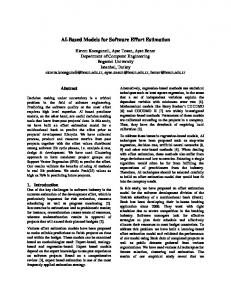
5.4 Figure 2: Modeling Environment for WF-CML Table 3: Development Effort Modeling/ Cognitive YAWL WF WF-CML Scaffolding YAWL WF WF-CML
SOM Top Level/Total 21/21 77/77 7/54 NALOC 857 1265 0
CFC
CW
COMR
9 20 2 NAV 34 77 0
61 22 3 NAM 3 1 0
14/17 13/64 7/4 NAC 38 58 0
Models for the scenario using the three DSMLs, WF-CML, YAWL, and WF were created during the study. Due to the space limitation we are only able to show the screen shot for the WF-CML model, shown in Figure 2. The screen shots of the other models can be seen on the project’s web page2 . Both YAWL and WF require the exact sequence of 2
http://www.cis.fiu.edu/cml/
Discussion
The result of our experiments provides evidence on potential productivity gains of WF-CML with less development effort. However, there is a trade off between ease-of-use and runtime system resource utilization, as demonstrated by more memory and CPU usage of WF-CML compared to WF. YAWL has the most resource utilization due to its heavy weight workflow engine that supports full-blown workflow solutions. Since our work is just an initial attempt towards quantitative measurement of effort in using DSMLs during application development. There needs to be more empirical studies to validate the metrics presented in the paper. Also there are several limitations with our study as described below: (1) Only three DSMLs are investigated in this study. There needs to be a more comprehensive review of different categories of DSMLs to consolidate the classification of effort presented in the paper. (2) Metrics like CFC only measure a class of DSMLs that have explicit flow structures, such as process modeling languages (e.g., BPEL [12]) and the Call Processing language[17]. For declarative DSMLs, CFC would not be appropriate to measure the structural complexity. (3) The measurement of the cognitive effort in using DSMLs lack empirical evidence. More empirical eval-
uation is required to determine the impact of the cognitive effort in creating DSML models. The long term vision of this research includes the estimation of a single effort value for each DSML by doing a weighted sum of each of the potential metrics. This effort value will be used for determining the cost/benefit ratio of the DSML.
6.
CONCLUSION
In this paper, we investigated the measurement of the effort to realize applications using DSMLs. We present a classification of the effort, and propose metrics for each perspective of the effort. Many of the metrics come from program and model complexity research. This multi-dimensional measurement approach provides a systematic and quantitative way of measuring the claimed benefits of DSMLs, which is addressed in a limited fashion in the literature. The validity of our metrics needs further validation.
7.
ACKNOWLEDGMENTS
This work was supported in part by the National Science Foundation under grant HRD-0833093, CCF-1018711, CCF0854988 and US Dept of Ed. grant P200A070543.
8.
REFERENCES
[1] P. Baker, S. Loh, and F. Weil. Model-driven engineering in a large industrial context - motorola case study. In MoDELS, pages 476–491, 2005. [2] D. Batory, B. Lofaso, and Y. Smaragdakis. Jts: Tools for implementing domain-specific languages. In In Proceedings Fifth International Conference on Software Reuse, pages 143–153. IEEE, June 1998. [3] J. Cardoso. How to measure the control-flow complexity of web processes and workflows. In The Workflow Handbook, pages 199–212, 2005. [4] M. Chaudron and C. F. Lange. Second international workshop on model size metrics. In Models in Software Engineering: Workshops and Symposia at MoDELS 2007, pages 89–92, Berlin, Heidelberg, 2008. Springer-Verlag. [5] M. Corporation. Windows workflow foundation, 2010. [6] Y. Deng, S. M. Sadjadi, P. J. Clarke, V. Hristidis, R. Rangaswami, and Y. Wang. Cvm - a communication virtual machine. JSS, 81(10):1640–1662, 2008. [7] D. Forum. Domain specific modeling, 2010. [8] G. C. Gannod and B. H. C. Cheng. A framework for classifying and comparing software reverse engineering and design recovery techniques, 1999. [9] T. R. G. Green and M. Petre. Usability analysis of visual programming environments: a ‘cognitive dimensions’ framework. JOURNAL OF VISUAL LANGUAGES AND COMPUTING, 7:131–174, 1996. [10] Z. Hemel, R. Verhaaf, and E. Visser. Webworkflow: An object-oriented workflow modeling language for web applications. In MODELS ’08, pages 113–127, Berlin, Heidelberg, 2008. Springer-Verlag. [11] F. Hermans, M. Pinzger, and A. Deursen. Domain-specific languages in practice: A user study on the success factors. In MODELS ’09, pages 423–437, Berlin, Heidelberg, 2009. Springer-Verlag.
[12] IBM. BPEL4WS, Business Process Execution Language for Web Services Version 1.1, 2003. [13] D. Kafura. A survey of software metrics. In ACM ’85: Proceedings of the 1985 ACM annual conference on The range of computing : mid-80’s perspective, pages 502–506, New York, NY, USA, 1985. ACM. [14] J. Karna, S. Kelly, and J. pekka Tolvanen. Evaluating the use of domain-specific modeling in practice. In Proceedings of DSM09, 2009. [15] R. B. Kieburtz, L. McKinney, J. M. Bell, J. Hook, A. Kotov, J. Lewis, D. P. Oliva, T. Sheard, I. Smith, and L. Walton. A software engineering experiment in software component generation. In ICSE ’96: Proceedings of the 18th international conference on Software engineering, pages 542–552, Washington, DC, USA, 1996. IEEE Computer Society. [16] A. Leff and J. T. Rayfield. Webrb: evaluating a visual domain-specific language for building relational web-applications. SIGPLAN Not., 42(10):281–300, 2007. [17] C. U. Network Working Group. Call Processing Language (CPL), 2004. [18] Object Management Group. Unified modeling language: Superstructure, version 2, February 2009. [19] L. Safa. The making of user-interface designer a proprietary dsm tool, 2007. [20] J. Shao and Y. Wang. A new measure of software complexity based on cognitive weights. IEEE Canadian Journal of Electrical and Computer Engineering, 83:69–74, 2003. [21] V. Sugumaran and V. C. Storey. The role of domain ontologies in database design: An ontology management and conceptual modeling environment. ACM Trans. Database Syst., 31(3):1064–1094, 2006. [22] W. van der Aalst and A. H. M. T. Hofstede. Yawl: Yet another workflow language. Information Systems, 30:245–275, 2003. [23] WF-CML Development Team. Workflow communication modeling language, 2010. [24] J. White. Simplifying autonomic enterprise java bean applications via model-driven development: a case study. In SoSyM, pages 601–615, 2005. [25] C. Wienands and M. Golm. Anatomy of a visual domain-specific language project in an industrial context. In MODELS ’09, pages 453–467, Berlin, Heidelberg, 2009. Springer-Verlag.