Mesh Generation Geometry Algorithm Based on Macro-Element Decomposition M.P.Levin
Abstract. An analysis of a geometry mesh generation algorithm based on macro-element decomposition by a modified front method is provided. This algorithm is intended for generation of finite element unstructured meshes for complicated 2D multi-connected regions. Some numerical examples shown the efficiency of considering algorithm are presented.
1. Introduction In recent years various types of algorithms intended for grid generation of finite element and finite difference unstructured grids are proposed and considered [1-2]. Among these algorithms, the geometry algorithms [3-5] play very important role, because usually they are very fast in comparison with other techniques based on analytical methods and very often could generate unstructured grids with sufficient quality. Various types of the front method [4-5], Delaunay and Voronoi triangulation methods are mostly popular among the geometric algorithms in recent years. In comparison with Delaunay and Voronoi methods, the front algorithm and its modifications are more simple and fast. In further computations, grids obtained by geometry methods can be improved by multigrid [6] or some other fitting technique proposed in recent years [7]. In this paper we consider one geometry technique of unstructured grid generation based on a macro-element decomposition of initial 2D multi-connected regions containing holes, cuts and isolated fixed points. In this technique at the first stage, the data region is decomposed into quadrangle or triangle macro-elements by modified front method and after that these macro-elements are partitioned into compatible set of quadrangle or triangle grid elements. To provide a quality of grid cells in finite element sense, the process of macro-element partition by the front technique is controlled by some quality criterions. Users could controlled the process of grid generation by setting some parameters defined this process and features 2000 Mathematical Subject Classification: 65M50, 65M55, 65M60, 65N50. Key words and phrases: mesh generation and refinement, domain decomposition, front method, unstructured meshes.
2
M.P.Levin
of the initial region. At the second stage, all macro-quadrangles and triangles are divided into compatible set of quadrangle and triangle sells according to the data mesh step. Various numerical examples show that considering technique could be efficiently used for fast generation of unstructured grids with high quality.
2. Partition of multi-connected regions by macro-elements Let us consider a problem of multi-connected 2D region partition into the set of quadrangle or triangle macro-elements. For simplicity, we suppose that external or internal boundaries of the initial regions are polygons and fixed isolated points also are considered as an internal boundaries. Also for simplicity, we suppose that polygon sides are straight segments, but without any difficulties our consideration could be expanded to the case when the polygon sides are circle or ellipse arc segments. In last case in the considering algorithm, we only need to take into account instead of curvilinear segments their spans. The basic idea of the front algorithm consists in boundary compression of the data region boundary. But in multi-connected case there are two type boundaries, namely external and internal boundaries. Therefore at the first step, we transform the data multi-connected region into the single-connected region with only one external boundary. For this purpose we define cut lines connecting internal and external boundaries. This definition we provide by the following manner. Let us find the nodal point of any internal contour lying on the minimal distance with respect to the external contour. Then at the second step, we connect the external contour and the appropriate nodal point of the chosen internal contour by the cut line corresponding to the minimal distance. In result, we obtain a new external contour instead of the previous external and chosen internal contours. Further following step by step procedure, we create a single-connected description of the boundary for the data region. Here we could mention about some features of the above mentioned procedure. In applications sometimes we need to generate meshes with ribs parallel to any data directions (we call these direction main directions). In this case it is convenient to evaluate the minimal distance with respect to the main directions and to define the appropriate cut lines parallel to one of the main directions also. After creation of data region description as the single connected domain, we consider a realization of boundary compression method. • At the FIRST STEP we choose any apex of the boundary as a start point of bypass and denote it as A. • At the SECOND STEP we define a direction of bypass. • At the THIRD STEP let us define a set of three (or two, if it is not possible to take into consideration three apexes) current apexes below the point A in the direction of bypass. We denote these apexes B, C, D accordingly. • At the FOURTH STEP we provide an analysis of the quadrangle ABCD (or triangle ABC) according to the following criterions:
Mesh Generation Geometry Algorithm
3
– A. Does this quadrangle (triangle) fully belong to the considering region? – B. Is quality of this quadrangle (triangle) good? (This problem will be discussed later.) – C. Does any self cross-sections not exist in it? • If criterions 1-3 are satisfied, then we take quadrangle ABCD (or triangle ABC) as a new macro-element, place it into macro-element list and create a new description of the considering region excluded this element. After that we go to the THIRD STEP of our algorithm. Otherwise we go to the FIFTH STEP. • At the FIFTH STEP we take point B as the start point of the bypass instead of point A and return to the THIRD STEP. The above mentioned process is repeated until we could generate new macroelements during the current bypass of the boundary or until the boundary become exhausted. In last case the partition process is finished and in the first case to continue the partition we need to relax restrictions in the quality criterion for the selection of macro-elements. Relaxing these restrictions, if it is necessary we could successfully finish the partition procedure. Thus the description of the principal ideas of macro-element partition algorithm is finished. Further let us consider some its features and more properly realization of above mentioned quality criterions. 2.1. Quality conditions Here we discuss a quality conditions for the criterion B. It is well-known that a norm of the finite element approximation error depends on the form of the finite elements. As well known theoretical estimations [X-Y] shown its minimum is achieved for the equilateral triangles or for the square elements. Since the optimal value of angles for quadrangle macro-elements is αopt = π2 and for triangle macroelements is αopt = π3 . Then we can formulate the following the quality criterion for the selection of new macro-elements in the partition process: maxi=1,2,...,N |αi − αopt | < (1 − ²). maxi=1,2,...,N |αi | Here N is a number of angles of macro-elements (N = 3 for triangles and N = 4) and ² is a data exactness for comparison. The value of ² is changed in the partition process by the following manner. If after the current bypass we could not generate a new macro-element, then we increase the value of ² and start a new bypass. There are possible various strategies for increasing of ². In our algorithm we increase its value from 0.8 till 0.0 by step 0.2. 2.2. Using of main directions If the main directions are set, then we usually wish to generate new macro-elements with new ribs (that are not a boundary ribs of the data external boundary of the considering region) parallel to the main directions.
4
M.P.Levin
For this purpose we modify the quadrangle procedure generation on the FOURTH STEP of our algorithm by the following manner. If criterions 1-3 are satisfied, then we define two lines passing through the point A and parallel to the main directions. Among these lines we choose one having a minimal angle with respect to direction BC. Let us define its intersection with the line CD as point d. Also we define two lines passing through the point D and parallel to the main directions. Among these lines we choose one having an minimal angle with respect to direction BC. We define its intersection with the line AB as point a. Now we analyze the following condition: Does point a belong to the segment [AB]? In TRUE case we take a quadrangle aBCD as a new macro-element instead of quadrangle ABCD in previous version of our algorithm, place it into macro-element list, create a new description of the considering region excluded this element and go to the THIRD STEP. Otherwise we analyze the another condition: Does point d belong to the segment [CD]? In YES case we take a quadrangle ABCd as a new macro-element instead of quadrangle ABCD, place it into macro-element list, create a new description of the considering region excluded this element and go to the THIRD STEP. Otherwise we go to the FIFTH STEP.
2.3. Junction of macro-elements The considered above technique allows us to provide the partition of the data region into quadrangle and triangle macro-elements. Very often, as our experience shown, we can generate a final unstructured triangle and quadrangle mesh with better quality, if before the partition of macro-elements we make a junction of these elements and create more rough macro-element partition, of course, if it is possible. This junction can be provided by the following algorithm. • Step 1. We choose any macro-element as a pivoting element. • Step 2. We take one of its neighborhood macro-element. • Step 3. If junction of these macro-elements produces a new quadrangle or triangle macro-element, then we analyze the quality of this new element according to criterions formulated in subsection 2.1. • Step 4. If quality of the new macro-element satisfies to the above mentioned conditions, then we take it as a new macro-element, create a new macro-element description of the data region and go to Step 3. • Step 5. Let us take another neighborhood macro-element, if it exist. • Step 6. If there is not any new neighborhood element, then choose a new pivoting macro-element and go to Step 2. • Step 7. If we could not choose a new pivoting macro-element, then the partition process is over.
Mesh Generation Geometry Algorithm
5
3. Partition of macro-elements In this section we consider a problem how to provide compatible partition of macro-elements. This problem can be solved by the following manner. At first we consider the partition including only quadrangle macro-elements. In this case we could create a data base of all macro-element ribs.
• STEP 1. In this data base of macro-element ribs we choose any not partitioned yet rib as a pivoting rib and make partition of it with a data spatial step. • STEP 2. In all quadrangle macro-elements including this rib, we find all opposite ribs to the pivoting rib and make partition of these ribs with the same number of segments as in the pivoting rib. • STEP 3. Let us take the set of new divided ribs as pivoting ribs and find all opposite and not yet partitioned ribs. • STEP 4. If we find any new not yet divided opposite ribs, then we divide these ribs and continue the process. Otherwise we find any other not yet partitioned rib as pivoting rib and go tho the STEP 2.
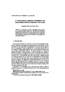
Following to above mentioned algorithm we can provide the full compatible partition of all regions divided by quadrangle macro-elements. Now we consider a more complicated case, when the partition contains some triangle macro-elements. In reality, this problem is more simple than the previous, because triangle macro-elements allow us to make compatible partition into triangles even in case than sides of any considering triangle are divided by the different number of segments. This facility is shown in Fig.1a and in Fig.1b. We construct partition of this triangle macro-element by straight segments connecting the center of triangle (the point of triangle medians intersection) and the nodes on triangle sides. In result we obtain a set of triangles and to provide a more fine compatible partition of generated triangles, we divide the segments connecting the center of
6
M.P.Levin
Fig.1a. Macro-element partition of triangle.
Fig.1b. Meshing of triangle.
Fig.1c. Improved meshing of triangle. macro-element and nodes on ribs, by the same set of lines parallel to macroelement ribs as shown in Fig.1b. In result, we obtain the set of quadrangle and triangle cells. After that analyzing this set, we can joint some neighborhood sells to improve the quality of generated cells in the center of the macro-element triangle as shown in Fig.1c. Therefore, the triangle macro-elements always are able to resolve collisions sometimes arisen in very complicated cases of quadrangle macro-element
Mesh Generation Geometry Algorithm
7
partitions. Thus, if we obtain any quadrangle macro-element with opposite sides partitioned by the different number of nodes, then we can avoid difficulties in grid generation of this macro-element by dividing it into two triangles and further partition of these triangles by triangle cells.
4. Numerical examples In this section, let us consider some numerical examples of the unstructured grid generation obtained by the technique considered in previous sections. In the first example the data domain is described by straight line segments. Fig.2a shows this complicated 2D multi-connected domain containing isolated fixed point shown by a small square and internal contours. Its partition into macroelements is shown in Fig.2b. The unstructured grid for this domain is shown in Fig.2c. We can see that this grid consists only of quadrangle cells.
Fig.2a. Data region.
Fig.2b. Macro-element partition.
8
M.P.Levin
Fig.2c. Unstructured grid. In the second example the data domain is described by straight line, circle and ellipsoid segments. Fig.3a shows this multi-connected domain containing internal curvilinear contour. The partition of this domain into macro-elements is shown in Fig.3b. Fig.3c shows the appropriate unstructured grid for this domain. It also consists only of quadrangle cells.
Fig.3a. Data region.
Mesh Generation Geometry Algorithm
9
Fig.3b. Macro-element partition.
Fig.3c. Unstructured grid.
5. Conclusions The grid generation geometry algorithm considered above is very fast and allows generate unstructured 2D finite-element grids for very complicated domains without any problems. It also should be mention that introducing some fictive fixed points, contours and cut lines in description of the data region, users can take into account peculiarities of considering domain and construct more fine grids. Also the macro-element partition described above can be used as a decomposition of the considering region together with the substructuring technique for the acceleration
10
M.P.Levin
of numerical solution of huge systems of linear algebra equations arising in finite element approximations of elliptic boundary-value problems [8].
References [1] P.L.George, Automatic mesh generation: application to finite element methods, New York, Wiley, 1991. [2] Handbook of grid generation, ed. J.F.Thompson, K.Bharat and N.P.Weatherill, Boca Raton, CRC Press, 1999. [3] C.M.Hoffmann, Geometric approaches to mest generation, in: Modeling, Mesh Generation, and Adaptive Numerical Methods for Partial Differential Equations, ed. I.Babuska, W.D.Henshaw, J.E.Oliger, J.E.Flaherty, J.E.Hopcroft, T. Tezduyar, New York, Springer-Verlag, 1995, pp. 31–51. [4] S.H.Lo, Unstructured grid generation/advanced front methods, International Journal for Numerical Methods in Engineering, 21 (1985), pp. 1403–1426. [5] J.Peraire, M.Vadhati, K.Morgan and O.C.Zienkiewicz, Adaptive remeshing for compressible flow computations, Journal of Computational Physics, 72 (1987), pp. 449– 466. [6] P.Wesseling, An introduction to multigrid methods, Willey, New York, 1992. [7] R.Becker and M.Braack, Multigrid technique for elements on locally refined mashes, Numerical Linear Algebra with Applications, 7 (2000), pp. 363–379. [8] M.P.Levin, Substructuring technique and parallel computations, Trends in Mathematics, 4 (2001), pp. 108–115.
Department of Aerospace Engineering, Korea Advanced Institute of Science and Technology E-mail address:
[email protected]; Mikhail
[email protected]