Method Fragments for agent design methodologies: from standardization to research M. Cossentino Istituto di Calcolo e Reti ad alte prestazioni, (ICAR) - Consiglio Nazionale delle Ricerche (CNR), Palermo,Italy SET - Universit`e de Technologie Belfort-Montb`eliard - Belfort, France E-mail:
[email protected]
S. Gaglio DINFO - Universit`a degli studi di Palermo - Palermo, Italy Istituto di Calcolo e Reti ad alte prestazioni, (ICAR) - Consiglio Nazionale delle Ricerche (CNR) - Palermo, Italy E-mail:
[email protected]
A. Garro D.E.I.S. - Universit`a della Calabria - Rende, Italy E-mail:
[email protected]
V. Seidita DINFO - Universit`a degli Studi di Palermo - Palermo, Italy E-mail:
[email protected] Abstract: The method engineering paradigm enables designers to reuse portions of design processes (called method fragments or chunks in literature) to build processes that are expressly tailored for realizing a system that is specific for some problem or development context. This paper initially reports the standardization attempt carried out by the FIPA Methodology Technical Committee (TC) and then presents the research activities we did starting from that proposal; these resulted in a little different definition of some of the most important elements of the approach in order to support a multi-view representation of the fragment (the views are process, reuse, storing, and implementation). The paper also describes the documents we use for representing a fragment and concludes with an example. Keywords: Software Engineering Process, Methodologies, Multiagent systems.
1
Introduction
• the agent-oriented philosophy for modelling and managing organizational relationships is appropriate for dealing with existing dependencies and interactions (Jennings, 2001).
In the last years, the agent-oriented approach (Bauer et al., 2001; Jennings, 2001) has been recognized as very suitable for the development of complex software systems since it fully exploits the well known techniques of Decomposition, Abstraction and Organization (Booch, 1994) for helping to manage complexity. In particular in the context of complex software systems:
The development of complex software systems by using the agent-oriented approach requires suitable agent-oriented modelling techniques and methodologies which provide explicit support for the key abstractions of the agent paradigm. Several methodologies supporting analysis, design and • the agent-oriented decomposition is an effective way implementation of Multi-Agent Systems (MASs) have been of partitioning the problem space; to date proposed in the context of Agent Oriented Software • the key abstractions of the agent-oriented mindset Engineering (AOSE) (Lind, 2001). Some of the emerg(agents, interactions, and organizations) are a natu- ing methodologies are Adelfe (Bernon et al., 2002), Gaia ral means of modelling; c 200x Inderscience Enterprises Ltd. Copyright ° 1
methodology (by retrieving the method fragments (Zambonelli et al., 2003), MaSE (DeLoach, 2001), Message from the method base and integrating them) and ap(Caire et al., 2002), Passi (Cossentino, 2005), Prometheus ply it in the real design work. (Padgham and Winikoff, 2003), and Tropos (Bresciani et al., 2004) . Although such methodologies have different adA more ambitious goal was enabling the use of: vantages when applied to specific problems, it’s a matter of fact that an unique methodology cannot be general enough • CAP E (Computer Aided Process Engineering) tools to be useful to everyone without some level of customizathat could enable the construction of the new design tion. In fact, agent designers, for solving specific problems process; these tools should be able to support the defin a specific application context, often prefer to define their inition of the process life-cycle as well as the reuse of own methodology specifically tailored for their needs infragments from the method base. They should enable stead of reusing an existing one. Thus an approach that the adoption of a specific process life-cycle (waterfall, combines the designer’s need of defining his own methodoliterative/incremental, spiral, . . . ) and the placing ogy with the advantages and the experiences coming from of different fragments in it. The CAPE tool should the existing and documented methodologies is highly re“instantiate” a proper CASE tool (see below) that quired. is specifically customized to support the designer in A possible solution to this problem is to adopt the working with the composed methodology. method engineering paradigm so enabling designers of • CAM E (Computer Aided Method Engineering) tools MAS to (re-)use parts coming from different methodologies that could offer specific support for the composiin order to build up a customized approach for their own tion/mainteinance of a method fragment; these tools problems (Henderson-Sellers, 2003). According to this apshould enable the definition of a method fragment proach, the “development methodology” is constructed by accordig to its definition and the prescriptions comassembling pieces of other methodologies (method fraging from the method base; besides they would allow ments) from a repository of methods (method base). the modification of these fragments when assembling The method base is built up by taking method fragments needs or other customization requests could emerge. coming from existing methodologies or ad hoc defined methods. This approach has been adopted, in the past • CASE (Computer Aided Software Engineering) tools few years, by the FIPA Methodology Technical Committee that assist the designer in performing the development (TC) (Foundation for Intelligent Physical Agents (FIPA)) process based on the composed methodology. These in which the authors were active members. FIPA recently tools should be the evolution of existing CASE instrumoved to the IEEE Computer Society under the name of ments since they enforce the execution of the design IEEE FIPA Standards Committee and in this occasion the phases in the the order defined at the methodology activity of the Methodology TC stopped. composition time (accordingly to the adopted process The FIPA Methodology Technical Committee (TC) has life-cycle Cernuzzi et al. (2005)) and they guide the been constituted in 2003 with the aim of capitalizing the designer in profitably applying it. efforts of many researchers in the area of MASs design and contributing to the reuse of parts of existing mehtodologies The work done by the FIPA Methodology TC can be (and the related knowledge) through an appropriate set of summarized as follows: definition of a method fragment specifications meta-model (including an XML-based method fragment More in details, the main goals of the TC were: representation); definition of a method base general architecture; representation of some methodologies using a pro• Definition of the method fragments meta- cess description language, the TC adopted OMG SPEM model. It is necessary to formally represent method (Software Process Engineering Metamodel) (SPEM, 2002), fragments in order to facilitate their identification, the described methodologies are: ADELFE, Gaia, and representation, integration and storing in the method PASSI (see the TC documents (Gleizes et al., 2003; Garro base; et al., 2004; Cossentino et al., 2004)); collection of method fragments, this has been done by extracting method frag• Identification of the method base architecture. ments from the previously listed methodologies according The method base needs of a technological infrastructo the defined method fragment meta-model (see the TC ture for the instantiation of the previously defined documents (Gleizes et al., 2004; Garro and Turci, 2004; method meta-model; Cossentino, 2004)), a new fragment that is specific to na and • Collection of method fragments. They can origin deal with complex systems has been listed too (Pe˜ Corchuelo, 2004); and finally, identification of some apfrom the most diffused methodologies and other speproaches and guidelines for methods integration. cific contributions. After the formalization they can This represent the first part of the work presented in be introduced in the method base; this paper, from the activity of the Methodology TC, we • Description of techniques for methods integra- started our own researches aimed at applying the protion. It is necessary to define guidelines for meth- posed specifications and eventually improving them. In ods integration in order to both construct the new the second part of the paper (sections 4, 5) we present
2
the results of these studies. We made minor changes to the structure of the fragment and we introduced new elements in it (the explicit support for the workflow of design activities, and other elements aimed at a successful implementation of the method fragment). In order to really experiment these definitions, we extended our interest to the study of the whole development process with a multiperspective approach that resulted in the representation of the fragments according to the following views: process, reuse, storing, implementation. We furtherer improved the FIPA repository with new methodologies/fragments, we produced a web-based method base and finally we realized some experiments also with the support of some prototypical CAME/CASE tools. In the next sections these points will be discussed in details.
2
Henderson-Sellers, 2002, 2005, 2006; Ralyt´e and Rolland, 2001; Rolland and Prakash, 1996; Hofstede and Verhoef, 1997; Tolvanen et al., 1996), all of them start from the same consideration that the growing complexity of systems needs ad hoc methodologies and that the three previously cited elements are the core points but each of them provide different meanings and definitions basing on the specific domain they are working on and the specific development context; that is even if they all share the same main phases for a method engineering process: method requirements definition, method fragments selection and method fragments assembly. The (situational) method engineering paradigm, which until now we illustrated referring to the information system context, can be obviously used and extended to all the cases in which a complex system has to be developed using a purposefully created methodology and in particular we are working on adapting this approach to the development of multi-agent systems design methodologies. Before introducing the work done within FIPA on the matter, we would like to adopt an unique denomination for the process composed by applying the method engineering paradigm (but also for the process from which the method fragments were extracted). In literature we can find authors using the terms methodology (the preferred one in the agent context), process, design process and also software design process. In order to avoid confusion and not to participate to this debate, we will adopt a wide enough definition coming from Fuggetta (Fuggetta, 2000) who defined a Software Engineering Process (SEP hence after) as “the coherent set of policies, organizational structures, technologies, procedures, and artifacts that are needed to conceive, develop, deploy, and maintain (evolve) a software product”. The approach proposed by the FIPA Methodology TC is an extension of the method engineering paradigm as proposed in (Brinkkemper, 1996; Kumar and Welke, 1992; Saeki, 1994). As already said, according to this approach, a SEP is built up by assembling pieces of the process (method fragments) (Brinkkemper et al., 1996, 1999; Ralyt´e and Rolland, 2001) taken from a repository of methods that has been built by extracting pieces from existing design processes. Besides (and this has been decisive in the FIPA context), this approach allows the contribution of a large community (several design processes for MAS design already exist in literature (Luck et al., 2004)) without imposing any kind of discrimination on what is “compliant” and what is not. Compliant SEPs would be simply composed by reusing parts from the repository accordingly to the proposed guidelines, nothing more than that. Most of all, different contributions to the repository are valuable because they are the consequence of some specific need, development context, application environment or theoretical background and as such they can be profitably reused when something similar is found in facing a new problem (just like a bridge pattern (Gamma, 1994) can be reused whenever it is necessary to decouple an interface from an implementation, regardless of the original context that al-
Method Engineering
The term Method Engineering was coined by Kumar and Welke in 1992 (Kumar and Welke, 1992) when they realized that a standard design methodology suitable for each kind of problem did not exist so they proposed the engineering of new methodologies starting from the composition of techniques in order to meet a specific problem in a specific application context. Successively Brinkkemper defined the method engineering as “the engineering discipline to design, construct and adapt methods, techniques and tools for the development of information systems” (Brinkkemper, 1996). All of them worked in the field of information systems where the growing complexity of systems led designers to modify and adapt the design methodology in order to meet the needs arising from the particular problem/context they were working on and the specific skills they had; as a consequence of this trend, the term Situational Method Engineering grew up (Harmsen and Brinkkemper, 1995). Situational Method Engineering is mainly based on the concept of reuse and on the belief that each methodology can be decomposed in parts (components) so that a designer can create an ad hoc methodology by starting from these reusable parts (called method fragments); hence the method fragment is the most important element when applying the method engineering paradigm. Method fragments have to be extracted from existing design methodologies and stored in a repository, called method base, from which they are retrieved during the process of new method construction by the designer (the method engineer); obviously the definition of a proper assembly technique is of fundamental importance for the successful application of this approach. Thus it is a matter of fact that three elements have to be considered during a method engineering process: the method fragment, the repository and the assembly techniques. Different approaches today exist for the application of the method engineering paradigm (Brinkkemper, 1996;
3
lowed the identification of this pattern). 2.1
al., 2003) for further details), by now it’s worth noting that designing an agent society is characterized by fundamental choices about the social structure (peeragents, hierarchical organizations and so on) or the agent architecture (reactive, BDI, state-based, . . . ) that becomes a kind of requirement for the SEP. They often descend from the development context or the specific problem to be solved: a company that has a consolidated tradition in adopting BDI agents organized in groups of peer agents will more likely choose a similar form of society for solving future problems rather than change it if not really necessary (or remarkably profitable); as a consequence, the new SEP should encompass these choices.
Method Engineering and Agents
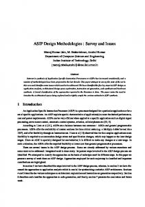
Some authors already started to work in this direction in the agent community (Cossentino and Seidita, 2004; Garro and Palopoli, 2003; Henderson-Sellers, 2005; Juan et al., 2002) thus confirming that the method engineering paradigm can be profitably applied to multi-agent systems design too. Figure 1 describes the approach to the whole method engineering process studied by the FIPA Methodology TC. Although this was not intended to be a standardization issue, its definition was supposed to help members in practicing the construction of new SEPs. It includes three main phases: the fragments repository construction, the SEP definition and the SEP enactment. The fragments repository is built by conveniently modularizing the existing design processes and converting them to the method fragment structure defined by the TC (see section 3). The identification of guidelines for fragments extractions from existing processes has not been studied during the FIPA Methodology TC activity although it has some effect on the fragment structure (for instance on its granularity). This problem is still an open research issue and some contributions can be found in (Ralyt´e and Rolland, 2001; Brinkkemper et al., 1999; Cossentino and Seidita, 2004). The method base can also list fragments not coming from an entire process but conceived as stand alone contributions to the repository. This is the case of the MaCMAS fragment that allows dealing with the analysis phase of complex systems (Pe˜ na and Corchuelo, 2004). The TC members regarded this is a relevant contribution to the research on AOSE: it proved that it is no more necessary to prepare an entire design process in order to study one single aspect of agency. A researcher can focus his own attention on the specific problem he wants to study and then complement the resulting method fragment(s) with others coming from the method base thus quickly completing a process that he can use to test the results of his work. During the SEP construction, the method engineer, has to consider several different factors that effect his work:
• Agent is not a well defined concept; several different definitions can be found in literature (Russell and Norvig, 1995; OMG Agent Platform, 2000; Franklin and Graesser, 1996) and this also includes most of the concepts used when defining a MAS (role, task, behavior, goal, . . . ). The MAS is usually designed and implemented by considering abstractions and components that could be significantly different. Several studies have been carried out during these last years about MAS meta-models (Odell et al., 2005; Bernon et al., 2004; Caire et al., 2002; Ferber and Gutknecht, 1998; Bernon et al., 2005) and a final result has not been achieved. The same absence of a real, pure agentoriented coding language is the consequence of this situation (most diffused solutions are Java-based). The FIPA Methodology TC approach encouraged studies in this direction and allowed an easier application of their results since the method fragment definition given by this TC explicitly considers the MAS metamodel elements involved in its workflow and artefacts. The construction of a new SEP is a well-studied phase within the method engineering community and nonetheless it is still open to new contributions. During the Methodology TC activity no specific work has been done on that; members of the committee applied the techniques they considered more productive. Generally speaking we can say that usually in order to compose a new process, the activities to be done are: selection of fragments from the method base, assembling of fragments, adaptation of fragments that do not perfectly fit the new process in their native structure. This activities will be further described in the following sub-section. The resulting SEP will be essentially composed of a flow of activities to be done, the descriptions of a set of artefacts, the related guidelines and the suggested notation for the required artefacts. During the last phase (SEP enactment), the system designer, adopts the new process (and the supporting CASE tool) to design a MAS-based solution to the problem he is facing and in so doing, he produces the required artefacts accordingly to the process guidelines. In the following section the method fragment definition will be introduced.
• The SEP should be fitted for the specific family of problems it will be applied. This means that if the problem is typically effected by some constraint (e.g. real-time or security issues) it should include proper methods to explicitly deal with them. • The SEP is to be used by persons. This means that the method engineering should compose a SEP that is coherent with their skills (or at least not too far); a group of designer already skilled with some design practice should not be forced to change this use if it is possible to adopt (eventually part of) the old approach to solve the new problem. • Designing agents is different from designing objects. Several papers deal with this issue (this is out of the scope of this paper, see (Odell, 2002; Zambonelli et
4
4. A list of components of the MAS meta-model to be defined or refined through the specified process (they belong to the MAS meta-model adopted by the methodology from which the fragment was extracted); while this list could be theoretically speaking void (this is for instance the case of a fragment whose purpose consists in selecting between two different paths in the design process accordingly to the evaluation of some aspects of the actual design), all the fragments that have been up to now identified, are concerned with some components to be defined/refined, thus showing that the community is, by now, still more concerned about a product-oriented identification of fragments rather than a process-oriented one.
Figure 1: The discussed Agent-Oriented Method Engineering process 3
5. Application guidelines that illustrate how to apply the fragment and the related best practices; the same formalization of these guidelines in the existing agentoriented methodologies has its own specific importance since otherwise, except for a few well documented approaches, guidelines often remain bounded to the personal knowledge of some skilled designers or the methodology creators.
A Proposal of Fragment from the FIPA TC
The FIPA methodology TC started his work by giving a definition of the method fragment and complementing it with some studies on MAS meta-models and a glossary of terms. As regards the method fragment (Method Fragment Definition, 2003), it is considered as a portion of the development process, composed of the following parts:
6. A glossary of terms used in the fragment; this avoids misunderstandings if the fragment is reused in a context that is different from the original one; in order to facilitate this part of the fragment documentation the members of the TC discussed a list of definitions for many commonly used terms.1
1. A specification of the portion of process which defines what is to be done by the involved stakeholder(s) and in what order. The fragment specification prescribes the use of the OMG SPEM (SPEM, 2002) for describing its procedural aspect. According to SPEM, the FIPA fragment can be regarded as a process component.
7. Composition guidelines which describe the context/problem addressed by the specific fragment and that is behind the methodology from which it has been extracted.
2. One or more deliverables such as AUML/UML diagrams (Bauer et al., 2001) and text documents; these should be part of the fragment specification in form of a description of their structure (in order to clarify what is the expected output of the presented activities) also including a reference to the suggested (or adopted, in the original methodology from which this fragment has been extracted) modelling notation.
8. Aspects of fragment; they are textual descriptions of specific issues such as platform to be used for system implementation, application area, etc; this helps in delimiting the proper application field for the fragment. 9. Dependency relationships useful to assemble fragments. When the fragments granularity is fine grained (and the FIPA repository is conceived to allow the introduction of different sized fragments) it is frequent to reuse more fragments from a specific methodology since their adoption probably corresponds to adopting some philosophy for the composition of a specific portion of the SEP.
3. Some preconditions which represent a kind of constraint specifying when it is possible to fire the activities specified in the fragment. They are usually related to the required input data; these preconditions can be thought as the similar preconditions in a contract between two classes. In particular, the preceding fragment (or the n preceding fragments) is/are responsible for establishing the conditions that will enable the successful execution of the following fragment. The formalization of this preconditions would allow the introduction of some kind of automatic assistance in the composition of the fragments but a formal language has not been specified nor adopted yet and the only considerations that can be easily automated according to this specification, regards the required input set in terms of already defined MAS meta-model components (see below).
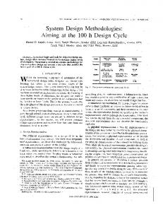
It should be noted that although a complete description of the fragment in all of the above listed fields is advisable if possible, not all of these elements are always mandatory; some of them (for instance deliverable notation or guidelines) could be not applicable or not necessary for some specific fragment. The resulting method fragment is represented by using an UML Class Diagram in Figure 2 at the level of refine1 http://www.pa.icar.cnr.it/cossentino/FIPAmeth/glossary.htm
5
Figure 2: The method fragment defined by the FIPA methodology TC ment reached during the work of the TC; our further works on it are presented in the following sections. According to the reported definition of method fragment the method base structure proposed by the FIPA Methodology TC is an XML based repository storing a collection of XML document, each one representing a method fragment, validated by a DTD or an XML Schema. In fact, the proposed method fragment meta-model can be easily translated in a XML Document Type Definition (DTD) or in a XML Schema that can be used for validating an XML document representing a particular method fragment. The validation process ensures that the method fragment was extracted and defined according to the prescribed metamodel. It is worth to point out that the XML document representing a fragment is not self-contained but could contain some URI addressing resources that can not be coded in XML but that are nonetheless part of the fragment. The repository is oriented toward a MAS meta-model based classification of fragments; each one of them is in fact labelled with the MAS meta-model components that are defined or refined during its activities. Each activity has some inputs and produces some outputs in terms of defined/refined components of the MAS meta-model. The instances of these components are reported in the fragment work products (text documents or diagrams with a link to the adopted notation) that are related to those activities. The fragment preconditions are represented in terms of required work products or guard conditions (these can for instance detail the required refinement level of some elements of the MAS meta-model). Further details about the repository implementation or querying approaches have been considered out of the scope of the work of the TC and left to tool implementers. The definition of the fragment meta-model was the main aim of the FIPA Methodology TC and it had been proposed to the FIPA board but the interruption of the activities and the subsequent moving of FIPA within the IEEE
Standards Society stopped the publication process of the work as a preliminary specification. In the following sub-section an important phase of the construction of the new SEP, the method fragment integration, will be discussed. 3.1
Method fragments integration
Method fragments integration is the process of composition of the new SEP and usually consists of two different and complementary phases: the selection of the reused fragments from the method base and their assembling (here including the modification of fragments when necessary). Several approaches exist in literature to deal with these crucial phases, among the others the work of Ralyt´e where fragments are composed by association and integration (Ralyt´e and Rolland, 2001b), and the Brinkkemper’s paper (Brinkkemper et al., 1999) where the composition process is based on three orthogonal dimensions: perspective, abstraction and granularity. The FIPA Methodology TC members discussed about this topic and, specifically, they mainly studied two basic approaches for the integration of methods during the construction of the agent-oriented SEP (Garro et al., 2004): (i) meta-model driven, which is based on the MAS metamodel adopted by the designer for the development of a MAS for a specific problem in a specific application domain; (ii) development process driven, which is based on the instantiation of a software development process in which each phase is carried out using appropriate method fragments selected on the basis of the supported activities and of the resulting work products. Both of the proposed approaches have been experimented by the authors in various applications and case studies. For instance, the meta-model driven approach to method fragments integration was exploited for the construction of a SEP suitable for developing a MAS for the
6
prediction of the three-dimensional structures of proteins (Garro et al., 2004a) and a MAS for E-Learning and Skill Management context (Garro and Palopoli, 2003). The development process driven approach to method fragments integration was exploited for the construction of a SEP for the modelling and the validation through simulation of MAS (Fortino et al., 2004). These two approaches will be further explored and then compared in the following sub-sections.
It’s worth noting that if two subsequent phases (P1 and P2 ) are carried out by using method fragments coming from different methodologies, it may be necessary to elaborate the work products of phase P1 to obtain the information needed to drive the construction of the work products of phase P2 . In other words, the work products produced in a given phase might constitute the input for the subsequent phase provided that they contain all the information required for initializing it.
3.1.1
3.1.3
The MAS meta-model driven approach for method fragments integration
As it is usual in software engineering, each of the proposed approaches has advantages and drawbacks; beginning from the first, the meta-model driven provides flexibility for the definition of many aspects of the MAS to be developed; this is probably the most suited one if social rules coming from a specific domain play a relevant role in the problem to be solved. Conversely, it is characterized by a difficulty of integration of different fragments due to the different semantics of the concepts they can represent in the metamodels subsumed by the methodologies from which they have been extracted; further more, the a-priori selection and/or definition of the meta-model to adopt for the specific problem and/or application domain is a difficult and at the same time crucial task. The development process driven approach is characterized by the following advantages: flexibility for the construction of a SEP by means of the instantiation of each stage of the selected process life-cycle. On the other hand, the disadvantages are the following: (i) low flexibility of the MAS meta-model since it results from the sum of elements defined by the selected method fragments; (ii) adaptation among the work products which is sometimes difficult to achieve; (iii) choice and definition of the process life-cycle to instantiate for the specific problem and/or application context; (iv) low level of help in selecting the fragments that descend from the process life-cycle choice (several degrees of freedom still exist and other guidance are needed to select the proper method fragments). Each one of above listed points represents an open problem and a challenge for the agent community (most of these issues are indeed not specific of agent-related researches); the first one to be explored consists in some peculiarities that are related to the agent paradigm, the most important probably being the role that the agent social organization plays in the composition of the new process. The proposed approaches to the integration of methods fragments (meta-model driven and development process driven) are not mutually exclusive; rather, hybrid approaches containing features of both of them might be defined as well. An example of process composition that mixed both of the proposed approaches has been used to create one of the first agile processes for MAS design, PASSI Agile (Chella et al., 2004); it started from the selection of the life-cycle of an agile process and then a MAS meta-model has been defined by conveniently reducing the conventional PASSI one. Different approaches can be con-
To build a SEP by exploiting the meta-model driven approach, the designer has to: • choose or define the MAS meta-model suitable for the specific problem and/or the specific application domain; • choose the method fragments that are able to produce the identified meta-model elements; the first criterion here is related to the complete coverage of the metamodel instantiation procedure; • defining a development process characterized by a method fragments execution order on the basis of the relationship existing among the meta-model elements produced by each fragment; in this phase a kind of dependency matrix among the artifacts produced by the fragments could help together with opportunity considerations (for instance, in an agile approach, test planning is done as soon as it is possible). Hence, the obtained SEP is able to completely ensure the MAS meta-model instantiation for the given problem in a specific application domain. 3.1.2
Comparison of the approaches
The development process driven approach for method fragments integration
The development process driven approach focuses on the instantiation of a software development process that completely covers the development of MAS and complies with some specific needs related to it (like the creation of an extensive documentation or the flexibility in managing new requirements). To build a SEP by exploiting the development process driven approach, the designer must: • choose or define a SEP life-cycle suitable for the specific problem and for the specific application domain; this means for instance the adoption of a waterfall life-cycle if the customer explicitly requires it (as it happens in some government contracts) or an iterative/incremental one to cope with evolving requirements and development risks management; • instantiate the development process by selecting, for each phase of the life-cycle, some suitable method fragments, chosen from the method base or even adhoc defined.
7
Figure 3: The proposed representation of the Software Engineering Process including the fragment element used to compose it sidered as well (for instance some based on the attributes problems; these two elements constitute a precise indicaof the resulting process (Juan et al., 2002)) and their use tion on the requirements of process. is not in contrast with the presented ways. A process is composed of activities, the single piece of work to be done in order to produce a specific output (an activity in fact may produce a work product); each activity is performed by a process role that is responsible 4 A Refinement of the Proposal for one or more work products that are structured by a Figure 3 shows the elements a process for an agent-based work product kind representing a specific category, for indevelopment is composed of, it explicates and includes all stance text document, code an so on. In the case of text or the concepts we took into account when we started the re- structured documents (including texts, diagrams and/or finement of the results obtained by the Methodology TC. other elements) the work product kind also specifies the At this stage of the work, we prefer to adopt an informal document template (outline in terms of sections and subrepresentation of our (meta-)models in order to achieve sections, position of figures, number of columns in tables, a better readability of images containing a large number and so on). of elements and most of all, to convey attention to the concepts and their relationships (explicitly named in the diagrams) like it would happen in an ontological representation of the interest domain. As we can see in Figure 3 (and as already proposed in (Cernuzzi et al., 2005) we consider the process as the set of steps to be performed in order to produce an output, the way of performing some activities and the resources and constraints this requires. As we already said it is now well recognized that a standard process does not exist so each process is specific for a particular development context, which relates to resources, peoples and competencies aspects, and for a problem type, in fact it can solve a specific problem or a family of related
A process can be supported by a design tool for helping the designer in editing a work product; since each work product adopts a specific notation, the design tool has to be aware of this notation also providing some consistency checks on the work products it produces, during the development of the process, and some semantic and syntactic checks. A process in the agent oriented context aims at designing a MAS model whose elements (MAS model elements) are represented in the work products; for instance enacting an activity of a development process a designer may specify an agent that encapsulates some specific functionalities or (at a different stage of the design process) the roles the agent has to play to reach its goals; all these
8
elements are represented in the work product produced by the specific activity. A MAS model obviously is an instance of a MAS Meta-model that gives a structural representation, in terms of elements and relationships, of the concepts belonging to the system under construction; a MAS Meta-model is composed of MAS model elements that are instance of MAS Meta-model elements, this latter elements can be either a relationship or an entity. A process can be decomposed in (method) fragments that are self contained pieces of the whole process with all the elements characterizing (composing) the process itself (activity, process role, etc.); each fragment instantiates/refines/relates one or more MAS meta model element(s) that are represented in the fragment output work product(s) in form of portions of the MAS model that will solve the problem under study; each method fragment produces one or more work product(s) (of the same kind, of different kinds or even structured by composing different elementary documents like diagrams, tables and text).We understand that defining our fragment as a method fragment (or even a chunk ) could generate some confusion because of the existence of previous definitions for these concepts. Probably the name process fragment would better address our actual point of view on the matter but we prefer to maintain the old denomination in order to indicate the continuity of our work with the activities reported in the previous sections. In the figure we also represent the process life cycle element; each process adopts the life-cycle that more properly fit the problem, this will order the activities according to a well defined structure in order to cope with some philosophy; for instance the iterative/incremental life cycle is well suited to solve all the problems were requirements are not stable. Therefore the life cycle is useful to order fragments when we are assembling them in a new process. We think that the fragment is such a complex and fundamental element of the method engineering approach that it should be explored from several different points of view in order to achieve the deepest comprehension of its implications during design time. More specifically we identified four different views: process, storing, reuse and implementation; these views will be described in the following subsections. 4.1
neering ones. In our approach this workflow is described using activity diagrams (mostly SPEM activity diagrams) that also report the produced work products (see section 5. As already reported, each work product belongs to a work product kind. In (Seidita et al., 2006) we identified two main sets of work product kinds: graphical and textual. Graphical work product kinds include behavioural (describing the dynamic behaviour of the system or one of its parts/views) and structural artefacts (describing the structure of the system or one of its parts/views). Textual work products include: (i) free text documents: here we mean documents not observing a specific grammar like it happens for XML documents; they could nonetheless be organized according to an outline specified in a template of the work product; (ii) structured documents: they observe a rigid grammar (like it happens for XML documents and programming language code), include structured text (for instance tables) or can be composed of a mixture of the previous described work product kinds (for instance an analysis document including diagrams and the related textual description belongs to this type). In Figure 4 we can see that an activity has work product as an input and produces other work products. It is interesting to note that we explicitly represent fragment preconditions (already introduced by the FIPA Methodology TC) as conditions on the MAS model elements represented in the fragment input work products. Finally, in this view we can also find the process roles employed in performing this fragment activities and the guidelines that can support their work. 4.2
The Fragment Reuse View
This view is concerned with the reuse features of the fragment and lists the elements that can be helpful in reusing the fragment in the composition of a new SEP. The elements of the fragment meta-model that belong to this view are: • MAS meta-model element: this defines the scope of the fragment,the elements that it will instantiate in the produced work products. • Aspect, Glossary, Composition Guideline, Fragment Dependency: they have the meaning defined by the FIPA Methodology TC as reported in section 3.
The Fragment Process View
4.3
The fragment process view is aimed at representing the process-related aspects of the fragment. It includes the elements reported in Figure 4. The most important ones probably are workflow, activities, and work products. The workflow that we now introduce in the fragment, structures the activities; for its definition we refer to the WfMC (Workflow Management Coalition, 2005) specifications (Management Coalition, 1999): “The automation of a business process, in whole or part, during which documents, information or tasks are passed from one participant to another for action, according to a set of procedural rules”, with the obvious assumption that we are not dealing with business processes but rather software engi-
The Fragment Storing View
This view regards the storage of the fragment in the method base and its retrieval. This view includes the following elements: • Phase: this is seen according to the SPEM definition as another specialization of the Work Definition mother class as it is for the already cited Activity element. It is regarded as a big composed work definition usually built up from several finer activities. Examples of phases can be: Requirements Elicitation and Requirements Analysis. The need of such a phase, is evident if we think that a fragment conceived to be
9
Figure 4: The fragment process view used in the early stages of the design process, unlikely will be useful in later phases like coding or testing. • Work Product Kind: the meaning of this element has been discussed before; its usefulness in this view comes from the opportunity of retrieving fragments on the basis of their final outcome. For instance the method engineer can be interested in a fragment that produces a structural diagram for reusing it in a specific position of his new SEP. • Process Role: already introduced before, it is reported in this view since it could make no sense in some specific development context to select fragments employing process roles not available to the intended developing team of the new SEP. • MAS Meta-Model Element: it is one of the central points of our approach and appears in this view in order to support the construction of a new SEP starting from the initial definition of its MAS meta-model. As a consequence, the method engineer can select all the fragments who deal with the elements of this metamodel thus drastically reducing the dimension of the fragment set he has to choose from. Finally, it is worth to note that for the purpose of classification each of these elements is complemented by a well formalized taxonomy as reported in (Seidita et al., 2006); we realized our method base according to this view and the results will be discussed later. 4.4
The Implementation View
View: workflow, activity and work product, in fact Figure 5, representing the Implentation View, partly overlaps Figure 4. The Workflow is implemented by a Workflow Implementation that in our tools (Cossentino et al., 2006) we realize with a workflow engine that attends to the process execution and its data interpretation, the surfing into the flow of activities for scheduling deadlines and organizing parallel activities, the registration of users and the invocation of specific external applications for supporting the designer in his work (for instance design tools). The Workflow employs a Participant (a specific stakeholder) that is the implementation counterpart of the process role. Each Activity is implemented by a Workflow Activity that corresponds to a real piece of work, it can be of three kinds: GUI Action, a WP Composition and User Action, and the first two can be supported by an application that could be a word processor or a personal production tool, whereas in our case an agent is always responsible for interactions with the designer (the user), this point will be better explained later in the paper. A GUI Action is an activity performed by the designer using a GUI, it relates to each work product in fact it is involved in its composition. A WP Composition is an activity performed by the tool to create a new artifact (for instance it can correspond to the instantiation of a new UML diagram) and/or its population with elements already defined in previous steps of the process (this is usually done with the help of the expert system). The update of a work product in order to be consistent with other documents is another kind of possible activities (suppose that a design element is renamed elsewhere from someone else, it is necessary to spread the change all over the design process). Obviously WP composition activities are related to the WorkProduct element too. A User Action is an activity specified in the workflow but not supported by a tool (for instance the application of a heuristics); the application supporting the workflow activity obviously realizes the GUI action and the WP Composition. As we already discussed, each work product is defined by a work product kind that generates a set of design rules depending on the kind itself, on some specific constraints and a set of guidelines, for instance if a designer has to draft a work product of a structured kind he has to respect and to constantly check for the notation he is using, the relationships and the constraints among notation elements and he has to follow guidelines for composing the work product. Being the GUI Action and the WP composition activities related to the work products production, a rule checker is invoked by them for verifying the design rules. In the following section we will detail how we applied this new method fragment proposal also providing some example of its application to a real design process.
This view strictly regards the implementation (with this term here we address the possibility of putting at work the designed SEP and supporting it with the necessary CASE tools) of the main elements we explained in the Process 5
10
Applying the New Proposal of Method Fragment
Figure 5: The fragment implementation view 5.1 5.1.1
Documenting a Fragment The Text Document
The text document is organized taking into account the work a method engineer has to do when he is extracting a method fragment from an existing design process. For this reason we will now briefly introduce our approach to the fragments extraction: the first step is to represent the uppermost activities of the entire process from which the fragment is extracted; then with a top down approach, the method engineer details the activities (using SPEM activity diagrams) until he can identify the work product he wants to deliver (as we already said we consider a method fragment positioned at a work product level of granularity); this is the suggested level of detail for extracting the portion of process that will become the new fragment. In the following of this subsection we report and comment some excerpts from the text document related to the Domain Ontology Description (DOD) fragment extracted from PASSI (Method Fragment Definition, 2003; Cossentino, 2005). The process related aspects of the fragment are documented according to the old definition (the FIPA TC one), it describes which is the aim of the process in In the following these documents will be further detailed the fragment, it lists the involved process roles and the and an example of use of this representation introduced. delivered work products. The portion of the process, the The example is a fragment extracted from the PASSI de- deliverables and the preconditions are described in this sign process (Cossentino, 2005); it is the Domain Ontology way: Description (DOD) fragment and in the PASSI process it is used for defining the system ontology. Finally a descrip- Objective The main objective of this fragment is to design tion of the method base we realized to store our fragments the ontology. The ontology is composed of concepts and predicates is reported in subsection 5.2 as it is common in literature. The inclusion of actions in it comes In previous sections we initially showed the definition of fragment proposed by the FIPA Methodology TC and then a possible extension that is the result of our further work. We are now going to introduce the documents that actually represent the documentation in which such a fragment is described. The documents representing a fragment are the four following ones: (i) a text document resuming the process and the reuse view, (ii) an XPDL file representing, in the implementation view, the “Workflow Implementation” of the fragment activities, (iii) the design rules that generate a set of composition rules defined for a specific work product, and (iv) the Applications realized in form of Activity Agents (Cossentino et al., 2006); each Activity Agent interacts with a designer in order to allow him the realization of the design activities he has been assigned to do; this includes the interaction with the workflow engine for accepting, starting and committing an activity but also the use of modeling tools or text/code editors when necessary.
11
from the FIPA specifications of the RDF (FIPA RDF). Process The process that is to be performed in order to obtain the result is represented in Figure 6. The adopted notation is an extension of the SPEM activity diagram where we added MAS meta-model elements (like Concept, Predicate,. . . ) to SPEM specification (that already includes activities like Define Concepts and work products like Domain Ontology Description) in order to clearly show which work definition produces a specific instance or refinement of a MAS meta-model element. The first swim lane clusters the work definitions that are under the responsibility of the Ontology Expert. He is an expert of the domain who can produce a formal representation of its categories according to the prescribed notation. The System Analyst (second swim lane) is an expert of agent-oriented solutions and in this fragment he is responsible for verifying the quality of the ontology defined by the Ontology Expert and ensuring its practical feasibility.
Each activity of the diagram is detailed in a specific section of the document in order to describe the work to be done. It is frequent that this description includes its decomposition in lower grained activities by using other activity diagrams. The diagram reported in the previous cited figure is divided in two swimlanes delimiting the responsibility of the involved process roles. It is to be noted that SPEM also permits that the responsible process role is assisted by another in performing the activity; this cannot be reported in the activity diagram. The diagram is essentially composed of three different elements (leaving apart traditional well known UML elements like join, fork, swimlanes and so on): the activity (represented by a kind of arrow directed to the right), each activity may produce a result in terms of refinement of the MAS meta-model or production of a work product. Elements of the MAS meta-model are represented by an icon that is similar to the class icon used in UML class diagram (this is not part of the SPEM notation, we introduced it for our own purposes), work products can be diagram (like the one reported in Figure 6 with the Domain Ontology Description label) or text documents. This section is completed by a description of the suggested notation that is particularly useful when this does not refer to a well known modeling notation (several methodologies like Tropos and Prometheus adopt proprietary notations). Deliverables This fragment produces a structured text document (called “DOD document”) including a class diagram whose classes represent concepts, actions and predicates with the following details: • Concepts are described in terms of their attributes. • Predicates report the value of an attribute of a concept or of a relationship between two concepts. • Actions have an Actor (that is responsible to do the work), a ResultReceiver (that is to be notified of the action results) and an Act that describes the action to be done with the required input and prescribed outcome. The document includes tables for introducing the (textual) description of each of the elements of the class diagram. Preconditions Inputs, outputs and elements to be designed in the fragment are detailed in the following table.
12
Input column: as it is obvious, in order to design an ontology we need to read the application domain description reported in the System Requirements document and we need a glossary of terms. Output Column: the fragment produces the DOD Document composed as described in the Deliverables paragraph. To Be Designed Column: the elements of the MAS meta-model that are defined or refined in this fragment are here listed. This is reported in Figure 7 where we specify the work that is to be done on the element thus declaring if the element is to be newly defined or just refined. We also list here the elements that are just quoted in the fragment but no refinement work is done on them. For instance in a diagram where already defined agents are enriched with new roles, the Agent element is reported in the table with the quote label while Role is reported with the define label.
Relationships with the MAS meta-model
This section usually
reports the complete MAS meta-model of the design process from which this fragment has been extracted. This helps in understanding the role of this process component in the original approach and minimizes the risk of reusing it in an inappropriate context. Composition guidelines The only inputs for this fragment are the system requirement descriptions (text document) and the glossary of terms; as a consequence, this fragment could be reused in almost all the stages of a design methodology, its aim is providing a description of knowledge related issues. Aspects of fragment This fragment is conceived to produce (possibly with the support of an automatic code generation tool) an RDF description of ontology categories. This makes it general enough but it could not be appropriate in some conditions. Ontology designed with this fragment is supposed to be ’static’. It supports some kind of a-priori (design-time) ontology and no type of dynamic discovery (at run-time) of new categories/relationships. This fragment is suitable for describing ontology in an RDF-like way as specified in (W3C; FIPA RDF).
A great portion of the document is dedicated to the description of fragment’s work products in their principal aspects: notation and guidelines on how to compose them, relationships with MAS meta model elements, preconditions (that principally relate to specific constraints for
putting on work the fragment but that can obviously distinction between the definition of the process inside the influence the produced work products), and suggested fragment and its implementation; a direct consequence template if needed. of it is that we represent the workflow of a fragment using the XPDL language (a standard from Workflow Management Coalition, WfMC (WfMC Groups, 1994)). XPDL provides a rigorous definition of the activities, their transitions, their properties and their interfaces and it allows separating the process definition from its implementation; besides the definition of a process is based on four main groups we show in the XPDL file (see below), they are: (i) a group containing all the elements and their most important attributes, (ii) all the specific properties of main elements, (iii) elements referring to other elements and (iv) documentation and icons for activity representation. In the following we show a portion of the XPDL file of the studied fragment:
Figure 6: DOD fragment-Procedural aspect The description of the fragment in the document is completed with a SPEM activity diagram (see Figure 6) representing the fragment as a workflow so it shows the procedural rules allowing the sequence of activities among process role and the input/output work products needed. In Figure 6 we can see the flow of work in the activity diagram that points out (with the presence of the swimlines) which process roles perform a specific activity; in this diagram we can also see the flow of data, the work product delivered after each phase and in this specific fragment also the MAS meta model elements related to each activity that design them (for instance the Define Concept activity defines the Concept element of the MAS meta-model). This latter link is not necessarily shown in the activity diagram, since its main aim is to present the flow of events and products, and a more detailed diagram is provided to show the relationships between work product and MAS meta model elements (Figure 7).
Figure 7: Relationships of the Domain Ontology Description work product with MAS Metamodel elements
5.1.2
The Workflow Implementation Document
In the previous section we discussed that we look at the fragment as composed of four views, in particular we made
13
1.0 2006-07-31 10:23:38 Ontology_Expert_ID Ontology_Expert_ID
5.1.3
The Activity Agents
As the WfMC specification suggests, using XPDL for the process definition we can associate a development tool to each activity giving its name as an attribute of a worklist (WfMC Groups, 1994). In our work the result of this association is a multi-agent system whose components (Activity Agents) can be invoked by the workflow engine during the execution of the design process defined in XPDL. These Activity Agents are devoted to interact with the designer in order to control the design applications (UML design modules built as a plug-in of IBM Eclipse), to collect new data (through the necessary forms) and to request syntax/semantic checks (from the expert system) (Cossentino et al., 2006). They also provide to the user the necessary graphical interface to interact with the workflow engine and perform routine operations like: accepting an activity, starting it and communicating the completion of the activity (this is an important event since it usually triggers further activities). Referring to the previously discussed elements of our fragment, we can say that these agents are responsible for the implementation of the GUI Action and WP Composition activities presented in sub-section 4.4. 5.1.4
The Design Rules Document
The multi-agent system is integrated with an expert system (realised in Jess) whose rules are written in a first order logic; its primary aim is reasoning on the composition of work products and verifying the abidance to the Design Rules we discussed in subsection 4.4; the expert system operates on a knowledge base maintaining an ontological representation of the designed system model. More specifically we identified four kind of rules: (i) syntactic validation for checking the constraints imposed by a specific work product notation; (ii) semantic validation for verifying the abidance to the structure imposed by the MAS meta-model (this means for instance that an agent can be related to roles only if this structure is permitted in the MAS meta-model), (iii) semantic interpretation for allowing the system to construct the MAS model starting from the analysis of an artefact (this in practice means that the expert system can parse the work product, for instance an XMI representation of an UML diagram, and introduce in the knowledge base the information reported in it); (iv) autocomposition for totally or partially composing a new work product starting form the information retrieved from the knowledge base. In the following an example of a syntactic validation rule regarding the use of a not allowed notation element is presented:
(MAIN::object (OBJECT ?WPK-DN) (Name ?WPK-DN-Name)) (MAIN::object (is-a-name ?NE-T) (OBJECT ?NE)) (not (MAIN::object ( is-a MMM-ElementNotationElementLink) (NE-Type ?NE-T) ( MappingRuleOf $? ?WPK $?) ) ) (printout t "" crlf) (printout t "" crlf) (printout t "" crlf))
5.2
The Method Base
After refining the definition of method fragment we created the method base with a twofold aim: storing the fragments and providing an easy way for their retrieval. Our method base is a data base where method fragments are stored following a categorization based on the main elements composing a SEP (activity, process role, work product and MAS Metamodel element); since we consider the MAS meta-model element a key element of the agentsystem design, we regard the lack of an unified MAS metamodel as an important issue for the implications it has on the classification of the fragments. This was a great problem for us when constructing our method base because we wanted to conceive it in such a way that fragments could be easily retrieved. Our solution to this problem is based on the categorization on the four cited elements of the fragments and above all on the creation of a taxonomy within each of the four basic categories (process role, phase/activity, work product, MMM element) (Seidita et al., 2006). This solution together with a web-based interface allows the designer to retrieve the fragment he really needs when he is trying to create his own SEP, in fact he can easily find a list of all the fragments satisfying his searching criteria, for instance he could need a fragment involving a specific process role and producing a work product of a specific kind so he can set all these choices in the application and then he can receive a list of fragments as output; this list could be exhaustive in the sense that it gives a precise answer to the designer needs or could imply a successive skimming, in fact due to the dimension and the kind of the method base the application could provide, for each query, a set of fragments that the designer has to analyze.
6
Conclusions and Future Works
This paper presents the activity done by the FIPA Methodology Technical Committee aimed at adopting the method engineering approach for the design of MASs and the researches we did in order to refine and apply that proposal. This approach once moved to the agent-oriented context
(defrule SYNTACTIC-VALIDATION::not-allowed-notation-element (MAIN::object (is-a WorkProduct) (Name ?WP-NAME) (Kind ?WPK) (NotationElementList $? ?NE $?)) (MAIN::object (OBJECT ?WPK) (DomainNamespace ?WPK-DN) (Name ?WPK-Name))
14
presents new research challenges that have been faced; the concepts of agent and agent societies are to be introduced and specifically managed in the whole process with the consequence of changes to the existing state-of-the-art. As regards the actual results of these studies, they are: (i) an initial specification (produced by the Methodology TC) of the method fragment structure (that includes agentrelated aspects and formalizes the reusable part of a design process), (ii) a refinement of this initial proposal in order to introduce a multi-view approach allowing an easy reuse, documentation and the introduction of the necessary supporting tools, (iii) a description of the method base that could allow an easier interchange of fragments produced in different contexts. We also discussed a few guidelines about the assembling of a customized design process. Some of these issues have not still found a definitive solution (and they are still a work in progress) but interesting papers have been presented that evaluated/adopted the FIPA Methodology TC results (Chella et al., 2004; Fortino et al., 2004; Garro and Palopoli, 2003; Garro et al., 2004a) or follow similar approaches (Henderson-Sellers, 2005; Juan et al., 2002). We already performed some experiments (Cossentino and Seidita, 2004) that where useful to improve our approach and furtherly refine the definition of fragment we adopt. Future works include the evaluation of the new release of the SPEM meta-model (SPEM, 2006), the attempt of enabling the interoperability between the TC specifications and other existing frameworks like OPEN (Henderson-Sellers, 2003) and FAME (Beydoun et al., 2006), the realization of further experiments in order to achieve a deeper understanding of the possibilities offered by our approach and the completion of a versatile process composition and instantiation tool that is now at the prototype status.
shop on Agen-Oriented Software Engineering (AOSE2004) at The Third International Joint Conference on Autonomous Agents and Multi-Agent Systems (AAMAS 2004), New York, USA, pp.113-130. C. Bernon, M. Cossentino, J. Pavon. (2005) Agent Oriented Software Engineering. The Knowledge Engineering Review, Cambridge University Press, 20: pp.99-116. C. Bernon, M.P. Gleizes, G. Picard, and P. Glize. (2002) The Adelfe Methodology For an Intranet System Design. In Proc. of the Fourth International BiConference Workshop on Agent-Oriented Information Systems (AOIS), Toronto, Canada. G. Beydoun, C. Gonzalez-Perez, Brian. Henderson-Sellers and G. Low. (2006) Developing and evaluating a generic metamodel for MAS work products. SELMAS 2005: pp.126-142. G. Booch. (1994) Object-Oriented Analysis and Design with Applications. Addison Wesley, 1994. P. Bresciani, P. Giorgini, F. Giunchiglia, J. Mylopoulos, and A. Perini. (2004) TROPOS: An AgentOriented Software Development Methodology, Journal of Autonomous Agents and Multi-Agent Systems, 8(3): pp.203-236. S. Brinkkemper. (1995) Method engineering: engineering of information systems development methods and tools. In Information and Software Technology, 38(4): pp. 275280. S. Brinkkemper, K. Lyytinen, and R. Welke. (1996) Method engineering: Principles of method construction and tool support. International Federation for Information Processing, 1996.
ACKNOWLEDGMENT
S. Brinkkemper, M. Saeki, and F. Harmsen. (1999) Meta-modelling based assembly techniques for situaThe authors wish to thank all the other members of tional method engineering. Information Systems, 24(3): the FIPA Methodology Technical Committee for their pp.209-228. precious work and priceless support which made this work possible. G. Caire, F. Leal, P. Chainho, R. Evans, F. Garijo, The authors are also grateful to all the members of the J. Gomez, J. Pavon, P. Kearney, J. Stark, and P. MasAgentLink AOSE Technical Forum Group for their valusonet. (2002) Agent Oriented Analysis using MESable hints and suggestions. SAGE/UML. In Proc. of the 2nd In-ternational Workshop on Agent-Oriented Software Engineering (AOSE), LNCS 2222. Springer-Verlag, Berlin, pp.119-135. REFERENCES
L. Cernuzzi, M. Cossentino, and F. Zambonelli. (2005) B. Bauer, J.P. Muller, and J. Odell. (2001) Agent UML: Process Models for Agent-based Development, JourA Formalism for Specifying Multiagent Interaction. nal of Engineering Applications of Artificial Intelligence In Paolo Ciancarini and Michael Wooldridge, editors, (EAAI), Elsevier, 18(2): pp.205-222. Agent-Oriented Software Engineering, Springer-Verlag, A. Chella, M. Cossentino, L. Sabatucci, and V. SeiBerlin, pp.91-103. dita. (2004) From PASSI to Agile PASSI: Tailoring C. Bernon, M. Cossentino, M.P. Gleizes, P. Turci, and a Design Process to Meet New Needs. In Proc. of F. Zambonelli. (2004) A Study of some Multi-agent IEEE/WIC/ACM International Joint Conference on InMeta-Models. In Proc. of the Fifth International Worktelligent Agent Technology, Beijing, China, pp.471-474.
15
M. Cossentino. (2004) PASSI frag- E. Gamma, R. Helm, R. Johnson, and J. Vlissides. (1994) ments: All fragments, draft. rel 0.1. Design Patterns Elements of Reusable Object Oriented URL:[http://www.pa.icar.cnr.it/ cossentino/FIPAmeth Software, Addison-Wesley. /docs/passi fragments 0 1.zip]. A. Garro, G. Fortino, W. Russo. (2004) Using Method Engineering for the Construction of Agent-Oriented M. Cossentino. (2005) From Requirements to Code with Methodologies. In Proc. of WOA 04 - Dagli Oggetti the PASSI Methodology. Agent-Oriented Methodologies, agli Agenti, Sistemi Complessi e Agenti razionali, pages B. Henderson-Sellers and P. Giorgini (Editors). Idea 51–54, Torino, Italy. Group Inc., Hershey, PA, USA, pp.79-106. M. Cossentino, L. Sabatucci, and V. Seidita. (2004) A. Garro and L. Palopoli. (2003) An XML Multi-Agent System for E-Learning and Skill Management. In Expressing PASSI Methodology using SPEM. FIPA Ryszard Kowalczyk, Jorg P. Muller, Huaglory Tianfield, Methodology TC, working draft v. 1.0/04-03-15, URL: Rainer Unland, editors, it Agent Technologies, Infrashttp://fipa.org/activities/methodology.html. tructures, Tools, and Applications for E-Services , LecM. Cossentino and V. Seidita. (2004) Composition of a ture Notes in Artificial Intelligence (LNAI), SpringerNew Process to Meet Agile Needs Using Method EngiVerlag, Berlin Heidelberg, Germany, Vol. 2592, pp. 283neering. In Software Engineering for Large Multi-Agent 294. Systems vol. III, LNCS Series, Elsivier Editor, pp.36-51. A. Garro, G. Terracina, and D. Ursino. (2004) A MultiM. Cossentino, L. Sabatucci, V. Seidita, and S. Gaglio. Agent System for supporting the prediction of pro(2006) An agent oriented tool for method engineering. tein structures. Integrated Computer-Aided EngineerThe Fourth European Workshop on Multi-Agent Sysing (ICAE), IOS Press, Amsterdam, The Netherlands, tems. Lisbon, Portugal. 11(3), pp.259-280. S. A. DeLoach, M. Wood, and C. Sparkman. (2001) Multi- A. Garro, P. Turci, and M.P. Huget. (2004) Expressing agent system engineering. International Journal of SoftGaia Methodology using SPEM. FIPA Methodology TC, ware Engineering and Knowledge Engineering, 11(3): working draft v. 1.0/04-03-15, pp.231-258. URL: [http://www.pa.icar.cnr.it/cossentino/ FIPAmeth/metamodel.htm]. J. Ferber, and O. Gutknecht. (1998) A Meta-model for the Analysis and Design of Organizations in Multi-agent A. Garro, P. Turci. (2004) GAIA fragments, Systems. In Proc. of the 3rd International Conference Draft rel 0.1, March 15, 2004 URL: on Multi-Agent Systems (ICMAS’98), pp.128-135. [http://www.pa.icar.cnr.it/cossentino /FIPAmeth/metamodel.htm]. FIPA RDF Content Language Specification, FIPA document n.00011, available online at: M. P. Gleizes et al. (2004) Adelfe fragments, rel.0, March http://www.fipa.org/specs/fipa00011/. 2004. URL: [http://www.pa.icar.cnr.it/ cossentino /FIPAmeth/docs/adelfe fragments v0.pdf]. G. Fortino, A. Garro, and W. Russo. (2004) From Modeling to Simulation of Multi-Agent Systems: an integrated M.P. Gleizes, T. Millan, and G. Picard. (2003) approach and a case study. In Gabriela Lindemann, Jorg ADELFE:Using SPEM Notation to Unify Agent EngiDenzinger, Ingo J. Timm, Rainer Unland, editors, Mulneering Processes and Methodology. IRIT/2003-10-R, tiagent System Technologies, Lecture Notes in Artificial URL: [http://www.pa.icar.cnr.it/cossentino/ Intelligence (LNAI), Springer-Verlag, Berlin Heidelberg, FIPAmeth/metamodel.htm]. Germany, Vol. 3187, pp.213-227. F. Harmsen and S. Brinkkemper. (1995) Design and ImFoundation for Intelligent Physical Agents (FIPA). URL: plementation of a Method BaseManagement System for [http://www.fipa.org]. a Situational CASE Environment. in Proceedings of the 2nd Asia-Pacific Software Engineering Conference S. Franklin, and A. Graesser. (1996) Is it an Agent, or (APSEC’95), IEEE CS Press, Brisbane pp. 430-438. Just a Program?: A Taxonomy for Autonomous Agents. In Proc. of the 3rd International Workshop on Agent B. Henderson-Sellers. (2002) Process metamodelling and Theories, Architectures, and Languages, LNAI Series, process construction: Examples using the OPEN ProSpringer Verlag, Vol. 1193, pp. 21-35. cess Framework (OPF). In Annals Software Engineering. 14, pp.341362. A. Fuggetta. (2000) Software Process: a Roadmap. In Proceedings of the Conference on the Future of Software B. Henderson-Sellers. (2003) Method Engineering for OO Systems Development. Communications of the ACM, Engineering, June 4-11, 2000, Limerick (Ireland), ACM 46(10): pp.73-78. Press, New York (USA), pp. 25-34.
16
na, and R. Corchuelo. (2004) MaCMAS/UML: A B. Henderson-Sellers. (2005) Creating a comprehensive J. Pe˜ Methodology Fragment for the Analysis Stage of Large agent-oriented methodology - using method engineering Complex/Complicated Multi-Agent Systems. The Disand the OPEN metamodel. In B. Henderson-Sellers and tributed Group, University of Seville. P. Giorgini, editors, Agent-Oriented Methodologies Idea Group, pp.368-397. J. Ralyt´e and C. Rolland. (2001) An approach for method reengineering. Lecture Notes in Computer Science, B. Henderson-Sellers. (2006) Method engineering: theory pp.27-30. and practice. In Information Systems Technology and its Applications. 5th International Conference ISTA 2006. J. Ralyt´e, and C. Rolland. (2001) An assembly process Klagenfurt, Austria, LNI Proceedings, Volume P-84, model for method engineering. In Proceedings of the 13th Bonn, pp. 13-23. Conference on Advanced Information Systems Engineering, CAISE01, Interlaken, (Switzerland),pp.267-283. A.H.M. ter Hofstede and T.F. Verhoef. (1997) On the feasibility of situational method engineering. Information C. Rolland and N. Prakash. (1996) A proposal for contextSystems. 22(6/7), pp.401-422. specific method engineering. In (Brinkkemper, S.; Lyytinen, K.; Welke, R.J. Eds.) Method Engineering. PrinN. R. Jennings. (2001) An Agent-Based Approach for ciples of Method Construction and Too Support. Procs. Building Complex Software Systems. Communications IFIP TC8, WG8.1/8.2 Working Conference on Method of the ACM, 44(4): pp.35-41. Engineering, Atlanta, USA, Chapman & Hall, pp.191208. T. Juan, and L. Sterling, and M. Winikoff. (2002) Assembling Agent Oriented Software Engineering Methodologies from Features. In Proc. of the Third International S. Russell, and P. Norvig. (1995) Artificial Intelligence; A Modern Approach. Prentice Hall. Workshop on Agent-Oriented Software Engineering, at AAMAS’02, pp.198-209. M. Saeki. (1994) Software specification & design methods and method engineering. In International Journal of K. Kumar and R. Welke. (1992) Methodology engineerSoftware Engineering and Knowledge Engineering. ing: a proposal for situation-specific methodology construction. In Systems Analysis and Design : A Research V. Seidita, M. Cossentino and S. Gaglio. (2006) A reposAgenda, Cotterman and Senn (eds), Wiley, pp. 257-269. itory of fragments for agent systems design. Proc. of the Workshop on Objects and Agents (WOA06), Italy, J. Lind. (2001) Issues in Agent-Oriented Software Engipp.130-137. neering. In Proc. of the First International Workshop on Agent-Oriented Software Engineering (AOSE), LNCS Software Process Engineering Metamodel Specification, 1957, Springer-Verlag, Berlin, pp. 45-58. Version 1.0, 02-11-14. (2002) Object Management Group Inc. M. Luck, R. Ashri, and M. D’Inverno. (2004) Agent-Based Software Process Engineering Metamodel Specification, Software Development, Artech House Publishers. Version 2.0, 06-11-03. (2006) Object Management Group Method Fragment Definition. (2003) FIPA MethodInc. ology TC, working draft, Nov. 2003, URL: J.P. Tolvanen, M. Rossi M. and H. Liu. (1996) Method Enhttp://www.pa.icar.cnr.it/cossentino/FIPAmeth. gineering: current research directions and implications J. Odell. (2002) Objects and Agents Compared. In Journal for future research. In Method Engineering. Principles of Object Technology, 1(1): pp.41-53. of Method Construction and Tool Support. Procs. IFIP TC8, WG8.1/8.2 Working Conference on Method EngiJ. Odell, M. Nodine, and R. Levy. (2005) A Metamodel for neering, Chapman & Hall, pp.296-317. Agents, Roles, and Groups. In Agent-Oriented Software F. Zambonelli, N. R. Jennings, and M. Wooldridge. (2003) Engineering (AOSE) V, 174-185. Developing Multiagent Systems: The Gaia MethodolOMG. (2002) UML 2.0 Superstructure Specification. ogy. ACM Transactions on Software Engineering and Methodology, 12(3): pp. 317-370. OMG Agent Platform Special Interest Group. (2000) Agent Technology - Green paper, version 1.0, Septem- W3C Resource Description Framework (RDF) specificaber, 2000. tion. Online at: http://www.w3.org/RDF/ L. Padgham and M. Winikoff.(2003) Prometheus: A Workflow Management Coalition. (2005) Workflow methodology for developing intelligent agents. In Proc. Standard Process Definition Interface - XML Proof the Third International Workshop on Agent-Oriented cess Definition Language. Version 2.00. Document Software Engineering (AOSE), LNCS 2585, SpringerNumber WFMC-TC-1025. October 3, 2005. URL: Verlag, Berlin, 174-185. [http://www.wfmc.org/standards/docs.htm#Interface 1]
17
WfMC Group (1994), Document of Understanding, Workflow Management Coalition. URL: [http://www.wfmc.org]). Management Coalition. Terminology & Glossary. Document WFMC-TC-1011, 3.0. Feb-1999. URL: [http://www.wfmc.org/ standards/docs/TC1011 term glossary v3.pdf].
18