architectures are proposed for computing the integer modulo operation X mod m when m is ... generators that involve arithmetic modulo operations [6]-[8].
VLSI DESIGN METHODOLOGIES FOR COMPUTING X mod m R. Sivakumar �
N. J. Dimopoulos�
Technical Report ECE 95-2 Dept of Electrical & Computer Engineering University of Victoria, Victoria B.C, CANADA - V8W 3P6
March 1995
Abstract The feasibility of implementing Residue Number System (RNS) based arithmetic processors has been motivated by the recent developments in microelectronics. In this report, new VLSI architectures are proposed for computing the integer modulo operation X mod m when m is restricted to the values 2k ; 2k � 1 and composite numbers whose mutually prime factors fall in the above category. Two different design methodologies, namely, the recursive and partition methods are presented and their respective VLSI computational complexities are analyzed. A VLSI chip that computes X mod m where X is a 16-bit number and m = 3; 5; 6; 7; 9 and 10 has been implemented using the proposed schemes in 3�m CMOS technology and typical measurements have yielded a propagation delay of less than 109ns.
� Department of Electrical and Computer Engineering, University of Victoria, Victoria
1. Introduction
1
1. Introduction The Residue Number System (RNS) has attracted considerable attention recently as a potential candidate for designing high performance digital systems brought about by the revolutionary advances in microelectronics. The RNS is a carry-free number system that has the fundamental ability to support a high degree of parallelism, modularity and regularity. These features can be exploited in VLSI to build high speed digital circuits for applications in signal processing [1, 2]. Several algorithms for Fourier transforms, convolution, digital filtering, cryptography and error control coding [3]-[5] require hardware circuits such as adders, multipliers and random number generators that involve arithmetic modulo operations [6]-[8] In this work, we propose and analyze VLSI architectures for computing the integer modulo operation, X mod m. The choices m = 2k ; 2k ? 1 and 2k + 1 are quite popular from the standpoint of computational and hardware efficiency since the arithmetic is simple and amenable for implementation. In addition, the range of m can be expanded using the Chinese Remainder Theorem (CRT), which provides the basis for synthesising the modulus of composite numbers. We shall call the hardware circuit that computes X mod m as the residue extractor. Section 2 provides the necessary background in residue arithmetic and reviews the well known methods for evaluating X mod k , k ? 1, k + 1, where is the radix of the number system. In Sections 3 and 4, two different schemes for designing the residue extractor, namely, the recursive and partition methods are presented. New VLSI architectures are proposed for the two schemes and the respective asymptotic area-time complexities are analyzed in Section 5. Section 6 is devoted to the implementation of a 16-bit residue extractor in 3�m CMOS technology and typical performance measurements are presented. Finally, the report concludes with a discussion of the merits and demerits of the proposed architectures in relation to other practical implementations.
2. Residue Arithmetic: A Review Let X and m be any two integers defined in a number system N of radix such that m > 0. Then we can express X = mq + r where q is the quotient and r is the remainder such that 0 � r < m [9]. integerm The remainder r, called the residue of X mod m is designated as hX im. Any positive l where ( X X 2 N can be represented as an n-digit tuple xn?1 ; xn?2; : : :; x1; x0 n = log + 1) such that
X
=
nX ?1 i=0
i xi
(1)
2
Residue extractor
2.1. Calculation of X mod k
< n ? 1, the number X given by eqn. 1 is written as
For k
X
=
kX ?1 i=0
i xi + k [xk + xk+1 + : : : + n?1?k xn?1 ]
Then,
hX i k
=
h
kX ?1 i=0
i xi + k [xk + xk+1 + : : : n?1?k xn?1 ]i k =
kX ?1 i=0
i xi
(2)
Therefore the number represented by the least significant k digits of the representation of X gives the residue hX i k .
2.2. Calculation of X mod k ? 1 Before proceeding further, we state the following relations [10] which are important in this analysis.
h k i k?1
=
hh k ? 1i k?1 + h1i k?1 i k?1 = 1
(3)
By a similar token, we have
h ik i k?1 = h[ k ]ii k ?1 = h[h k i k?1 ]ii k?1 = h1ii k ?1 = 1 (4) where i is some arbitrary integer such that i � 0. Let Y0 denote the number represented by the k least significant digits of X such that Y0 = Pjk?01 xj j . Similarly, let Y1 = Pjk?01 xk j j represent the next k digits of X . Then =
=
+
we can express
X
=
Y0 + k Y1 + 2k Y2 + : : : (�?1)k Y�?1 =
where � = d nk e and Yi
hX i k?1
=
Pk?1
�X ?1 i=0
Yi ik
(5)
j j =0 xik+j . It therefore follows that
�X ?1
=
h Yi ik i k?1
=
h Yi i k?1
i=0 �X ?1 i=0
(6)
2.3. Calculation of X mod k + 1 Making use of the properties
?1 � h k i k 1 i � h ik i k (?1) 1 +
+
(7)
3. Recursive Method
we obtain
hX i k
+1
3
�X ?1
=
h Yi ik i k
=
h
i=0 �X ?1 i=0
+1
?1)iYi i k
(
+1
(8)
2.4. Calculation of residues of composite numbers The CRT [10, 11] provides a method for evaluating hX im when m is a composite number which Q is not of the form k , k ? 1, k + 1. If m = pi=1 mi is a product of mutually prime numbers, then the CRT asserts that there is a one-to-one correspondence between an integer 0 � X � m and the p-tuple of its residue classes with respect to mi , i = 1; : : :; p. Furthermore, given a p-tuple (x1 ; x2; : : :; xp) where 0 � xi � mi , one can find [13] a unique number 0 � X � m such that xi = hX imi . We can now define a residue mapping function (RMF) given by F (x) : P ! Q as follows:
fThe set of all residue classes generated by hX img = fThe set of all p-tuples (x1 ; : : :; xp) where 0 � xi < mi and 1 � i � pg = f(x; r ^) j x 2 P and r ^ = (r1 ; : : :; rp) 2 Q such that ri = hximi ; i = 1; : : :; pg (9) If the factors composing m are of the form k � 1 or k , then one can compute hX imi P Q F
=
according to the methods outlined in Sections 2.1 to 2.3. The resulting vector of residues can be mapped to the appropriate modulo m class with the help of the RMF function defined by eqn. 9. We shall present examples of this procedure in Section 6.3. The residue mapping function F can be constructed using any of the standard algorithms found in the literature (e.g. Garner’s method [13, pp. 253] and implemented in terms of a look-up table stored in a ROM. The size of P the ROM needed for the RMF is given as m pi=1 dlog(mi + 1)e = O(mdlog(m + 1)e) bits for the case of the binary number system �. Observe that without the CRT, the size of the ROM needed to store the X mod m function will be 2n dlog(m + 1)e bits. In most cases m � n and hence the cost of implementing the RMF in a ROM is small compared to a complete table look-up.
3. Recursive Method In this section, we present a recursive algorithm for computing X mod m when m = k ? 1 or k + 1. This algorithm is based on eqns. 6 and 8 presented in Sections 2.2 and 2.3 respectively. Without loss of generality, we focus our discussion for the the case m = k ? 1. The original P problem, that of evaluating X mod k ? 1 is reduced to finding h �i=?01 Yi i k ?1 . If now the
� Unless otherwise specified, log n denotes log n. 2
4
Residue extractor P�?1
X , then i=0 Yi needs less digits as compared to that of the originalPnumber (j ?1) ?1 � y (j ) we can recursively apply the same procedure, each time computing Z = i=0 Yi(j?1) , j = 1; : : :;(
?where
is an integer bounded from above by n ? k such that at the th iteration 1 ) 1 P Z ( ) = �i=0 ? Yi( ?1) � k ? 1 and the algorithm terminates. Since Zl(1) � d nk e km? d nkle, the upper mbound on the representation size of Z (1) is given by n(1) = log �(0) + k = log d nk e + k . Observe now that n(1) � n for n � k. Indeed l m l m l m n(1) = log d nk e + k = log d nk e + k = log nk + k � log nk + k + 1 ([12]). But f (n) = n?log nk ?k ?1 = n?log n+log k ?k ?1 is a monotonically increasing function of n 2 k and since f (k + 2) = k + 2 ? log (k + 2) + log k ? k ? 1 = 1 ? log ( k+ k ) = 1 ? log (1 + 2 ) � 0, representation of
8k � 2. Then n 1 < n for k > 1 and n � k + 2. Case 1: k = 1 n 1 = dlog ne + 1 � n, 8n � 1. Case 2: n = k n 1 = dlog kk e + k = k = n. Case 3: n = k + 1 n 1 = dlog (1 + k1 )e + k � k + 1 = n. Note that n 1 < n for n � k + 2 and k > 1. Thus, the number of digits of the sum at the end of each iteration is reduced and the algorithm eventually terminates. The number of k-digit numbers required for addition in the j th iteration is given by & j ?1 ' n 1 j ? = � (10) k ( )
( )
( )
( )
( )
(
(
)
)
where 1 � j � ? 1. If n(j ) is the upper bound of the digits needed to represent the resulting (j ?1) sum Z (j ) at the end of the j th iteration, then n(j ) � dlog �(j ?1) + ke = dlog n k e + k. At the end of the ( ? 1)th iteration, n( ?1) = k + 1. Therefore, in the next iteration, a maximum of two addition steps are sufficient to determine Z ( ) . The second addition is necessary to account for any overflow that may arise from the first summation. A decoding logic is also incorporated in the final stage ( + 1) to decipher the case h k ? 1i k ?1 = 0 which will be called the zero condition. The recurrence relation outlined above is unfolded into + 1 levels each of which computes the sums outlined in eqns. 6 and 8 except the last level and the time complexity of the algorithm can be given as 8 n n > > T (dlog d k e + ke) + t(d k e) if n > k + 1
T (n)
> > > >
> > > > > :
2t(2) + t0 (k)
if n = k + 1
t0 (k)
if n < k + 1
y Initially �(0) = � = � n � and Y (0) = Yi . k
i
(11)
4. Partition Method
5
where t(n) is the time taken to add n k-digit numbers while t0 (k) is the time required to decode the zero condition for a k-digit number. For the case m = k + 1, the procedure is similar but for alternating additions and subtractions in deriving Z at each stage. To illustrate the algorithm with an example, let us consider the ternary number system ( = 3). Furthermorez, let X = 021021j3 , k = 2 and m = 8j10 = 32 ? 1. Then, we can calculate n = 6j10 and � = 3j10. Since m is of the form k ? 1, X mod m can be computed as follows:
Y1(0) = 21j3; Y2(0) = 10j3; Y3(0) = 02j3; n(1) = 3 and Z (1) = Y1(0) + Y2(0) + Y3(0) = 110j3. (1) (1) (1) (1 ) Step 2: Y1 = 10j3 ; Y2 = 1j3 ; n(2) = 2 and Z (2) = Y1 + Y2 = 11j3 Thus h021021j3i8 = h110j3i8 = h11j3 i8 = h4i8 = 4 A generalized algorithm for computing X mod k ? 1; k + 1 based on the above
Step 1:
discussion is given in Fig. 1. Procedure Residue is invoked initially with the call Residue(sign X; jX j; n; ; k; m) where sign X = �1. In Steps 1 and 2, the sum Z is computed. To ensure the correctness of the result, the sign of Z is updated in Steps 3 and 4 based on its current value, sign Z and previous value sign X . Step 5 checks whether the last stage ( ) has been reached at which point n = k + 1. In that case, one more addition is performed in Lines(16)-(17) and the variables, n ^ , Z and sign Z are updated in Lines(19)-(21) to ensure proper termination. If n > k + 1, the upper bound on the size of Z is calculated in Line (24) and the procedure is recursively invoked in Line (26). Lines (28)-(30) in Step 6 are derived based on the result:
hZ im
8 >
:
0
m ? jZ j Z
if jZ j = m or jZ j = 0 if Z < 0 and jZ j < m if Z > 0 and Z < m
4. Partition Method A residue extractor designed according to the discussion in Section 3 above can handle arguments with a fixed number of digits. One can use several such extractors to realize a modular structure capable of handling larger numbers. The technique which we call the partition method, separates the argument into portions that can be handled individually by the original residue extractor and finally combines the results. Specifically, the given number X is partitioned into � sub-blocks of s-digits each and the residues of each of the � sub-blocks are evaluated using the recursive approach. The outputs of these sub-blocks are processed by a tree of Residue Adders (RA) which compute the residue by reduction through an addition modulo m operation. Fig. 2 shows the general organization of this structure. We proceed as follows
hX im
=
hV0 + sV1 + : : : + is Vi + : : : + s �?1 V�?1 im; (
)
for 0 � i � � ? 1
z We use the notation j to denote a number expressed in base . If this is omitted, then it is assumed that the number is expressed in base 10.
6
Residue extractor
(1) Procedure Residue(sign X; X; n; ; k; m): (2) Input : sign X , X , n, , k, m (3) Output : X mod m (4) begin (5) Step 1. Represent the n-digit number X as a weighted sum of powers of k as per eqn. 5; (6) Step 2. Case(m) begin /* Branch depending on the value of m */ �?1 (?1)i Y (7) k + 1: Compute Z = P i i=0 P (8) k ? 1: Compute Z = �i=?01 Yi (9) end P ?1 n j (10) where Yi = kj = 0 xik +j and � = d k e. (11) Step 3. sign Z = sign(Z ) /* Determine the sign of Z */ (12) Step 4. sign Z = sign Z � sign X /* Update sign Z */ (13) Step 5. if (n = k + 1) then begin /* Second addition at the th stage */ P ?1 0 j 0 0 (14) Let jZ j be represented as Y00 + Y10 where Y00 = kj = 0 xj and Y1 = xk . (15) Case(m) begin (16) k + 1: Calculate Z 0 = Y00 ? Y10 (17) k ? 1: Calculate Z 0 = Y00 + Y10 (18) end /* of Case */ (19) n^ = k (20) sign Z = sign(Z ) � sign(Z 0) (21) Z = jZ 0 j (22) end (23) else l m (24) n^ = log d nk e + k /* Calculate size of Z */ (25) (26) (27) (28) (29) (30) (31) (32) (33)
Step 6. if n ^ > k then n; ; k; m) call Residue(sign Z; jZ j; ^ else if jZ j = m or jZ j = 0 then residue = 0 /* Zero Condition */ else begin if sign Z < 0 then residue = m ? jZ j else residue = jZ j return(residue) end end /* of Procedure Residue */
Figure 1
A Recursive Algorithm for computing X mod k ? 1; k + 1
7
4. Partition Method
n-digit input X
n Blocks s s-digit mod m
s-digit mod m
s-digit mod m
RA
s-digit mod m
s-digit mod m
RA
s-digit mod m
s-digit mod m
RA
RA
s-digit mod m
RA
RA
RA
Residue: X mod β k − 1 ,β k + 1
Figure 2
Logical structure of the partition method for computing X mod k
? 1; k + 1.
?1 xis+j j . where � = d ns e and Vi = js= 0 s From eqns. 4 and 7, it follows that if � = ks is an integer then h s im = h( k ) k im = h( k )� im = 1� and h siim = 1�i when m = k ? 1. By a similar token, h sim = (?1)� and h siim = (?1)�i for m = k + 1. Hence in the partition method, the number of digits s is chosen such that s is a multiple of k and this simplifies the computation as given below: P
Case 1:
m = k ? 1 hX im = hhhV0im + hV1imim + : : : + hV�?1imim =
Case 2:
�X ?1
h hViimim i=0
m = k + 1 hX im = hhV0im + (?1)� hV1im + : : : + (?1)�(�?1)hV�?1imim
(12)
8
Residue extractor
=
h
�X ?1
?1)�ihViimim
(
i=0 mod k ? 1; k
(13)
Thus X + 1 can be computed as a modulo m summation of the residues obtained from each s-digit block. The binary tree arrangement of the residue adders permit computation to proceed in parallel in dlog2 �e steps. While considering the limiting cases, observe that when s = n, there is exactly one X mod m block and the partition method is identical to the recursive method of Section 3. On the other hand for s = k, the s-digit modulo m units in the representation are not used and the partition method reduces to a circuit consisting of � ? 1 residue adders arranged as a binary tree [14] each adding/subtracting two k-bit numbers as the case may be and evaluating the residue with respect to m. This circuit is a special case of the partition method where the modulus is evaluated by reduction through a cluster of residue adders.
5. Complexity Analysis In this section, the proposed structures obtained from the recursive and partition methods are evaluated as an asymptotic VLSI design for the case of the binary number system ( = 2) which is a tenable medium for implementation. The complexity measures for the area A and the propagation delay time T of the circuits are derived based on the assumptions given in [15, pp. 29-38, 137-138].
5.1. Recursive Method 5.1.1. Area In Section 3, it was shown that the evaluation of X mod m can be accomplished by recursively (i) adding d nk e k-bit factors, i = 1; : : :; ? 1 and that the representative length of the sum, namely n(i) reduces as given by eqn. 10. The residue can therefore be computed by repetitive summation of k-bit words which is akin to the partial product reduction in the multipliers problem [16]. The hardware complexity, Arm is given as
Arm
=
=
X i=1
H
H (� i?1)) = H
��
&
(
n �� + H k +
&
'!
�n�
log k
: : : + H (2)
&
n(0) + H n(1) k k + : : : + H (2 )
k
+
k
'!
+
�
02
'! +
B6
6 HB @6 6 6
log
:::+ H
&
n( ?2) k
'!
d e + k� 31 k 7C C + k7 7A + : : : k 7 7
log n k
(14)
where H (� i?1)) is the area complexity for adding �(i?1) k-bit numbers for i = 1; : : :; ? 1 while H (2) represents the complexity for adding two k-bit numbers in the th stage. Schematically, the (
5. Complexity Analysis
X = Z ρ
( 0)
( 0)
( 0)
=
n ---------k
n
Z
( 1)
ρ
=
( 0)
–1
∑
Yi
( 0)
= n bits
( 0)
i=0
ρ
( 1)
( 1)
n ---------k
=
Z
( 1)
Z
( 2)
( 1)
n
ρ
=
( 1)
–1
∑
( 0)
=
log n---------- + k k
=
log n---------- + k k
( 1)
Yi
i=0
ρ
ρ
( 2)
( 2)
n ---------k
=
( j – 1)
Z
( j – 1)
=
n ---------------k
Z
( 2)
n
( 1)
• •
( j – 1)
Z
( 2)
( j)
n
ρ
=
( j – 1)
∑
–1
( j – 1)
( j – 2)
=
log n---------------- + k k
( j – 1)
Yi
i=0
Z
( j)
(upto λ−1 stages)
Figure 3
n
• •
( j)
( j – 1)
=
log n---------------- + k k
Schematic diagram of the Recursive method.
9
10
Residue extractor
recursive method is unfolded as depicted in Fig. 3. From the above eqn., it can be seen that the recursive method is dictated by the multi-operand addition in the first step of the algorithm. According to the parallel counter schemes advocated in [17, 18], the hardware can be synthesised by using k-bit adders as the major computational element. Let the area occupied by a k-bit adder [15] be denoted by A(k) = O(k log k). Then the complexity of adding d nk e words of k-bits can be derived as follows. For the sake of simplicity, let us assume that d nk e is a power of two. If the adders are arranged in the form of a binary tree [17] for computing d nk e k-bits words then the first level consists of
d nk e k-bit adders. The second level comprises of d nk e 2 4
k? + 1)-bit adders and so on till logd nk e � stages at which point, there is one adder of complexity k + logd nk e -bits. A (k + i)-bit adder block (i = 2; : : :; logd nk e? 1) can be decomposed into a k-bit adder and an i-bit adder where such that the carry output of the k-bit adder is chained to the i-bit adder. Then the area complexity, ?� �� H nk , can be determined by computing the complexity of the k-bit adder blocks and the extra (
adders required for accumulating the overflow bits at each level.
H
��
n �� k
=
d e �n �
log n Xk
i=1
k 2i
=
i=2
k
2i
dk e n d k e(i ? 1) log(i ? 1) n � ? 1� k log k + logX k 2i i=2 n e?1 �� � k d nk ei log i n ? 1� k log k + logdX k 2i+1 i=1 ��
=
A(k) +
d e � n � A(i ? 1)
log n Xk
n
k e?1 n � ? 1� k log k + nk logdX i log i = k 2 2i i=1 Since x log x < 2x for integer values of x � 1, the total area is bounded from above by � n � logd nk e?1 �� �� �� � � X n n 1 H k < ? 1 k log k + k k 2 i=�1 � �n� �� � � n ? 1) ( log n k = 1 k log k + k (15) ? k 2 � �� � � � � ��� n k log k; n log n = O max k k k = O(n log n) (16) When n � k, the asymptotic area complexity of the recursive method can be obtained by
��
� �
n
substituting eqn. 16 in eqn. 14.
Arm
=
O(n log n) + O(log n log log n) + O(log log n log log log n) + : : : : : : + O(2k log k)
(17)
5. Complexity Analysis
11
� c ?n log n + log n log log n + log n log log log n + : : : + 2k log k)� � c log n(n + log log n + log log log n + : : :) + 2ck log k (18) where c is a given constant. Note that in eqn. 17 the term O(2k log k) refers to the area complexity of the two k-bit adders in the th stage. Each successive term in the eqn. 18 progressively diminishes for n � 1. Hence, eqn. 18 can be bounded by a converging geometric progression such that
Arm � c log n
X ?1 i=0
n�i + 2ck log k = cn log n ((11??��)) + 2ck log k
Observe that the ratio of the second and the first terms of eqn. 18 is given by � maximum can be derived by computing 0
if � � 1 =
log log n
n
(19) whose
1
d� = 1 @ �1 � ? log log � n �A = 0 dn loge 2 loge logn 2 loge 2 e The numerical solution of the above equation yields �� = 0:250110. Therefore, substituting �� in eqn. 19, we obtain
Arm � cn log n ((11??��)) + 2ck log k � cn1 ?log�n = 1:3335cn log n + 2ck log k = O(n log n) (20) For the case k = O(n), the area complexity measure of the recursive method is similar to that of eqn. 20 since the complexity of the adder is O(n log n). 5.1.2. Time The time complexity, Trm, of the recursive method is given by
Trm
=
=
X i=1
t
t(�(i))
��
n k
�� +
t
&
�n �
log k
k
+
k
'!
: : : + t(2) the time complexity of a k-bit adder +
02
t
log B6
6 + B @6 6 6
�
d e + k� 31 k 7C C + k7 7A + : : : k 7 7
log n k
(21)
[15] be given as � (k) = O(log k). With the Let assumptions made in Section 5.1.1, the time required to add d nk e k-bit words can be calculated by considering the delay of the k-bit adder and the extra adders at each level of the binary tree.
12
Residue extractor
Therefore
t
��
n �� k
d e
=
log n Xk
i=1
� (k) +
d e?
log n 1 k X
j =1
� (j )
logd n � k e?1 X n = log k log k + j=1 log j � � � � � � � � � � � log nk log k + log nk ? 1 log log nk ? 1 ( O(log n) if k = O(n) = O(log n log log n) if n � k
�
(22)
Substituting eqn. 22 in eqn. 21, we obtain the time complexity of the recursive method as
Trm � c0 (log n + log log n + log log log n + : : : 2 log k) = O (log n) if k = O(n) � c0 (log n log log n + log log n log log log n + : : : + 2 log k) = O (log n log log n) if n � k where c0 is a constant.
(23) (24)
5.2. Partition Method 5.2.1. Area As mentioned previously, X mod m is evaluated for each s-bit block using the recursive method and the output is processed through a tree of residue adders. The residue adders are versions of conventional adders [19] that perform the addition modulo m operation hhX1im � hX2 im im . For example, when m = 2k ? 1, the residue adder computes the sum according to the following conditions.
< 2k ? 1, then hX1i2k?1 + hX2i2k?1 yields the desired result. If hX1 i2k ?1 + hX2 i2k ?1 = 2k ? 1, then we have a string of k 1’s and the result is decoded to be zero since h2k ? 1i2k ?1 = 0. If hX1 i2k ?1 + hX2 i2k ?1 > 2k ? 1, then the addition will result in a k + 1 bit number, and
1. If hX1 i2k ?1 + hX2 i2k ?1 2. 3.
we have
hhX1i2k?1 + hX2ii2k?1
= =
h2k + hhX1i2k ?1 + hX2i2k ?1 i2k i2k?1 1 + hhX1i2k ?1 + hX2 i2k ?1 i2k
The required solution is obtained by adding the carry bit to the least significant k-bits after the first addition is performed. In effect, two levels of addition are required. The residue adder
5. Complexity Analysis
13
for m = 2k ? 1 is composed of two adders, the first one for adding the two k-bit numbers and the second for absorbing the resultant carry, if any, to the previous sum. The adders can be constructed to have an area and time complexity [20] of O(k log k) and O(log k) respectively while the decoding circuit for the zero condition can be assumed to have O(log k) delay also. The above circuit can be adapted to perform 1’s complement subtraction, for instance, when m = 2k + 1 with comparable complexity. The area of the circuit using the partition approach is composed of two parts, namely, the area occupied by the s-bit stages As and the residue adder tree At . The area for the s-bit stages comprising of d ns e blocks can be obtained by substituting s=k for n in eqn. 20.
As
�
= =
n � O � s log s � s�� �k� � k � � � s s n s n O s k log k = O k log k
(25)
The area for the residue adder tree is given by 0
At
=
B @
d e
log n Xs
i=1
1
2i?1 A A� (k) C
��
� � n = 2 s ? 1 A(k) where A� (k) = 2A(k) accounting for the two levels of addition in the residue adder. The total area Ap can be obtained from eqns. 25 and 26 as follows � � �� �� � � Ap = O nk log ks + 2 ns ? 1 O(k log k) � � �� � � n n s = O k log k + O s k log k
(26)
The asymptotic area complexities of the partition method is then given by
Ap
(
O(n) O(n log n)
=
if n � s; k if s; k = O(n)
(27)
5.2.2. Time The time complexity for the partition method is dictated by the delay of the s-bit blocks and the delay of the residue adder tree. Substituting the upper bound of the delay from eqn. 24, the time complexity Ts for the s-bit blocks is given as
Ts
=
O
�
� �
log
s k
� ��
log log
s k
(28)
The residue adder tree has a delay given by
Tr
�
=
log
n � � � (k) s
(29)
14
Residue extractor
where � � (k) = 2� (k). Hence the time complexity, Tp, of the partition method is given by combining eqns. 28 and 29: � � � � �� � � Tp = O log s log log s + 2 log n O(log k) (30)
k
k
s
The asymptotic time complexities can then be approximated as 8 >
: O(log n)
6. Implementation A 16-bit residue-extractor for positive integers with moduli m = 3; 5; 6; 7; 9 and 10 has been implemented in 3� CMOS technology using the recursive and partition methods discussed here. In order to illustrate the methodology behind the two proposed architectures, we present the basic block diagrams and discuss the implementation issues for the cases m = 5, 6 and 7.
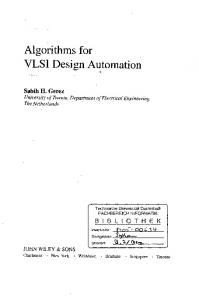
6.1. X mod 5 In this case, observe that the modulo is of the type 2k ? 1 with k = 2. The implementation of hX i5 is based on the partition method. The number X whose size is 16-bits (excluding the P P sign), is partitioned into two blocks V0 and V1 such that V0 = 7i=0 2i xi and V1 = 7i=0 2i xi+8 are two 8-bit numbers. Here s = 8, � = 2, � = 4 and � = 2. Applying eqn. 13, we obtain hX i5 = hhV0i5 + hV1i5 i5 The output from the two blocks are exported to a residue adder to obtain the final result hX i5. The recursive method is used to compute the residues of each of the two partitions, namely, hV0i5 and hV1i5 . These terms are calculated using eqn. 8 such that
hV0i5 = hY0 ? Y1 + Y2 ? Y3 i5 hV1i5 = hY4 ? Y5 + Y6 ? Y7 i5 P where Yi = 1j 0 x2i j 2j , i 2 f0; : : :; 7g. A block diagram for computing hV0 i5 is illustrated in Fig. 4. =
+
The key components of this schematic include 2-bit subtractor/adder modules, register interfaces, a sign update module, a zero
6. Implementation
15
F (x) : P ! Q P Q hX i6 hX i2hX i3
Table 1
0 1 2 3 4 5
00 11 02 10 01 12
condition detect and negative modulus correction circuitry corresponding to procedure Residue discussed earlier. The grouping of bits for array reduction is shown in the top right of Fig. 4. This design has 4 stages with each stage having a delay approximately equal to that of a 2bit adder/subtractor unit. The implemented circuit is non-pipelined. However it can be easily pipelined with the addition of register modules at every stage.
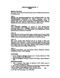
6.2. X mod 7 The modulo is of type 2k ? 1 with k = 3 and hX i7 = hY0 + Y1 + Y2 + Y3 + Y4 + Y5 i7 where Yi = P2j=0 x3i+j 2j , i 2 f0; : : :; 4g and Y5 = x15. Fig. 5 pictorially illustrates the organization of the various blocks of the X mod 7 circuit which uses the recursive approach and consists of 6 stages.
6.3. X mod 6 We follow the technique presented in Section 2.4 to compute X mod 6 using the RMF. The number 6 can be expressed as the product of two relatively prime factors, m1 and m2 where m1 = 2 and m2 = 3. Therefore, hX i6 can be computed if hX i2 and hX i3 are known. From eqn.(2) and k = 1, we obtain hX i2 = x0 where x0 is the least significant bit. hX i3 (where 3 is expressed in the form 2k ? 1 = 22 ? 1) can be evaluated using either of the partition or recursive methods. We chose the partition method with two 4-bit partitions to extract hX i3 . Table 1 gives the RMF defined by eqn. 9 for synthesizing hX i6 and the required boolean logic can be derived easily from hX i2 and hX i3. Likewise, hX i10 can be synthesised from hX i2 and hX i5 through a ROM.
16
Residue extractor
s
7
5
3
1
0
**
**
**
**
Y3
Y2
Y1
Y0
2
2
2
Array reduction
2
2-bit Subtractor sign
V0 (8 bits + sign bit)
** ** ** **
2-bit Subtractor sign
(1:0)
(1:0)
Register module 2-bit Adder/Subtractor sign
sign ** sign **
(3:0) sign
SIGN UPDATE MODULE
*
(3 bits)
**
sign
***
(1:0)
(2)
2-bit Subtractor ** * ** SIGN UPDATE MODULE
(1:0)
**
(2 bits)
sign
Zero detection, negative number residue correction module (1:0)
V0 mod 5 Figure 4 Schematic diagram of individual bits of the operand).
V0 mod 5 unit where V0 is an 8-bit number.
(’*’ denotes the
AAAAAAAAAAAAA AAAAAAAAAAAAA AAAAAAAAAAAAA s
15
14
11
8
2
0
*
***
***
***
***
***
Y5
Y4
Y3
Y2
Y1
Y0
3
3
3-bit Adder MSB
5
(3)
3
3
3-bit Adder
X (16 bits + sign bit) Array reduction
3
*** *** *** *** *** *
3-bit Adder
(3)
(1:0)
6. Implementation
(1:0)
(3)
(2)
(1:0)
Register module FA
3-bit Adder
FA
Cin
* *** * *** * ***
(1) (0)
(3:1)
3-bit Adder
*** * * *** * *** *
HA
** *** *
HA (5)
(4)
(3)
(2)
* * *
Y1
(1)
(0)
* * * 3
3
(6 bits)
Y0
3-bit Adder (3)
(2:0)
* * * *
(4 bits)
3-bit Adder (2:0)
(3 bits)
Sign update, Zero detection, negative number residue correction module (2:0)
X mod 7
Figure 5 Schematic diagram of X mod 7 unit where X is a 16-bit signed integer.
17
18
Residue extractor
Table 2 Statistics of the implemented 16-bit residue extractor Technology Area of the chip No. of pins No. of transistors Measured Propagation delay Dynamic Power dissipation/Mhz
Table 3
3� CMOS3DLM 4545.1x4545.1 �2 m 38 5156 108.6ns 30mwatts
AC characteristics of the residue extractor
Output Group MOD10 MOD9 MOD7 MOD6 MOD5 MOD3
Max. Propagation Delay 108.6ns 108.3ns 107.9ns 75.4ns 104.7ns 62.3ns
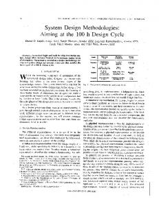
6.4. VLSI Chip The micrograph of the implemented 16-bit residue extractor is shown in Fig. 6 and some related technical details are summarized in Table 2. The performance of the chip was characterized by clocking input data at a period of 200ns (non-pipelined case). A timing analysis was conducted on the chip using an automatic test equipment. The measured worst case delay of the sub-units of the chip are detailed in Table 3. With a maximum delay of approximately 109ns, the chip gives a throughput in excess of 9 million operations per second (MOPS).
7. Discussion Notwithstanding the tremendous progress in contemporary VLSI memory technology, ROM based techniques [6] are expensive and infeasible for large operands since memory requirements increase exponentially with operand length. In this work, we have proposed two new VLSI architectures for implementing X mod m for m = k ? 1 or k + 1 and presented a practical and scalable hardware circuit for for the binary number system. We have also shown that the range of m can be extended using the CRT. In most practical cases, the representative length of the operand X is larger than that of m. Hence, the ROM’s cost for implementing the RMF will be less expensive
7. Discussion
Figure 6
19
Micrograph of a 16-bit residue extractor implemented in 3 �m CMOS3DLM technology
20
Residue extractor
Table 4
m 2 3 4 5 6 7 8 9 10 11 12 13 14 15 16 17
Synthesis method of X mod m for typical values of m � 33. Type 2k (k = 1) k 2 ?1 (k = 2) k 2 (k = 2) k 2 +1 (k = 2) (hX i2; hX i3) CRT(2,3) 2k ? 1 (k = 3) k 2 (k = 3) k 2 +1 (k = 3) (hX i2; hX i5) CRT(2,5) – (hX i3; hX i4) CRT(3,4) – (hX i2; hX i7) CRT(2,7) 2k ? 1 or (k = 4) (hX i3; hX i5) CRT(3,5) 2k (k = 4) k 2 +1 (k = 4)
m 18 19 20 21 22 23 24 25 26 27 28 29 30 31
Type (hX i2; hX i9) CRT(2,9) – (hX i4; hX i5) CRT(4,5) (hX i3; hX i7) CRT(3,7) (hX i2; hX i11) CRT(2,11) – (hX i3; hX i8) CRT(3,8) – – – (hX i4; hX i7) – (hX i5; hX i6) CRT(5,6) 2k ? 1 (k = 5)
32 33
2k ? 1 2k + 1
(k = 5) (k = 5)
compared to a complete look-up. In Table 4, we summarize a typical moduli set that can be implemented using the schemes discussed in this paper for small values of m. The prime factors of m which are synthesizable through the CRT are given in brackets for clarity. The proposed structures, in addition to their regularity and modularity, have significant advantages in terms of speed and area over the model proposed in [7]. It has been reported that the VLSI circuit designed by Alia et al. [7] for integer modulo m operation has a response time of less than 200 ns for 32-bit numbers. The area and time complexity of their architecture is given as O(n2 =TM2 ) and O(TM ) respectively when TM is in the range [log n; pn]. It has been shown in this paper that the time complexity for the two methods is in the range [O(log n); O(log n log log n)] while the area complexity is in the range [O(n); O(n log n)]. The measured propagation delay in our circuit for 16-bit input operands is less than 109ns in 3 � CMOS technology. Our design uses high speed carry look ahead adders [20] and does not involve any multipliers as advocated in [7]. Furthermore, the proposed structures can handle signed integers and are amenable for pipeline implementation. Hence, wider operand range and higher throughput can be realized. The demerits of our model are its restricted range for m and the inability to compute residues of prime numbers which are not of the form 2k ; 2k � 1 in contrast to the generalized approach of [7].
8. Conclusion
21
8. Conclusion The technological advantages of VLSI has made RNS implementation a viable proposition in terms of speed, cost, power dissipation and chip density. The basic contribution of this work is the design approach for calculating X mod m when m is of the form k ; k � 1. Two algorithms, namely the recursive and partition methods have been proposed and expressions for the asymptotic VLSI complexity for their implementation have been derived. The methodology discussed in this paper has been practically applied in the design of X mod m arithmetic units for a port selector module in a 1 :2�m CMOS Hypercycle routing chip [21] where X is a 16-bit operand with m = 2; 3; 4. The cases m = 2; 4 are straightforward while the X mod 3 unit has been implemented using the recursive approach for 4-bit partitions with a two level residue adder tree. The throughput of the residue extractor module in the above chip exceeds 50 MOPS as evidenced by timing simulation results. Technological scaling and pipeline implementation will provide a many-fold increase in the performance of the residue extractor. Additionally, the algorithms proposed here can be extended to non-binary systems when multi-level logic circuits become viable for implementation. Other interesting applications of this work include design of circuits for constant division algorithms [22].
22
Residue extractor
Acknowledgement The authors wish to thank the Canadian Microelectronics Corporation for its assistance in fabricating the VLSI chips discussed in this paper. They also acknowledge Mr. K. Jones, Mr. W. A. Keddy, Mr. R. Kelly, Mr. T. Gore and Mrs. A. Neville for their technical help in the VLSI/Microelectronics laboratory. The authors thank the reviewers for their useful suggestions which have greatly improved the clarity and presentation of this work. The financial support of the Natural Sciences and Engineering Research Council of Canada and the Institute for Robotics & Intelligent Systems of the National Network of Centres of Excellence is gratefully acknowledged.
References [1] F. J. Taylor, “Residue Arithmetic: A tutorial with examples", IEEE Comp., May 1984, 17 (5), pp. 50-62. [2] A. V. Curiger, H. Bonnenberg, and H. Kaeslin, “Regular VLSI Architectures for multiplication Modulo (2n + 1)", IEEE J. Solid-State Circuits, 1991, 26 (7), pp. 990-994. [3] W. K. Jenkins, and B. J. Leon, “ The use of residue number systems in the design of finite impulse response digital filters", IEEE Trans. Circuits Sys., 1977, CAS-24, pp. 191-201. [4] M. A. Soderstrand, “A high speed low-cost recursive digital filtering using Residue Arithmetic", Proc. IEEE, July 1977, 65, pp. 1065-1067. [5] C. H. Huang, D. G. Patterson, H. E. Rauch, J. W. Teague, and D. F. Fraser, “ Implementation of a fast digital processor using the residue number system", IEEE Trans. Circuits Sys., 1981, CAS-28, pp. 32-38. [6] M. A. Bayoumi, G. A. Jullien, and W. C. Miller, “A VLSI model for Residue Number System Architectures", Integration, 1984, 2, pp. 191-211. [7] G. Alia, and E. Martinelli, “A VLSI Structure for X(mod m) Operation", Journal of VLSI Signal Processing, 1990, 1, pp. 257-264. [8] F. J. Taylor, “A VLSI residue arithmetic multiplier", IEEE Trans. Comp., 1982, C-31, pp. 540-546. [9] N. S. Szabo, and R. I. Tanaka, Residue Arithmetic and its Applications to Computer technology, McGraw Hill, New York, 1967. [10] J. H. Mcclellan, and C. M. Rader, Number Theory in Digital signal processing, Prentice Hall, New York, 1979. [11] S. Waser, and M. Flynn, Introduction to Arithmetic for Digital System designers, Holt, Rinehart and Winston, Chicago, 1982, pp. 55
23
[12] R. L. Graham, D. E. Knuth, and O. Patashnik, Concrete Mathematics: A Foundation to Computer Science, Addison-Wesley, Reading, Massachusetts, 1989, pp. 126-133. [13] D. E. Knuth, The Art of Computer Programming : Seminumerical Algorithms, vol. 2, Addison-Wesley, Reading-Mass 1981, pp. 248-256. [14] J. Wakerly, “Error Detecting Codes, Self-Checking Circuits and Applications" in Computer Design and Architecture Series, (North-Holland, 1978), pp. 71-74 [15] J. D. Ullman, Computational Aspects of VLSI, Computer Science Press, Maryland, 1984. [16] S. Dormido, and M. A. Canto, “Synthesis of generalized parallel counters", IEEE Trans. Comp., Sept 1981, C-30, pp. 699-703. [17] K. Efe, “Multi-Operand Addition with conditional sum logic" in Proc. 5th Symposium Comp. Arith., Ann Arbor, May 1981, pp. 251-255. [18] L. Dadda, “Multiple Addition of Binary Serial numbers", Proc. 4th Ann. Symp. Comp. Arith., Long Beach, 1978, pp. 140-148. [19] M. Dugale, “VLSI implementation of Residue Adders based on binary adders", IEEE Trans. Circ. and Sys., May 1992, vol. 2, 39, pp. 325-329 [20] R. P. Brent, and H. T. Kung, “A Regular Layout for Parallel Adders", IEEE Trans. Comp., March 1982, C-31 (3), pp. 260-264. [21] N. J. Dimopoulos, D. Radvan, and R. Sivakumar, “Implementation of Routing Engine for Hypercycle based Interconnection Networks", Proc. 1991 Canadian Conf. on VLSI, Kingston, Aug. 1991, pp. 6.4.1-6.4.7. [22] P. Srinivasan, and F. E. Petry, “Constant Division Algorithms", IEE Proc. Comp. and Digital Tech., Nov 1994, vol. 141 (6), pp. 334-340.