Microcontrollers hybrid network for distributed instrumentation, F. Córdoba Montiel, et al, 179-188
MICROCONTROLLERS HYBRID NETWORK FOR DISTRIBUTED
INSTRUMENTATION
F. Córdoba-Montiel, S. F. Hernández-Machuca & D. Hernández-Ventura Universidad Veracruzana Facultad de Instrumentación Electrónica y Especialización en Sistemas Microprocesadores, Zona Universitaria S/N, C.P. 91050; Xalapa, Ver. Tels: (228) 8-42-17-46 y 8-12-09-46, E-mail:
[email protected],
[email protected],
[email protected] th
th
Received: January 9 2002 and accepted April 30 2003
ABSTRACT
In this work the proposal of an hybrid microcontroller network is presented, whose main application is oriented towards the implementation of a functionally distributed system, which is commanded from a personal computer (PC), where a program developed for the Windows graphical environment is executed and acts as System Monitor supervising the events related to the indebted operation of the network, unfolding numerically and graphically from the information that handles to node level and the present status of the network. The network was implemented under the common bus topology and the application includes the physical layer handling under the RS-485 standard used in the connection between each considered microcontroller node, as well as different microcontroller families such as Motorola, Microchip and the AVR of ATMEL are used. KEYWORDS: Microcontrollers, Distributed Systems, Microcontroller Netwok
1. INTRODUCTION The existence of systems that demand schemes where two or more processing elements take part, originate the necessity to develop specific mechanisms and proposals that satisfy the different applications that mainly appear in the instrumentation and control areas. In that sense, distributed instrumentation plays an important role, since it allows the design of solutions where a problem, that by its own nature cannot be solved with a single device of processing, is fragmented in such way that more process units are added where every one takes part as an individual task, and as a whole solves a unique problem. This exposition suggests that between the different elements that compose the distributed system exist connections at both physical and logical level. Therefore, the mentioned interrelation takes place through a network composed by processing elements that participate in the solution of the problem. The work elements consist of microcontrollers circuits, which by themselves act as specialized systems that internally contain some peripheral resources that facilitate their work and their relation with the outer world. It is possible to emphasize the benefits that a network scheme offers in the solution of specific problems and the advantages that the elements taking part in the network report in their design and construction, both are based in microcontrollers. Thus the exposition of a microcontroller network applied to the functionally distributed instrumentation arises. 179
Journal of Applied Research and Technology
Microcontrollers hybrid network for distributed instrumentation, F. Córdoba Montiel, et al, 179-188
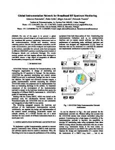
Starting from the fact that not all the work loads, that results from dividing the problem, are homogenous, it is interesting to combine different technologies where the diversity of microcontrollers and the potentialities that each manufacturer implements in its different models allow choosing the most appropriate device according to the requirements that the application demands. From the last propositions, is important to think in an hybrid network (different types from microcontroller) that works in transparent way to the user. 2. EXPOSITIONS From now on each one of the units that constitute the network will be called node. The diversification of the microcontroller’s nodes that compose the network derives from the fact that the assigned service load for each node demands that the associated microcontroller counts on with sufficient peripheral resources to carry out the functions that have been distributed to it, and that they are usually of different nature for each node. Furthermore all of them have the obligation to take care of the communication events that are generated in the network in an opportune and efficient way, and without reduction of the tasks of instrumentation, control and/or sense duties that are carrying out. The design of the network also incorporates schemes of fault tolerance, definition of the data format that is being handled, generic adaptability, synchronization, scalability and generic functions, among them those of the system initialization in remote way via PC, and those that correspond to every node in individual form. The proposal includes the protocol definition and the commutation between the half and full duplex communication way, as well as some variations that help the communication at electrical level. 3. NETWORK TOPOLOGY When one speaks of microcontroller networks, the topologies that have a more reliable operation are daisy chain and common bus. Figure 1 shows a basic network that uses a topology of common bus. We are using this topology because it is the most widely applied in instrumentation tasks.
Figure 1. Common bus topology for the Microcontrollers network
Vol. 2 No. 2 August 2004
180
Microcontrollers hybrid network for distributed instrumentation, F. Córdoba Montiel, et al, 179-188
4. ASPECTS OF ASSOCIATE CIRCUITRY For the communication among the nodes of the network (Fig 2), the RS-485 standard is used. The use of this format presents the advantage that the nodes can be microcontrollers, PC's or any device that has serial asynchronous communication capabilities. The main advantages of the RS-485 are that the protocol and circuitry requirements are simpler and cheaper than other alternatives.
Figure 2. Network electrical diagram
181
Journal of Applied Research and Technology
Microcontrollers hybrid network for distributed instrumentation, F. Córdoba Montiel, et al, 179-188
4.1 Analysis of the microcontrollers which participate in the hybrid network For the implementation of the microcontrollers network is not required that all nodes conforming it be of the same mark or model. The only requirement is that the microcontroller is able to communicate on RS-485 standard and fulfills the requirements of the chosen communication protocol. This stage was orchestrated with the elements that appear in table I. Table I. Microcontrollers in the network Model
Company
AT90S2313 AT90S4415 AT90S8515 AT90S8535 PIC16F877 68HC11
Atmel Atmel Atmel Atmel Microchip Motorola
Available peripheral for asynchronous serial communication (internal) UART UART UART UART USART UART
It is important to point out that if a network is implemented entirely with equal microcontrollers, it is enough to configure one node for the communications system and the result could be extensive for the remaining nodes. The difference among them will be at code level only, based on the activities that have been assigned to them. On the other hand, there are cases when all the nodes are not necessarily equal in their reference, as in the case of this work, although in some situation they can be from the same manufacturer as it happens with the Atmel AVR devices, where 4 different microcontroller models were used. A microcontroller of the Microchip company and one more from the Motorola company were included as well. The manufacture implementation technology of the several microcontrollers used presents important differences. In the internal architecture, a contrast exist between the Von Neumann Technology implemented in the 68HC11, and the typical Harvard architecture in the PIC's and the AVR's. Another important difference is directly related to the communication in the network and it refers to the fact that all the microcontrollers listed in table 1 include, inside their internal available peripheral modules, one for the asynchronous communication series, typically represented by a UART. This is not an indispensable requirement and it can be used, for example, a PIC16F84 microcontroller that implements the functions of a UART by means of software techniques and where two of their Input / Output pins can be used as transmitter and receiver. Each one of the microcontrollers has its operation philosophy for the handling of the pins in charge of the serial communication and its own configuration registries for information transfer. For the 68HC11, the SCI (Serial Communication Interface) is used, that is a powerful UART with superior capacities to those of the other microcontrollers in the communications line. The PIC16F877 in turn, contains a USART that should be configured in asynchronous operation. The ATMEL AVR's participates with their own blocks of asynchronous communication series (UART´s). For the serial communications events in the RS-485 bus, the synchronization aspect becomes a very important factor to consider. Certain time delays should be introduced during their data transmission and reception process that will depend on each microcontroller node to assure that these events happen successfully.
Vol. 2 No. 2 August 2004
182
Microcontrollers hybrid network for distributed instrumentation, F. Córdoba Montiel, et al, 179-188
4.2 Standard RS 485 A RS-485 network consists of multiple devices whose amount can be up to 32 elements (nodes), which communicate through a pair of cables plus an earth reference signal. The number of elements and the maximum length in the network can be extended by using repeaters. In compliance with RS-485 standard specifications, in a multiprocessor system, all the elements that conforms it have the capacity to transmit, nevertheless a single one can do it simultaneously. The data that travel by the RS-485 network do it in form of differential electrical signals. By using differential signals the bus is less sensible to the electromagnetic interferences, as well greater distances can be reached in comparison with the systems that do not use differential methods. All this added to the use of twisted pair as average transmission medium offers several advantages on other communication lines. These communication systems that transmit, data as electrical signals, whose value is referred to earth point, are known as no balanced systems. An example of this is the RS-232 standard whose signals of input and output are referred to their GND terminals or earth (zero volts). On the other hand, the differentials or balanced systems (like the RS-485 standard), transmit their data like a signal of voltage through a pair of conductors. The receiving differential evaluates the voltage present in the line to determine if it is 1 or 0. Although normally the balanced systems have a reference line, this is not used to determine the value of the received bit. The integrated circuit that was used for the handling of the RS-485 network was the SN75176, made by Texas Instruments, which internally contains a transmitter, a receiver, direction control and two pins for interface signals. 4.3 RS-232 / RS-485 Adapter All the microcontroller nodes use two RS-485 drivers that are in charge of converting of turning TTL levels, coming from the microcontrollers, to the differential voltages required by the standard of communication (and vice versa), for transfer of information through the common bus. However, at the exit of the serial PC ports, the signals are generated in the levels defined for the RS-232 standard (+12 -12 volts). In turn, when information is sent from the PC towards the network the first step is to convert RS-232 signals to TTL levels. This is accomplished by using a MAX232 circuit. When these levels are obtained, they are injected to a RS-485 driver that will transfer them to the appropriate differential voltages. The process of information reception from the nodes towards the PC is inverse to that previously described. The adapter circuit constructed consists of two RS-485 drivers, one used like receiver and the other like transmitter, as well as of a MAX232 circuit (RS-232 driver), discrete components like capacitors, resistors, and an external power supply. 4.4 Commutation between Half and Full Duplex The commutation between the half and full duplex communication is made by programming, through the control lines connected to SN75176 (RS-485 drivers) circuits. Table II contemplates the possible configurations using the main bus, the assistant bus or both.
183
Journal of Applied Research and Technology
Microcontrollers hybrid network for distributed instrumentation, F. Córdoba Montiel, et al, 179-188
Table II. Configuration of Network elements STATES Z Impendance Hihg HDR Half Duplex Receiver HDT Half Duplex Transmiter HDR Aux Half Duplex Auxiliary Receiver HDR Aux Half Duplex Auxiliary Transmiter FD1E Full Duplex Slave FD2M Full Duplex Master
RE 1
DE 1
RE 2
DE 2
1
0
1
0
0
0
1
0
1
1
1
0
1
0
0
0
1
0
1
1
0
0
1
1
1
1
0
0
5. COMMUNICATION PROTOCOL The communication protocol defines the rules for the transmission and reception of information between the nodes of the network. Thus for two or more nodes to be able to communicate to each other, it is necessary that both use the same protocol. Due to concerns on protocols that govern network behavior, rehearsals have been made in Master - Slave configuration where all the actions are commanded from a PC and can be directed towards a specific node or to all the elements that compose the network. Also the “Token Passing” protocol has been used to allow a “multi – master” scheme in which each node (in a exclusive way) can behave like Master in the time interval when it has all the faculties to transmit through the bus if required, then yielding the control to another node in a predefined sequence. The transference of information, independently of the network topology, is made by means of messages that can be of a predetermined fixed length or of variable size. For the distributed network both options were developed. In figure 3 a basic example of the variable length protocol used is shown.
Figure 3. Messages of variable length The first message byte corresponds to the identification number of the node to which the message goes to, and the second is the number of the node that is sending the message. The third byte corresponds to the length of the present message. Normally the microcontrollers are taking care of the activities that have been delegated to them in the distribution of tasks. The moment that a message is sent to the bus, all the nodes listen to it, but they must have the capacity to discriminate if the present message is for them or not. Figure 4 shows the flow chart of the subroutine that takes place when the interruption by the arrival of data in the serial channel appears in the microcontrollers. At the moment that the third byte is received, each node verifies if the message is for it. If its ID corresponds, then it will be in charge to receive the number of bytes of the message, indicated at the third locality, where the length of the message is deposited.
Vol. 2 No. 2 August 2004
184
Microcontrollers hybrid network for distributed instrumentation, F. Córdoba Montiel, et al, 179-188
The ISR (Interrupt Service Routine) for all the microcontrollers participating in the network has the structure shown in the algorithm of figure 2. It is important to make the following considerations: • This ISR takes care of messages of variable length, where (while flow of information in the lines of communication does not exist) each node will be dedicated to the accomplishment of the tasks that have been assigned to him previously. • All the microcontroller nodes have a buffer (memory zone) where they deposit the information that they will transmit when the corresponding permission is granted, situation that will depend on the used protocol. Similarly, there is a buffer for the reception of information originated by elements that compose the network. • When there are not messages traveling in the lines, the flags and the counters that help during the reception process are initialized and disabled. The sequence of activities made by the nodes when a message appears is explained briefly and corresponds to the flow chart of figure 4: 1. At the moment that a first byte that acts like a message head is sent, all the nodes receive it because their ISR are activated, interrupting the main program flow in execution and performing the activity that is required. In this case, they store this data in the first locality (locality 1 in the diagram) of the reception buffer and the counter, which is a memory locality that is being used to determine the moment that the three first bytes have been received, is increased (initially, the counter value is equal to zero). As is shown in figure 3, this data corresponds to the node that the message goes to. 2. The second byte is the data of the node that sends the message and is deposited in locality 2 of the buffer. The counter is increased in one. The third byte contains the information of the length of the message. When it is received, it is stored in the following locality and the counter is increased. At this moment the counter value is equal to 3, the node will determine if the message is for it, by comparing its ID with the data stored in locality 1 of the buffer. If they are equal it means that the message is indeed for it, a flag (“bandera_1”, which is a locality or a registry depending on the microcontroller) will activate with a value of ' 1 ', that will indicate that all the other data (amount indicated in locality 3 of the buffer), must be stored consecutively. If the information is for another node, the remaining bytes of the message will be ignored. At this moment a flag indicates that a message is in progress ("Message in course = yes"). 3. Successively, when new data arrives, the node verifies if a message is being received (asking for the flag used for such aim). If that is so, the following step consists on determining if this message should be taken into account asking the value of “bandera_1”. As it was mentioned in the previous point, depending on this value, the data will be stored in the buffer or will be ignored. Whenever data is received, the content of locality 3 (length of the message) will be decreased. 4. Finally, in both cases, when the last byte of the message is received (locality 3 = 0), and the errors detection has been made (through a specific algorithm), “bandera_2” flag activates to indicate to the main program that the message has concluded and the flags and counters are reinitialized in the reception process waiting for a new message to appear.
185
Journal of Applied Research and Technology
Microcontrollers hybrid network for distributed instrumentation, F. Córdoba Montiel, et al, 179-188
Figure 4. Algorithm to attend to the ISR Vol. 2 No. 2 August 2004
186
Microcontrollers hybrid network for distributed instrumentation, F. Córdoba Montiel, et al, 179-188
5.1 Master – Slave Protocol This protocol was the first one implemented for the distributed network and it consists basically of a centralized system where the master node was represented by the PC and the microcontrollers acted as slaves nodes. The sequence of events initiated when the user accessed the network elements arming a variable message of fixed size or as the one previously described thus running consultation functions or exercising some of the functions implemented for some specific node. Working like this, the communication between the slave nodes does not exist and none of them can send information to the master node without previous authorization. 5.2 Token Passing Protocol This appears like a multi - master scheme, where all the network nodes can be master (but not all simultaneously) during a determined time interval, when they can transmit or require information in the bus. When their management as main node ends, they will give to the following node the control of the network, in a sequence defined previously. This alternative presents the problem that, if one (or several nodes) for whatever reason are disabled, and the node that at such time behaves as master must yield the control to one of the elements that are inactive, then a blockade of the activities takes place, neutralizing the system with it. It is in these cases where the schemes of faults tolerance have relevance. For the previously described situation, the solution is that before yielding the control to a node, the master must make a verification of the existence of the microcontroller who will take its place. The master node verifies that exist a candidate to take charge of the network. Once the message is sent, the master will wait for an answer. If an answer does not exist once a predefined counter has expired, the master node will send a new verification message to the node that follows in a sequence, doing that until it finds the next operative node. 6. CONCLUSIONS The most interesting benefit that the implementation of a hybrid network offers is the enrichment of the potentialities of a network of microcontroller elements that, combining different technologies, allow the development of distributed systems in accordance to the necessities specified for diverse applications. 7 REFERENCES [1] [2] [3] [4] [5] [6] [7] [8] [9] [10] [11] [12]
Goscinski A. “Distributed Operating Systems: The Logical Design”, Editorial Addison-Wesley,1991. Nutt, G. J. “Centralized and Distributed Operating Systems”, New Jersey Editorial Prentice Hall Int.,pp 418 1992. Laplante, P. “Real-Time Systems Design and Analysis: an Engineer’s Handbook“, IEEE Press. 1993. “MC68HC11, Reference Manual “, Motorola Inc., 1991. “AVR RISC Microcontroller“, Atmel Corporation, 1999. “Microchip PIC16F87X “, Microchip Technology Inc., 1999. “ SN75176 Diferential Bus Transceivers”, Texas Instruments Inc., 1999 “MC68HC11EVBU, Universal Evaluation Board User’s Manual”, Motorola. First Edition, 1990. Ceballos Sierra, F. J. “Enciclopedia de Microsoft Visual Basic 6.0”, Editorial Addison-Wesley Iberoamericana. Axelson, J. “Designing RS-485 Circuits”, Cicuit Cellar, Issue 107 June 1999, www.circuitcellar.com. Axelson, J. “Networks for Monitoring and Control Using an RS-485 interface”, Microcomputer Journal, 1995. Perrin, B. “The Art and Science of RS-485”, Cicuit Cellar, July 1999, www.circuitcellar.com.
187
Journal of Applied Research and Technology
Microcontrollers hybrid network for distributed instrumentation, F. Córdoba Montiel, et al, 179-188
Authors Biography
Sergio F. Hernández Machuca Was born in Xalapa, Veracruz, México in Octuber 7th 1957. Got a B.Sc. degree in Industrial Electronics from Instituto Tecnológico de Veracruz (1975 – 1978), graduated in 1981. Got a M.Sc. degree in Electronics Engineering (Microprocessors) in Centro de Graduados del Tecnológico de Chihuahua (1979 – 1981). He worked as full time professor in Tecnológico de Veracruz (1981 – 1982), Tecnológico de Chihuahua (1982 – 1986) and Universidad Veracruzana, (Faculty of Electronic Instrumentation) since 1986 until today. Has been Principal of the Physics Faculty (Universidad Veracruzana, 1991 – 1992) and Electronic Instrumentation Faculty (Universidad Veracruzana, 1992 – 1993). Coordinator, Research advisor, and instructor in the graduate program “Especialización en Sistemas Microprocesadores” (Universidad Veracruzana, from 1997 until today). Advisor over 30 thesis works in bachelor and specialization degree (electronics, instrumentation and computation areas). His main interest areas: Microprocessors applications, computer languages, digital systems.
Francisco Córdoba Montiel He was born in Xalapa, Veracruz, México in 1972. He graduated in Electronic Instrumentation Engineering from the University of Veracruz, México, 1998. His specialty is in Microprocessor Systems at the University of Veracruz, 1999. He is currenly in charge of the network of seismic and volcanic monitoring at the Center of Sciences of the Earth where he works in the investigation of sismology. He is professor in the Faculty of Electronic Instrumentation at the University of Veracruz, and of Computer Systems at the Atenas Veracruzana University. His main themes of interest are systems based on microprocessors and microcontrollers applied in tasks of instrumentation and control.
Daniel Hernàndez Ventural He was born in Xalapa, Veracruz, México in 1976. He graduated as Electronic Engineer from the Instituto Tecnologico de Veracruz, México, 1994. His specialty is in Microprocessor Systems at the University of Veracruz, 2000. He is a university professor in the Instituto Tecnologico Superior de Xalapa, in the speciality of electronic engineering, and Informatics at the Instituto Veracruzano de Educaciòn Superior. His main themes of interest are systems applied in tasks of instrumentation and control, based on microprocessors and microcontrollers, linux’s applications oriented to the education
Vol. 2 No. 2 August 2004
188