Jun 7, 2016 - and the circle whose radius is equal to the distance between between ... Beginning with the odd topology, choose a polar coordinate system (r, θ) such that its pole ... the centre of the auxiliary circle from the Melzak algorithm.
MINIMAL CURVATURE-CONSTRAINED NETWORKS
arXiv:1606.02026v1 [math.MG] 7 Jun 2016
D. KIRSZENBLAT, K. SIRINANDA, M. BRAZIL, P. GROSSMAN, J. H. RUBINSTEIN, AND D. THOMAS Abstract. This paper introduces an exact algorithm for the construction of a shortest curvature-constrained network interconnecting a given set of directed points in the plane and an iterative method for doing so in 3D space. Such a network will be referred to as a minimum Dubins network, since its edges are Dubins paths (or slight variants thereof). The problem of constructing a minimum Dubins network appears in the context of underground mining optimisation, where the aim is to construct a least-cost network of tunnels navigable by trucks with a minimum turning radius. The Dubins network problem is similar to the Steiner tree problem, except that the terminals are directed and there is a curvature constraint. We propose the minimum curvature-constrained Steiner point algorithm for determining the optimal location of the Steiner point in a 3-terminal network. We show that when two terminals are fixed and the third varied, the Steiner point traces out a lima¸con.
1. Introduction This paper is concerned with the problem of designing a shortest path network for vehicles. The paths in the network are subject to a curvature constraint that accounts for the minimum turning radius of the vehicles. Interest in such networks is motivated by their relevance for designing the access in underground mines [3]. The Dubins network problem can be viewed as a novel combination of two problems that have been well-studied in the optimisation literature: the Steiner problem and the Dubins problem. What follows is a review of these two problems. Some basic geometric and topological concepts primarily drawn from [5] and [9] are presented here in order to prepare the reader for subsequent sections. First, consider Fermat’s problem, which is a 3-terminal special case of the Steiner problem: Problem 1 (Fermat’s problem). Given three points p1 , p2 , p3 in the plane R2 , find the point s which minimises the sum of the distances ||sp1 || + ||sp2 || + ||sp3 ||. The uniqueness of s, called the Steiner point, is obtained from the convexity of the Euclidean norm. If one of the angles of 4p1 p2 p3 is at least 120◦ , then s is located at its vertex. Otherwise, s lies in the interior of 4p1 p2 p3 , whose sides subtend angles of 120◦ 2010 Mathematics Subject Classification. Primary 90C35; Secondary 49Q10. Key words and phrases. Network optimisation, Optimal mine design, Dubins path, Curvature constraint, Steiner point. 1
2 D. KIRSZENBLAT, K. SIRINANDA, M. BRAZIL, P. GROSSMAN, J. H. RUBINSTEIN, AND D. THOMAS
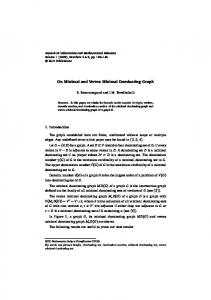
at s. Melzak [10] proposed a ruler and compass construction for finding s in the latter case. Let m be the third vertex of the equilateral triangle with p1 and p2 as its other two vertices, and whose interior lies outside that of 4p1 p2 p3 . Let Γ be the circle through p1 , p2 , m. Then s is the intersection of Γ and the Simpson line mp3 as shown in Fig. 1. p3 s p1
p2
m
Figure 1. Melzak’s construction Based on the above 3-terminal algorithm that substitutes m for p1 and p2 , locates s and adds the straight segments p1 s and p2 s, the Melzak algorithm generalises to n terminals (see [10] for details). The Melzak algorithm yields all the minimising networks of the Steiner problem: Problem 2 (The Steiner problem). Given n points p1 , . . . , pn in the plane R2 , construct a shortest network interconnecting these n points. Some basic moves for constructing a shortest network are as follows. Consider a network S interconnecting n points p1 , . . . , pn , called terminals, in the plane R2 . A Steiner point is any vertex in S other than a terminal. A Steiner point must be of degree at least three. To see this, a degree-1 Steiner point can be deleted along with its incident edge to shorten the network. Also, a degree-2 Steiner point and its two incident edges can be deleted and replaced by a single edge. Splitting a vertex v2 is the operation of disconnecting two straight segments v1 v2 , v2 v3 and connecting v1 , v2 , v3 to a newly created Steiner point s. Shrinking an edge sv2 is the reverse operation which returns the original graph. Suppose that two straight segments v1 v2 , v2 v3 meet at a vertex v2 with an angle less than 120◦ . Then the network can be shortened by splitting at v2 and solving Fermat’s problem for v1 , v2 , v3 in order to locate the new Steiner point s. Consequently, a Steiner point must be of degree at most three. It follows that a Steiner point must be of degree exactly three. Gilbert and Pollak [7] called a local minimum network a Steiner tree. The network is a local minimum in the sense that it cannot be shortened by small perturbation of the Steiner points, even when splitting is allowed. They called a global minimum network a Steiner minimal tree. A simple counting argument shows that a Steiner tree with n terminals has at most n − 2 Steiner points [4]. A Steiner tree with n − 2 Steiner points is called a full Steiner tree.
MINIMAL CURVATURE-CONSTRAINED NETWORKS
3
Now consider the Dubins problem in the plane. It is convenient to introduce some notation. A directed point is a pair (p, #» p ), where p is a point in the plane R2 and #» p is a 2 tangent vector in the tangent space Tp R based at p. For simplicity, such a pair is denoted as p. Given two directed points p1 , p2 , a path connecting these two directed points is called admissible [1] if: (i) It is continuously differentiable. (ii) It starts at p1 and finishes at p2 and has tangent vectors #» p 1 and #» p 2 at these two points respectively. (iii) It is piecewise twice differentiable. There is a finite number of points at which the curvature is not defined. (iv) Where the curvature exists it is less than or equal to a fixed positive number ρ−1 , where ρ is the minimum radius of curvature. Without loss of generality, for the theory we will set ρ = 1 throughout the paper. The Dubins problem can be formulated as follows: Problem 3 (The Dubins problem). Given an initial directed point p1 and a final directed point p2 , construct a shortest admissible path connecting these two directed points. Dubins [5] proved that such a path, called a Dubins path, necessarily exists and consists of not more than three components, each of which is either a straight segment, denoted by S, or an arc of a circle of radius ρ, denoted by C. Furthermore, such a path is necessarily a subpath of a path of type CSC or of type CCC. A well-known result states that if two points p1 and p2 are distance at least 4ρ apart, then a shortest Dubins path between any two directed points (p1 , #» p 1 ) and (p2 , #» p 2 ) is of type CSC (see, for example, [8]). From now on this paper adopts the convention that given two directed points p1 , p2 , a path connecting these two directed points is admissible if the conditions (i), (iii) and (iv) stated above are fulfilled and it has tangent vectors #» p 1 and − #» p 2 at p1 and p2 , respectively, when traveling from point p1 to point p2 . We do not specify a starting point, because none of the terminals in a network can be considered as initial or final when the number of terminals n is greater than or equal to 3. Given three directed points p1 , p2 , p3 in the plane, a network interconnecting these three directed points is called admissible if: (i) It is continuously differentiable except at any Steiner point. (ii) It interconnects p1 , p2 , p3 and has tangent vectors #» p 1 , #» p 2 , #» p 3 at these three points respectively. (iii) It is piecewise twice differentiable. There is a finite number of points at which the curvature is not defined. (iv) Where the curvature exists it is less than or equal to a fixed positive number ρ−1 , where ρ is the minimum radius of curvature. A 3-terminal version of the Dubins network problem can be formulated as follows: Problem 4 (The 3-terminal Dubins network problem). Given three directed points p1 , p2 , p3 , construct a shortest admissible network interconnecting these three directed points.
4 D. KIRSZENBLAT, K. SIRINANDA, M. BRAZIL, P. GROSSMAN, J. H. RUBINSTEIN, AND D. THOMAS
An example of such a network is shown in Fig. 2. By analogy with Steiner trees, a local minimum network is called a Dubins network, whereas a global minimum network is called a minimum Dubins network.
Figure 2. A 3-terminal Dubins network 2. Dubins networks in the plane To simplify the analysis in this paper, we will focus on the full case of the 3-terminal problem. That is, we will focus on the case where the network has three edges of type CS meeting at a Steiner point. On the other hand, the degenerate case is not particularly interesting and consists of a concatenation of two Dubins paths, or a slight modification thereof. Determining the conditions under which the degenerate case occurs is beyond the scope of this paper. We begin our analysis with a preliminary proposition. To this end, it will be convenient to adopt the variational approach from the work of Rubinstein and Thomas [11] on Steiner trees. Proposition 1. Suppose that p1 p2 p3 is a curve of type CS and that p1 is held fixed while p3 is varied. Then the first variation of length of p1 p2 p3 is the negative of the scalar product between the direction of variation and the outward pointing unit vector p3ˆp2 . Proof. Let p1 p2 p3 be a curve of type CS where: • p1 p2 is a circular arc of radius 1. • p2 p3 is a straight segment. p1
p2 n x
p3
Figure 3. A curve of type CS
v’
MINIMAL CURVATURE-CONSTRAINED NETWORKS
5
In Figure 3, the point p3 moves along any smooth curve with derivative at its initial position being the vector v0 . Let L denote the length of p1 p2 p3 . The curve p1 p2 is an arc of a unit circle with centre the origin. The length of p1 p2 is the angle θ subtended by p1 p2 at the origin. Let n ˆ be the unit vector from the origin to the point p2 and x the vector from p2 to p3 , with length denoted by x and unit vector in the direction of x denoted by x ˆ. Observe that the first variation of the vector x is equal to the first variation of its head, i.e. v0 , minus the first variation of its tail, i.e. n ˆ 0 . If the point p3 is perturbed in the direction 0 of v , then the first variation of length of p1 p2 p3 is L0 = θ0 + x0 =n ˆ0 · x ˆ + x0 · x ˆ =n ˆ0 · x ˆ + (v0 − n ˆ0 ) · x ˆ = v0 · x ˆ. � The weighted Dubins network problem is analogous to the Fermat-Weber problem (see, for example, [12]). In the 3-terminal case, let Li denote the length of a CS-path from the ith terminal to the variable Steiner point. The weights wi are the costs per Punit length of the three paths. We seek to minimise the weighted sum of path lengths 3i=1 wi Li . We may appeal to a local argument in order to show that the angles at the junction are the same as those of a similarly weighted Steiner tree. To that end, consider the P 3-terminal case of the Fermat-Weber problem, which is to minimise the weighted sum 3i=1 wi kxi k. Here xi denotes the vector from the ith terminal to the variable Steiner point. We use a ˆ 0i = 0 (differentiate x ˆi · x ˆ i ) throughout variational argument. Noting that x0i = v0 and xi · x 0 the perturbation in the direction of v , we have by the product rule, L0 =
=
=
=
3 X i=1 3 X i=1 3 X i=1 3 X
wi kxi k0 ˆ i )0 wi (xi · x ˆ i + xi · x ˆ 0i ) wi (x0i · x ˆi wi v 0 · x
i=1
= v0 ·
3 X i=1
ˆi. wi x
6 D. KIRSZENBLAT, K. SIRINANDA, M. BRAZIL, P. GROSSMAN, J. H. RUBINSTEIN, AND D. THOMAS
P ˆ i = 0. Mechanically speaking, this means that the At equilibrium we must have 3i=1 wi x ˆ i acting at the Steiner point is zero. An application of the law sum of the forces fi = −wi x of cosines gives the angles αi at the junction in terms of the weights wi . Proposition 2. For any 3-terminal Dubins network whose paths are of type CS, the three Dubins paths meet at angles α1 , α2 , α3 determined as in the case of the Fermat-Weber problem.
s
s v’
Figure 4. A perturbation in the direction of negative gradient will shorten the network. Proof. It suffices to work locally. Fix a small disk around the Steiner point (see Fig. 4 (left)). Fix the points of intersection of the Dubins paths with the boundary of the disk. Within the disk, if the three straight segments do not make angles α1 , α2 , α3 with each other, then move the Steiner point in the direction of negative gradient (see Fig. 4 (right)). (Recall that the gradient is the negative of the sum of the three weighted outward pointing unit vectors.) Finally, replace the newly created angles at the boundary of the disk by small arcs of circles of radius ρ. Note that two length-reducing moves have been made. This shows that the three straight segments meet at angles α1 , α2 , α3 . � We now show that when two terminals are fixed and the third varied, the Steiner point traces out a lima¸con. The lima¸con itself is not required by the algorithm. However, certain geometric constructions (i.e. lines and circles) found in the derivation of the equation of the lima¸con will be used in the algorithm. Assume that all of the paths are of type CS. Choose one Dubins circle for each directed point. (Note that there are eight possible combinations, and that each combination can be considered independently.) Take any two of the Dubins circles. There are two possible Dubins topologies that can arise: an even topology arises when the circular arcs are similarly oriented, and an odd topology arises when the circular arcs are oppositely oriented. For example, the topology shown in Fig. 5 (right) is even, because both circular arcs, i.e. C components incident to p1 and p2 , are clockwise oriented. On the other hand, the topology shown in Fig. 5 (left) is odd. We first need to construct the following circles (see Figures 6 through 8): (i) The auxiliary circle through points c1 , c2 , and s.
MINIMAL CURVATURE-CONSTRAINED NETWORKS
α2 s’
s’
α2
α1
7
α1
α3
α3
c1
c2
p1
p2
c1
c2
p1
p2
m
m
Figure 5. The loci of potential Steiner points for two different topologies (ii) The Melzak circle with centre m. (iii) The circle centred at s and incident to s0 . Only the first and last circles will be used in the derivation of the equation of the lima¸con, whereas all three will be used in the algorithm in section 3. s’ α2 α1
s’ α2 α1
α3 s
s
α3
c2
c1 c1
c2
p1
p2
p1
p2
m’ m
m’ m
Figure 6. The Melzak-like construction for two different topologies
8 D. KIRSZENBLAT, K. SIRINANDA, M. BRAZIL, P. GROSSMAN, J. H. RUBINSTEIN, AND D. THOMAS
In order to determine the auxiliary circle, consider two segments c1 s and c2 s parallel to the first and second paths, respectively, of the sought-after Dubins network. (Refer to Fig. 6) Since the angle c1 sc2 = α3 , by the Inscribed Angle Theorem, s lies on a circular arc of angle 2π − 2α3 through c1 and c2 . Now let d denote the distance between the two Dubins circles with centres c1 and c2 and r the radius of the auxiliary circle through points c1 , c2 , d , and hence r = 12 d csc α3 . and s. Using basic trigonometry, we have sin(π − α3 ) = 2r For either topology, locating the Melzak point m follows the same procedure as in the Fermat-Weber problem [6]. Note that the exterior angles of the triangle c1 c2 m are α1 , α2 , α3 (see Fig. 7). Then this triangle is similar to that formed by the three force vectors fi . Hence the Melzak point m is determined. Let rm and rs denote the radii of the Melzak circle and the circle whose radius is equal to the distance between between the points s and s0 , respectively. In order to determine the radius rm in the case of the odd topology, refer to Figure 8 (left). Observe that rm = rs sin(π − α1 − α�23 ) and 1 = rs sin( α23 ). Eliminating rs and solving for rm we get: rm = sin(α1 ) cot α23 + cos(α1 ). In order to determine the radius rm in the case of the even topology, refer to Figure 8 (right). Observe that rm = rs cos(π − α1 −�α23 ) and 1 = rs sin( π2 − α23 ). Eliminating rs and solving for rm we get: rm = sin(α1 ) tan α23 − cos(α1 ).
c1
α2
α1
m
c2
α3
Figure 7. Locating the Melzak point 0 Finally, we need to determine the distance between between the � � points s and s . Once α3 α3 again, refer to Figure 8. We have rs = csc 2 and rs = sec 2 in the cases of the odd and even topologies, respectively.
Theorem 1. Consider a full Dubins network on three terminals. Suppose that two terminals are fixed and the third varied. Then the Steiner point traces out a lima¸con.
MINIMAL CURVATURE-CONSTRAINED NETWORKS
π - α1 - α3/2
9
π - α1 - α3/2
s’ α3/2 rs rm
1
s
s’
rs
rm
s
π/2 - α3/2
1
Figure 8. Determining the radii rm and rs Proof. Suppose we have determined the angles between the paths of a 3-terminal Dubins network. In particular, suppose the angle between the first and second paths is α. The method for determining the lima¸con (i.e., the locus of potential Steiner points) is as follows. Beginning with the odd topology, choose a polar coordinate system (r, θ) such that its pole is p and the polar axis points toward q. Refer to Figure 9 (left). The point q constitutes the centre of the auxiliary circle from the Melzak algorithm. The point p is the point of self-intersection of the lima¸con. Let d denote the distance between the two Dubins # »0 #» v (θ) = qs, #» and v (θ) = ss circles. The three phasors v1 = pq, are given by 12 d csc α(1, 0), 2 3 � 1 α 2 d csc α(cos 2θ, sin 2θ), and csc 2 (cos θ, sin θ), respectively. This is easy to show using basic trigonometry. Then r(θ) = v1 + v2 (θ) + v3 (θ) �α� 1 1 = d csc α(1, 0) + d csc α(cos 2θ, sin 2θ) + csc (cos θ, sin θ). 2 2 2 After computing the norm of both sides and simplifying, we obtain for the equation of the lima¸con �α� r(θ) = csc + d csc(α) cos(θ). 2 For the odd topology, choose a polar coordinate system (r, θ) such that its pole is p and the polar axis points toward q. The point q constitutes the centre of the auxiliary circle from the Melzak algorithm. The point p is the point of self-intersection of the lima¸con. # »0 #» v (θ) = qs, #» and v (θ) = ss The three phasors v1 = pq, are now given by 21 d csc α(−1, 0), 2 3 � 1 α 2 d csc α(cos 2θ, sin 2θ), and sec 2 (− sin θ, cos θ), respectively. The resulting equation of
10 D. KIRSZENBLAT, K. SIRINANDA, M. BRAZIL, P. GROSSMAN, J. H. RUBINSTEIN, AND D. THOMAS
s’ s’
s
s
p
2θ
2θ
q
q θ
θ p
Figure 9. The graphs of lima¸cons for two different topologies the lima¸con is r(θ) = sec
�α� 2
− d csc(α) cos(θ). �
3. The minimum curvature-constrained Steiner point algorithm in 3D space We now present the minimum curvature-constrained Steiner point algorithm for determining the optimal location of the Steiner point in a 3-terminal network in 3D space. The optimal location of the Steiner point is obtained so as to minimise the total length of the network. An iterative process is introduced to first solve the projected problem in the horizontal plane before lifting the solution to 3D space. The location of the Steiner point is then determined in a plane in 3D space. This process is iterated till it converges to the optimal location. In what follows, we give a more detailed explanation of how to determine the location of the junction in the weighted planar version of the problem for both the odd and even topologies. We then explain how to lift the solution to 3D space. Finally, we explain how to update the weights when projecting the solution back onto a horizontal plane. Solving the problem in the horizontal plane. Determining the optimal location of the Steiner point for the odd topology We begin with the odd topology. Fig. 10 illustrates all the points that we consider when locating the Steiner point in the horizontal plane. 1. Find the three centres c1 , c2 , c3 of the three chosen Dubins circles. These have coordinates (cxi , cyi ) = (xi , yi ) ± (− sin θi , cos θi ) with i = 1, 2, 3, as shown
MINIMAL CURVATURE-CONSTRAINED NETWORKS
11
p’3 p3 c3
t3
s’ α2 α1 α3 s
t1
p’1
t2 c1
c2
p1
p2
p’2
m’ m
Figure 10. Optimal location of the Steiner point for the odd topology in Fig 11. Note that there are two choices of Dubins circle for each directed point. So we need to keep track of eight possible networks and compare their lengths. 2. Find the Melzak point m = (mx , my ). Consider the centres c1 and c2 of p two Dubins circles. The distance d3 between the centres c1 and c2 is given by d3 = (cx1 − cx2 )2 + (cy1 − cy2 )2 . At the first iteration, we take the angles αi with i = 1, 2, 3 at the junction to be equal to 2π/3, in which case the weights wi are equal and 4c1 c2 m equilateral. However, in subsequent iterations, the angles αi with i = 1, 2, 3 will not in general be equal and will need to be determined from the weights wi . We will start with the special case in which the weights wi are equal and return to the issue of computing more general weights later. Since 4c1 c2 m is an equilateral triangle, (cxi − mx )2 + (cyi − my )2 = d23
(1)
for i = 1, 2. By solving Equation 1 for i = 1, 2, we will get two possible solutions for m. We compare the distances from each of the two possible solutions to p3 . The point that gives the maximum distance is picked as the location for m.
12 D. KIRSZENBLAT, K. SIRINANDA, M. BRAZIL, P. GROSSMAN, J. H. RUBINSTEIN, AND D. THOMAS
θ3
p3 c3
c1
θ1 p1
c2
θ2
p2
Figure 11. Possible Dubins circles incident to the given terminals 3. Find the tangent point t3 on circle C3 . The tangent point t3 = (tx3 , ty3 ) is the point where � the Simpson line tangent to the Melzak α3 circle with centre m and radius sin(α1 ) cot 2 + cos(α1 ) is tangent to C3 . At the first iteration, we take the angles αi with i = 1, 2, 3 at the junction to be equal to 2π/3, in which case the weights wi are equal and the Melzak circle degenerates to a point. Now consider two vectors u3 and r3 along the Simpson line and radius of C3 , respectively, where u3 = (tx3 − m0x )i + (ty3 − m0y )j and r3 = (tx3 − cx3 )i + (ty3 − cy3 )j. We obtain the equations (cx3 − tx3 )2 + (cy3 − ty3 )2 = 1 (tx3 − m0x )(tx3 − cx3 ) + (ty3 − m0y )(ty3 − cy3 ) = 0.
(2) (3)
Equation 2 is the equation of the circle C3 . The vectors u3 and r3 are perpendicular, so u3 .r3 = 0, which is expressed in Equation 3. Similarly, consider two vectors u3 and rm along the Simpson line and radius of the Melzak circle Cm , respectively, where u3 = (tx3 − m0x )i + (ty3 − m0y )j and rm = (m0x − mx )i + (m0y − my )j. We obtain the equations �α � 3 (mx − m0x )2 + (m0y − my )2 = (sin(α1 ) cot + cos(α1 ))2 (4) 2 y (tx3 − m0x )(m0x − mx ) + (t3 − m0y )(m0y − my ) = 0. (5) Equation 4 is the equation of the circle Cm . The vectors u3 and rm are perpendicular, so u3 .rm = 0, which is expressed in Equation 5. The coordinates of m0 and t3 can be found by solving simultaneous Equations 2, 3, 4 and 5. 4. Find the point s = (sx , sy ). First calculate the equation of the circle C through the points c1 , c2 , m, in the form of
MINIMAL CURVATURE-CONSTRAINED NETWORKS
13
(x − a)2 + (y − b)2 = r2 . We have (cx1 − a)2 + (cy1 − b)2 = r2
(6)
(cy2
(7)
(cx2 − a)2 +
− b)2 = r2
2
2
2
(mx − a) + (my − b) = r .
(8)
By solving Equations 6, 7, 8, the coefficients a, b, r can be determined. In addition, we have (sx − a)2 + (sy − b)2 = r2 ty3 − m0y sy − my = x . sx − mx t3 − m0x
(9) (10)
Equations 9 and 10 are obtained from the fact that the point s lies on the circle C and the line ms is parallel to the Simpson line m0 t3 . The coordinates of s = (sx , sy ) can be calculated by solving Equations 9 and 10. 5. Find the junction s0 = (s0x , s0y ). The junction s0 lies on the� intersection of the Simpson line m0 t3 and the circle with centre s and radius csc α23 . We have the equations (sx − s0x )2 + (sy − s0y )2 = csc2 (α3 ) s0y − m0y = s0x − m0x
ty3 tx3
− m0y . − m0x
(11) (12)
By solving Equations 11 and 12, the coordinates of s0 can be found. 6. Find the points of tangency t1 , t2 . The point t1 = (tx1 , ty1 ) is the tangent point of the line s0 t1 and Dubins circle C1 . Consider two vectors u1 and r1 along the line s0 t1 and radius of C1 , respectively, where u1 = (tx1 − s0x )i + (ty1 − s0y )j and r1 = (tx1 − cx1 )i + (ty1 − cy1 )j. We obtain the equations (cx1 − tx1 )2 + (cy1 − ty1 )2 = 1 (tx1 − s0x )(tx1 − cx1 ) + (ty1 − s0y )(ty1 − cy1 ) = 0.
(13) (14)
Equation 12 is the equation of the circle C1 . The vectors u1 and r1 are perpendicular, so u1 .r1 = 0, which is expressed in Equation 14. The coordinates of t1 can be found by solving Equations 13 and 14. Similarly, the point t2 = (tx2 , ty2 ) is the tangent point of the line s0 t2 and Dubins circle C2 . Consider two vectors u2 and r2 along the line s0 t2 and radius of C2 , respectively, where u2 = (tx2 −s0x )i+(ty2 −s0y )j and r2 = (tx2 −cx2 )i+(ty2 −cy2 )j. We obtain the equations (cx2 − tx2 )2 + (cy2 − ty2 )2 = 1 (tx2 − s0x )(tx2 − cx2 ) + (ty2 − s0y )(ty2 − cy2 ) = 0.
(15) (16)
Equation 15 is obtained from the radius of C2 . The vectors u2 and r2 are perpendicular, so u2 .r2 = 0, which is expressed in Equation 16. The coordinates of t2 can be found by solving Equations 15 and 16.
14 D. KIRSZENBLAT, K. SIRINANDA, M. BRAZIL, P. GROSSMAN, J. H. RUBINSTEIN, AND D. THOMAS
Determining the optimal location of the Steiner point for the even topology The method is similar to that used for the odd topology, and we abbreviate it somewhat.
p’3 p3 c3 t3
s’ α2 α1
s
α3
t1 c2
c1 p’1
t2
p1
p2 p’2
m’ m
Figure 12. Optimal location of the Steiner point for the even configuration
1. Find the points of tangency m0 and t3 on the Melzak circle and circle C3 , respectively, that determine the Simpson line. � Consider the Melzak circle Cm with centre m and radius sin(α1 ) tan α23 − cos(α1 ), as shown in Fig. 12. The point m0 is such that a line through m0 is tangent to both the circles Cm and C3 . The point t3 = (tx3 , ty3 ) is the tangent point of the Simpson line through m0 and the Dubins circle C3 . Consider two vectors u3 and r3 along the Simpson line and radius of C3 , respectively, where u3 = (tx3 − m0x )i + (ty3 − m0y )j and r3 = (tx3 − cx3 )i + (ty3 − cy3 )j. We obtain the
MINIMAL CURVATURE-CONSTRAINED NETWORKS
15
equations (cx3 − tx3 )2 + (cy3 − ty3 )2 = 1 (tx3 − m0x )(tx3 − cx3 ) + (ty3 − m0y )(ty3 − cy3 ) = 0.
(17) (18)
Equation 17 is obtained from the radius of C3 . The vectors u3 and r3 are perpendicular, so u3 .r3 = 0, which is expressed in Equation 18. Similarly, consider two vectors u3 and rm along the Simpson line and radius of Cm , respectively, where u3 = (tx3 − m0x )i + (ty3 − m0y )j and rm = (m0x − mx )i + (m0y − my )j. We obtain the equations �α � 3 − cos(α1 ))2 (19) (mx − m0x )2 + (m0y − my )2 = (sin(α1 ) tan 2 y (tx3 − m0x )(m0x − mx ) + (t3 − m0y )(m0y − my ) = 0. (20) Equation 19 is the equation of the circle Cm . The vectors u3 and rm are perpendicular, so u3 .rm = 0, which is expressed in Equation 20. The coordinates of m0 and t3 can be found by solving simultaneous Equations 17, 18, 19 and 20. 2. Find the junction s0 = (s0x , s0y ). The point s0 lies on �the intersection of the Simpson line m0 t3 and the circle with centre s and radius sec α23 . We obtain the equations (sx − s0x )2 + (sy − s0y )2 = sec2 (α3 ) s0y − m0y = s0x − m0x
ty3 tx3
− m0y . − m0x
(21) (22)
The coordinates of s0 can be found by solving Equations 21 and 22. Solving the problem in 3D space. 1. Find the lifted points p01 = (x01 , y10 ), p02 = (x02 , y20 ), p03 = (x03 , y30 ). The coordinates of terminals p1 = (x1 , y1 , z1 ), p2 = (x2 , y2 , z2 ), p3 = (x3 , y3 , z3 ) are given. The point p0i with i = 1, 2, 3 is such that |ti pi | = |ti p0i |, where |ti pi | = βi . We have r0i .ri = ||r0i || ||ri || cos βi ,
(23)
from which it follows that � βi = arccos
r0i .ri ||r0i || ||ri ||
� (24)
for i = 1, 2, 3, where ri = (txi − cxi )i + (tyi − cyi )j and r0i = (xi − cxi )i + (yi − cyi )j. In addition, we have (x0i − txi )2 + (yi0 − tyi )2 = |ti p0i |2 = βi2 s0y − yi0 s0y − txi = s0x − x0i s0x − tyi
(25) (26)
for i = 1, 2, 3. By solving Equations 25 and 26, the coordinates of p0i with i = 1, 2, 3 can be found.
16 D. KIRSZENBLAT, K. SIRINANDA, M. BRAZIL, P. GROSSMAN, J. H. RUBINSTEIN, AND D. THOMAS
p’3 p3 c3
t1
p’1
r1
p1
c1
r’1
r’2 r3
t3
t2
r2 c2 r’2 p2
p’2
Figure 13. Locations of the points p01 , p02 , p03 2. Find the plane on which the Steiner point lies. The equation of a plane is given by ax + by + cz = d, where d = ax0 + by0 + cz0 for any point (x0 , y0 , z0 ) in the plane. The normal vector (a, b, c) is determined by the cross product of two vectors, p00 p01 = (x01 − x00 )ˆi + (y10 − y00 )ˆj + (z1 − z0 )kˆ and ˆ That is, a = (y 0 −y 0 )(z2 −z0 )−(y 0 −y 0 )(z1 −z0 ), p00 p02 = (x02 −x00 )ˆi+(y20 −y00 )ˆj+(z2 −z0 )k. 1 0 2 0 0 0 0 0 b = (x2 − y0 )(z1 − z0 ) − (x1 − x0 )(z2 − z0 ), c = (x01 − x00 )(y20 − y00 ) − (x02 − x00 )(y10 − y00 ). The Steiner point lies on the intersection of this plane and the vertical line (s0x , s0y ), hence a(s0x − x0 ) + b(s0y − y0 ) + c(s0z − z0 ) = 0,
(27)
from which it follows that a(s0x − x0 ) + b(s0y − y0 ) . (28) c By solving Equation 28, the z coordinate of the Steiner point can be obtained. 3. Find the gradients of the line segments p01 s0 , p02 s0 , p03 s0 . Three gradients g1 , g2 , g3 [2] are defined for three straight line segments p01 s0 , p02 s0 , p03 s0 and given by Equation 29 for i = 1, 2, 3 respectively. Thus, for i = 1, 2, 3 s0z = z0 −
|s0z − zi | . gi = q (s0x − x0i )2 + (s0y − yi0 )2
(29)
4. Find the weights of edges p01 s0 , p02 s0 , p03 s0 . The weights w1 , w2 , w3 are used to project the solution back onto the horizontal plane. The gradient of a line segment can be used to obtain the weight of the corresponding
MINIMAL CURVATURE-CONSTRAINED NETWORKS
17
0 0 0 0 0 0 edge. The q weights for line segments p1 s , p2 s , p3 s are w1 , w2 , w3 respectively, where wi = 1/ 1 + gi2 for i = 1, 2, 3. 5. Find the angles α1 , α2 , α3 . The optimum angles between the three edges can be computed as functions of the three weights, that is, � � w02 + w12 + w22 − 2wi2 αi = π − arccos wi (30) 2w0 w1 w2
d3
c1
d2
c2
π - α2
π - α1 d1
π - α3 m
Figure 14. Locating the point m for i = 1, 2, 3. Now the triangle c1 c2 m is drawn based on the angles calculated from Equation 30. This is shown in Fig. 14. The coordinates of m can be calculated as follows. By applying the sine rule to the triangle c1 c2 m: d3 sin(π − αi ) (31) di = sin(π − α3 ) for i = 1, 2. The distances from c1 to m and c2 to m are d2 and d1 , respectively, where (cx1 − mx )2 + (cy1 − my )2 = d22
(32)
(cy2
(33)
(cx2
2
− mx ) +
2
− my ) =
d21 .
By solving Equations 32 and 33, the coordinates of m can be found. The steps discussed in the previous section can be expressed in an algorithm.
18 D. KIRSZENBLAT, K. SIRINANDA, M. BRAZIL, P. GROSSMAN, J. H. RUBINSTEIN, AND D. THOMAS
Algorithm 1: The minimum curvature-constrained Steiner point algorithm Input: The directed points p1 , p2 , p3 , the radius of the curvature r and tolerance � Output: The optimal location of the Steiner point and optimal length of the network 1 Calculate the centres c1 , c2 , c3 of three Dubins circles. 2 Initialisation: α1 (0) = 2π/3, α2 (0) = 2π/3, α3 (0) = 2π/3 3 i=0 4 repeat 5 In the horizontal plane 6 Find the Melzak point m using two different methods depending on the topology, the tangent points t3 , t2 , t1 , the junction s0 , and lifted the points p01 , p02 , p03 . 7 In 3D space 8 Find the plane on which p01 , p02 , p03 lie, the z coordinate of the Steiner point, the gradients of the line segments p01 s0 , p02 s0 , p03 s0 , the weights of edges p01 s0 , p02 s0 , p03 s0 . 9 Find the angles α1 , α2 , α3 based on the weights. 11 i=i+1 12 until |length(i) − length(i − 1)| < �
Input
2D
Repeat
3D
Output
Figure 15. The minimum curvature-constrained Steiner point algorithm 4. Convergence of the algorithm The admissible network converges to the minimum Dubins network with each iteration of the algorithm, because the length of the admissible network is convex with respect to the position of the Steiner point. Here, we show just that. Proposition 1. The length of an admissible network is convex with respect to the position of the Steiner point. Proof. Let p1 p2 p3 be a curve of type CS where: • p1 p2 is a helical arc of radius 1. • p2 p3 is a straight segment.
MINIMAL CURVATURE-CONSTRAINED NETWORKS
19
p1 p2
u’
p3
v’
Figure 16. An edge of the admissible network In Figure 16, p1 is held fixed while the point p2 moves along the vector u0 and the point p3 along the vector v0 . Let L denote the length of p1 p2 p3 . Note that the helical arc is just a straight line segment wrapped around a cylinder. In other words, we can represent the helical arc by a vector p# 1 p»2 lying in the plane. Then according to Proposition 1, the first variation of length of the helical arc p1 p2 is given by u0 · p1ˆp2 , where the perturbation of p2 in the direction of u0 is tangent to the cylinder. On the other hand, the first variation of length of the straight line segment p2 p3 is given by (v0 − u0 ) · p2ˆp3 . Summing these two terms, we obtain for the first variation of length of p1 p2 p3 L0 = u0 · p1ˆp2 + (v0 − u0 ) · p2ˆp3 = v0 · p2ˆp3 . By the product rule, the second variation of length of p1 p2 p3 is L00 = v00 · p2ˆp3 + v0 · p2ˆp3 0 . Note that the first term is zero, because the perturbation of p3 in the direction of v0 is supposed to be linear. It is geometrically obvious that the angle between the vectors v0 and p2ˆp3 0 is no greater than π/2. Hence the second variation of L is nonnegative and L is convex. Since the weighted sum of convex functions is also convex, it follows that the length of the network is convex with respect to the position of the Steiner point. � � We note that in the 3-terminal case, a weighted Dubins network (weighted Steiner tree) is the projection of an unweighted Dubins network (an unweighted Steiner tree) in R3 . Moreover, the 2D gradient is the projected 3D gradient. Hence, with regards to the algorithm, the projected admissible network converges if and only if the admissible network converges. 5. Conclusion We have given algorithms to find minimal Dubins networks for three directed points in the plane and in 3D space. For applications to mining, it is necessary to also incorporate a gradient constraint so the latter algorithm is only useful if the resulting network has gradient less than the maximum allowed. In [2], there is a discussion of how to find gradient constrained Steiner trees in 3D space. So a challenge is to merge the methods in this paper and [2] to find a full solution for the 3D gradient constrained Dubins problem.
20 D. KIRSZENBLAT, K. SIRINANDA, M. BRAZIL, P. GROSSMAN, J. H. RUBINSTEIN, AND D. THOMAS
For more directed points in the plane, our 3 directed point method will generalise to find Dubins networks, so long as the points are sufficiently far apart relative to the turning circle constraints. If the points are relatively close together, solutions which look like Steiner trees with arcs of circles near the directed points will not be possible. References [1] Ayala Hoffmann, J., M. Brazil, J. H. Rubinstein, and D. Thomas, Extendibility and Path Components of Admissible Paths for the Dubins Problem, Australian Control Conference, 440–444 (2011) [2] Brazil, M., J. H. Rubinstein, D. A. Thomas, J. F. Weng, and N. C. Wormald, Gradient-constrained minimum networks. I. Fundamentals, Journal of Global Optimization, 139–155 (2001) [3] Brazil, M., Grossman, P. A., Lee, J. H. Rubinstein, D. A. Thomas and N. C. Wormald, Constrained path optimisation for underground mine layout, The 2007 International Conference of Applied and Engineering Mathematics (ICAEM07), London, 856–861, (2007), [4] Courant, R., and H. Robbins, What Is Mathematics? Oxford UP, New York (1941) [5] Dubins, L. E., On Curves of Minimal Length with a Constraint on Average Curvature, and with Prescribed Initial and Terminal Positions and Tangents, American Journal of Mathematics, 79.3, 497–516 (1957) [6] Gilbert, E. N., Minimum Cost Communication Networks, Bell System Technical Journal, 46, 2209–2227 (1967) [7] Gilbert, E. N., and H. O. Pollak, Steiner Minimal Trees, SIAM Journal on Applied Mathematics, 16.1, 1–29 (1968) [8] Goaoc, X., H. S. Kim, and S. Lazard, Bounded-Curvature Shortest Paths through a Sequence of Points Using Convex Optimization, SIAM J. Comput., 42.2, 662–684 (2013) [9] Hwang, F., D. Richards, and P. Winter, The Steiner Tree Problem, North-Holland, Amsterdam (1992) [10] Melzak, Z. A., On the Problem of Steiner, Canadian Mathematical Bulletin, 4.2, 143–148 (1961) [11] Rubinstein, J. H., and D. A. Thomas, A Variational Approach to the Steiner Network Problem, Annals of Operations Research, 33.6, 481–499 (1991) [12] Volz, M., Gradient-constrained flow-dependent networks for underground mine design, PhD thesis, Engineering – Electrical and Electronic Engineering, The University of Melbourne (2008)