IEEE ELECTRON DEVICE LETTERS, VOL. 35, NO. 8, AUGUST 2014
811
Mitigation of Reverse Short-Channel Effect With Multilayer TiN/Ti/TiN Metal Gates in Gate Last PMOSFETs Lichuan Zhao, Zhaoyun Tang, Bo Tang, Xueli Ma, Jinbiao Liu, Jinjuan Xiang, Jianfeng Gao, Chunlong Li, Xiaobin He, Cheng Jia, Mingzheng Ding, Hong Yang, Yefeng Xu, Jing Xu, Hongli Wang, Peng Liu, Peizhen Hong, Lingkuan Meng, Tingting Li, Wenjuan Xiong, Hao Wu, Junjie Li, Guilei Wang, Tao Yang, Hushan Cui, Yihong Lu, Xiaodong Tong, Jun Luo, Jian Zhong, Qiang Xu, Wenwu Wang, Junfeng Li, Huilong Zhu, Chao Zhao, Jiang Yan, Dapeng Chen, Simon Yang, and Tianchun Ye Abstract— This letter investigates the mitigation of reverse short-channel effect (RSCE) using multilayer atomic layer deposition (ALD) TiN/PVD Ti/CVD TiN metal gates (MG) for the p-channel metal–oxide–semiconductor field-effect transistors fabricated the by gate-last process. It is found that work function (WF) of multilayer ALD titanium nitride/physical vapor deposition titanium/chemical vapor deposition titanium nitride (ALD TiN/PVD Ti/CVD TiN) MG in devices of short channels is larger than in devices of long channels. This mainly results from different ALD TiN crystal orientations for devices with different gate lengths, that is, TiN(100) for devices with short gate length, whereas TiN(111) for devices with long gate length. The WF of ALD TiN(100) is larger than TiN(111). Meanwhile, because of the property of PVD sputtering, the Ti layer is thinner in devices of short channels than in devices of long channels. Our results on MOSCAP show that the flat-band voltage (Vf b ) for TiN MG with a Ti layer is reduced by 0.2 V. Taking all the aforementioned into account, Vt h roll-up is suppressed as the gate length shrinks, leading to the mitigation of RSCE. Index Terms— Reverse short channel effect (RSCE), metal gate (MG), work function (WF), flat-band voltage (Vfb ).
I. I NTRODUCTION EDUCTION of threshold voltage (Vth ), otherwise called Vth roll-off, which is one of short channel effects (SCEs), inherently exists as the dimensional downscaling of MetalOxide-Semiconductor Field-Effect-Transistor (MOSFET) [1]. Vth roll-off can be mitigated or even reversed by locally increasing the channel doping adjacent to the drain or drain/source junctions. On the other hand, high channel doping induces reverse short channel effect (RSCE), which was originally observed in MOSFET’s enhanced diffusion because of oxidation [2] or implantation damage [3]. The pocket or halo implantation was introduced to alleviate SCEs. Lateral channel
R
Manuscript received March 10, 2014; revised March 27, 2014, April 28, 2014, and June 11, 2014; accepted June 13, 2014. Date of publication July 2, 2014; date of current version July 22, 2014. This work was supported by the Ministry of Science and Technology of China under Contract 2009ZX02035 through the 22-nm Technology Program. The review of this letter was arranged by Editor M. Östling. The authors are with the Key Laboratory of Microelectronics Devices and Integrated Technology, Institute of Microelectronics, Chinese Academy of Sciences, Beijing 100029, China (e-mail:
[email protected]). Color versions of one or more of the figures in this letter are available online at http://ieeexplore.ieee.org. Digital Object Identifier 10.1109/LED.2014.2331356
doping can be designed by pocket implantation with a large tilt angle [4]. Utilization of pocket implantation can indeed suppress the SCEs for MOSFETs in sub-deep micron nodes, even as the RSCEs become worse. In this article, for p-channel metal-oxide semiconductor field-effect transistors (PMOSFETs) fabricated by gate-last process, we propose a novel way to mitigate the RSCEs using multilayer ALD TiN/PVD Ti/CVD TiN metal gates (MG). The motivation for this proposal is based on the following finds: 1) TiN(100) is more likely formed in short gate trench, whereas TiN(111) is more likely formed in long gate trench; 2) work function (WF) of TiN(100) is larger than that of TiN(111) [5]–[8]; 3) Ti layer deposited by PVD is thinner in short gate trench compared to that in long gate trench; 4) according to the capacitancevoltage (C-V) measurement of MOSCAP, Vfb for MG with Ti layer is 0.2 V smaller than that for MG without Ti layer. Taking all the aforementioned into account, WF for devices is increasing as the gate length shrinks, giving rise to the mitigation of RSCEs. Apart from the experiment, simulation using Technology Computer Aided Design (TCAD) is also carried out and calibrated with the data of real devices. II. E XPERIMENTAL P ROCEDURE TCAD simulations of PMOSFETs were calibrated in accordance with the device structures and doping profiles achieved by Second Ion Mass Spectrum (SIMS) technique. The WF of MG and Equivalent Oxide Thickness (EOT) of gate dielectric were derived from the C-V measurement. The setup and calibration process of simulation as well as the fabrication flow of devices is shown in Fig. 1. PMOSFETs were fabricated on bulk p-type silicon wafers by high-k and metal gate last (replacement gate, RMG) integration scheme. A 2-nm-thick high-k dielectric (HfO2 ) was deposited using ALD upon the formation of approximately 8Å-thick interfacial layer (IL) by ozone. The achieved EOT was about 0.8 nm in our results. ALD TiN/PVD Ti/ CVD TiN were subsequently deposited on HK layer for PMOSFETs. The whole device fabrication was accomplished by metallization and alloy in forming gas annealing (FGA). The electrical characterization was performed with HP4156C precision semiconductor parameter analyzer and HP4284A precision inductance, capacitance,
0741-3106 © 2014 IEEE. Personal use is permitted, but republication/redistribution requires IEEE permission. See http://www.ieee.org/publications_standards/publications/rights/index.html for more information.
812
IEEE ELECTRON DEVICE LETTERS, VOL. 35, NO. 8, AUGUST 2014
Fig. 1. (a) TCAD simulation flow and (b) process flow of multilayer TiN/Ti/TiN metal gates.
Fig. 3. Effects of Ti and TiN on reverse short channel effect: a) TiN vs TiN/TiN, b) TiN/TiN vs TiN/Ti/TiN (all with pocket dose 6e13).
Fig. 2. Simulated Vth roll-off curves at different pocket dose (6e13 and 3e13) for normal single layer metal gate (CVD-TiN) PMOSFET device. The inserted figure is C-V calibration for HKMG.
and resistance (LCR) meter. C-V results were achieved on MOSCAP, and the C-V curves were fitted according to Hauser’s method to extract the value of EOT and Vfb [9]. III. R ESULTS AND D ISCUSSION The simulation of PMOSFETs with different gate lengths is shown in Fig. 2. It is seen that the Vth roll-off is obvious as the gate length shrinks. By using high dose pocket implantation, the SCEs can indeed be alleviated, even as the RSCE increasingly becomes worse. By using pocket implantation with a large tilt angle, drain-induced barrier lowering (DIBL) and subthreshold (SS) can be improved because of increased edge doping level and reduced depletion width. However, high dose pocket implantation would degrade the carrier mobility. To impair the side effect of high dose pocket implantation, WF of gate material needs to be adjusted. For FinFETs and extremely thin silicon-on-insulator (ETSOI), the WF of TiN MG needs to be controlled at the midgap position [10]. However, for bulk MOSFETs, the WF of TiN MG needs to be close to the band edge. In our experiments, multilayer ALD TiN/PVD Ti/CVD TiN MG has been employed to adjust the WF. Compared to traditional MG of single metal, multilayer ALD TiN/PVD
Ti/CVD MG has two main advantages. Firstly, the WF of ALD TiN can be adjusted by forming TiN with different crystal orientations depending on the gate length. It has been shown that the WF of TiN(100) is higher than TiN(111) [4], [8]. TiN(100) is inclined to be formed in the short gate trench, whereas TiN(111) formed in the long gate trench. This could be used to remedy the RSCE. Secondly, Ti deposited by PVD is thinner in short gate trench than that in long gate trench because of the property of sputtering. The Vth roll-off for PMOSFETs with multilayer and single layer MGs is shown in Fig. 3. Effects of PVD Ti and ALD TiN layer on device characteristics are studied. From Fig. 3(a), devices with ALD TiN/CVD TiN MG shows improved RSCE behavior compared to devices with single TiN MG. This can be mainly attributed to TiN of different orientations in devices with different gate length. The effect of Ti thickness on device characteristics is shown in Fig. 3(b). For long channel devices, the WF of MG with thicker Ti is reduced, leading to increased Vth . However, for short channel devices, the WF of MG is increased with thinner Ti because of the property of PVD sputtering, which lowers Vth . Consequently, the mitigation of RSCE for PMOSFETs can be accomplished by manipulating WF metals with different ALD TiN orientations and PVD Ti thickness depending on gate length. For devices with different gate lengths, both simulated and measured Id –Vg curves are shown in Fig. 4(a). The extracted WF is also shown in the inset. The WF for long channel device (Lg = 500 nm) differs by 200 mV from that for short channel device (Lg = 25 nm), which is close to the data reported by A. Yagishita et al. [8]. It should be mentioned that our TCAD
ZHAO et al.: MITIGATION OF RSCE WITH MULTILAYER TiN/Ti/TiN METAL GATES
813
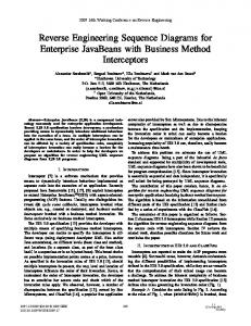
Fig. 5. (a) Long channel device with ALD TiN (111) and (b) short channel device TiN(100); (c) schematics showing TiN with different orientations deposited in trenches of different sizes (c∗ [8]).
Fig. 4. Simulation of Id –Vg curves with considering the effect of multilayer TiN/Ti/TiN (a), and comparison of simulation and silicon data for roll off curves of Vtsat (b), Vtlin (c) (with pocket dose 6e13).
simulation has been calibrated in consideration of different ALD TiN orientations and PVD Ti thickness depending on gate length as discussed above. The measured and simulated Vth roll-off curves for PMOSFETs are shown in Fig. 4(b) and 4(c). As seen, the simulation with calibrated WF fits well with the measurement of real devices. In addition, the RSCE is alleviated compared to the devices with single TiN MG as shown in Fig. 2. The combination of multilayer ALD TiN/PVD Ti/CVD TiN MG can be easily incorporated into modern MOSFETs to effectively improve device performance. The ALD TiN with different orientations for long and short channel devices are shown in Fig. 5 (a) and (b), respectively. In Fig. 5(c), ALD TiN with different orientations deposited in trenches of different sizes, that is, TiN(100) in short trench and TiN(111) in long trench, is schematically shown referring to Yagishita et al. [8]. The WF of TiN(100) is higher than that of TiN(111), demonstrating larger WF of MG for devices with long channel. The TEM images for long channel and short channel devices shown in Fig. 5(a) and Fig. 5(b) agree well with the our assumption illustrated in Fig. 5(c). IV. C ONCLUSION In consideration of different ALD TiN orientations and PVD Ti thickness depending on gate length, the RSCE of PMOSFETs fabricated by gate-last process is effectively suppressed by implementing multilayer ALD TiN/PVD Ti/CVD TiN MG. In short channel devices, the joint efforts of large
WF for TiN(100) and large Vfb for MG with thin PVD Ti mitigate the RSCE. The adopted multilayer ALD TiN/PVD Ti/CVD TiN MG is fully compatible with the state-of-theart complementary metal–oxide–semiconductor (CMOS) technology featuring both high-k and metal gate last integration scheme, which can be used widely to remedy the RSCE for extremely downscaled devices. R EFERENCES [1] B. Yu et al., “Short-channel effect improved by lateral channelengineering in deep-submicronmeter MOSFET’s,” IEEE Trans. Electron Devices, vol. 44, no. 4, pp. 627–634, Apr. 1997. [2] M. Orlowski, C. Mazure, and F. Lau, “Submicron short channel effects due to gate reoxidation induced lateral interstitial diffusion,” in Proc. IEEE Int. Electron Devices Meeting (IEDM), vol. 33. Dec. 1987, pp. 632–635. [3] M. Nishida and H. Onodera, “An anomalous increase of threshold voltages with shortening the channel lengths for deeply boron-implanted N-channel MOSFET’s,” IEEE Trans. Electron Devices, vol. 28, no. 9, pp. 1101–1103, Sep. 1981. [4] T. Hori, “A 0.1-µm CMOS technology with tilt-implanted punchthrough stopper (TIPS),” in Proc. IEEE Int. Electron Devices Meeting (IEDM), Dec. 1994, pp. 75–78. [5] K. Nakajima et al., “Work function controlled metal gate electrode on ultrathin gate insulators,” in Proc. Symp. (VLSI), Jun. 1999, pp. 95–96. [6] I. S. Jeo et al., “A novel methodology on tuning work function of metal gate using stacking bi-metal layers,” in Proc. IEEE Int. Electron Devices Meeting (IEDM), Dec. 2004, pp. 303–306. [7] F. Andrieu et al., “Comparative scalability of PVD and CVD TiN on HfO2 as a metal gate stack for FDSOI cMOSFETs down to 25 nm gate length and width,” in Proc. IEEE Int. Electron Devices Meeting (IEDM), Dec. 2006, pp. 1–4. [8] A. Yagishita et al., “Improvement of threshold voltage deviation in damascene metal gate transistors,” IEEE Trans. Electron Devices, vol. 48, no. 8, pp. 1604–1611, Aug. 2001. [9] J. R. Hauser and K. Ahmed, “Characterization of ultra-thin oxides using electrical C-V and I-V measurement,” in Proc. AIP Conf., Mar. 1998, pp. 235–239. [10] Y. Liu et al., “Investigation of the TiN gate electrode with tunable work function and its application for FinFET fabrication,” IEEE Trans. Nanotechnol., vol. 5, no. 6, pp. 723–730, Nov. 2006.