Model-Based Detection of Rotor Faults Without Rotor ... - IEEE Xplore
Recommend Documents
Keywords: condition monitoring, fault detection, motor current signature analysis (MCSA), squirrel-cage induction motor, virtual instrument (VI). .... The VI created.
Reliable Detection of Induction Motor Rotor Faults. Under the Rotor Axial Air Duct Influence. Chanseung Yang, Student Member, IEEE, Tae-June Kang, Student ...
Mohamed Faouzi Harkat. Electronics Department, Faculty of Science Engineering. University of Annaba, Annaba, Algeria. E.-mail: [email protected].
May 2, 2013 - tween the machine and the electrical grid. The proposed diagnosis approach is based on the use of wavelet analysis improved by a.
(ANN) based technique to identify rotor faults in a three-phase induction motor. The main types of faults considered are broken bar and dynamic eccentricity.
disconnection, to detect broken rotor bars in squirrel-cage induc- tion machines. When the motor is disconnected from the supply no currents flow in the stator ...
AbstractâIn a permanent-magnet (PM) brushless dc motor, the waveform of back electromotive force (emf) is related to the rotor position; hence, the back emf ...
Oct 22, 2007 - Machines Using Complex Wavelet Analysis of Startup Transients. Fernando Briz, Senior Member, IEEE, Michael W. Degner, Senior Member, ...
Keywordsârotor winding; short detection; turbogenerator diagnosis; RSO; flux probe; c-core; voltage pole drop. I. INTRODUCTION. For full and safe operation ...
Abstractâ Electric motors often operate under operating conditions that are constantly changing with time. Most of such applications demand high reliability from ...
the current signals in order to construct feature vectors of each class in the ... and diagnostics can improve reliability, allowing drive repair/replacement to happen ... Automatic condition monitoring and diagnosis are needed to recognize ...
Jun 16, 2016 - grated transmission, the double-rotor electric machine is studied ... machine, hybrid electric vehicles (HEVs), integrated transmission,.
a digital signal processor to study their usefulness for commercial ...... motor current signature analysis using wavelets,â IEEE Trans. Ind. Appl., vol. 40, no. 5, pp.
trical Drives, Automotion and Drives, speedam, pp. B1/13. â B1/18, 2000. [14] C. Kral, F. Pirker, and G. Pascoli, âModel based detection of rotor faults without ...
simplicity and ruggedness of squirrel-cage induction motor make it by far the most commonly used type of electric motor. This is also the reason why they are ...
In this paper some results on detecting broken rotor bars in induction motors are ... Squirrel-cage induction motors are ideal for most industrial applications ...
Unfortunately the electrical machines are not available at all times. Many components of the induction machine are susceptible to failures. For example, the.
The “rotor nl® electric motors” catalogue is to be used as a practical reference
book by both original equipment ..... EN-IEC. ISO. DIN. Nominal operation and
properties. IEC 60034-1. Protection degrees ... As from 1st June 2011 Rotor is
longer ab
identified through dedicated bending and torsion static tests. Typically .... considering unsymmetrical bending conditions. ..... [10] R22 Maintenance Manual.
Department of Automotive Engineering, Hanyang University, Seoul, Korea. Motor R&D Center, S&T Daewoo Co., Ltd., Busan, Korea. In this paper, the bridge ...
Estimation of Rotor Resistance of an Induction. Motor Using Extended Kalman Filter and Spiral. Vector Theory. Mohamed Menaa, Omar Touhami and Rachid ...
Abstract â Multi-mesh geared systems are common in many applications including rotorcraft and automotive transmissions. Coupling mechanism occurred due ...
high-speed cruise capabilities of a conventional airplane with the hovering capabilities of a helicopter by tilting their four rotors. Changing the flight condition ...
Fernando Briz, Member, IEEE, Michael W. Degner, Senior Member, IEEE, Pablo ... F. Briz, P. GarcÃa, and J. M. Guerrero are with the Department of Electrical,.
Model-Based Detection of Rotor Faults Without Rotor ... - IEEE Xplore
technique to detect rotor asymmetries in the squirrel cage of an induction ... rotor fault detec- tion technique without rotor position sensor can be realized.
784
IEEE TRANSACTIONS ON INDUSTRY APPLICATIONS, VOL. 41, NO. 3, MAY/JUNE 2005
Model-Based Detection of Rotor Faults Without Rotor Position Sensor—The Sensorless Vienna Monitoring Method Christian Kral, Member, IEEE, Franz Pirker, Member, IEEE, and Gert Pascoli, Member, IEEE
Abstract—This paper deals with an extended approach of the Vienna Monitoring Method (VMM), which is a model-based technique to detect rotor asymmetries in the squirrel cage of an induction machine. The conventional VMM requires the measured voltages, currents, and the signal of a rotor position sensor. The novel scheme presented in this paper alternatively works without a rotor position sensor. In particular, for low-inertia drives, accurate estimation of rotor position is required. The rotor-fault-related double-slip-frequency torque modulation causes a speed ripple with the same frequency. Consequently, low-inertia drives are exposed to higher speed ripples. In this case, it is not sufficient to estimate the mean value of the actual speed, only. Even the speed ripple has to be acquired to benefit from the accuracy of the employed models of the VMM. The proposed technique evaluates the signatures of an inherent rotor fault in order to determine the rotor position signal. The speed ripple can be obtained from the torque modulations that the models already compute. This way, an accurate rotor fault detection technique without rotor position sensor can be realized. Index Terms—Diagnostics, electrical rotor asymmetry, fault detection, induction machine, model, monitoring, rotor fault, squirrel cage, torque, without speed sensor.
I. INTRODUCTION
E
LECTRICAL rotor asymmetries such as broken rotor bars and end rings give rise to fault-specific signatures in the current, power, torque, and speed of an induction machine. There arise two characteristic harmonics next to the fundamental of the current spectrum. Their respective frequency distance from the fundamental is twice the slip frequency. Consequently, they are called the lower and the upper sideband harmonics of the current. The low-frequency power, torque, and speed harmonics, however, emerge at twice the slip frequency. Many fault detection schemes evaluate the fault-specific lower and upper sideband harmonics of the current [1]–[4]. They are, therefore, called motor current signature analysis (MCSA). The advantage of these techniques is, that only one line current has to be measured. On the other hand, the assessment of the magnitudes of both the lower and upper sideband
Paper IPCSD-05-011, presented at the 2003 IEEE International Symposium on Diagnostics for Electrical Machines, Power Electronics and Drives, Stone Mountain, GA, August 24–26, and approved for publication in the IEEE TRANSACTIONS ON INDUSTRY APPLICATIONS by the Electric Machines Committee of the IEEE Industry Applications Society. Manuscript submitted for review March 29, 2004 and released for publication March 7, 2005. The authors are with Arsenal Research, 1030 Vienna, Austria (e-mail: [email protected]; [email protected]; gert.pascoli@arsenal. ac.at). Digital Object Identifier 10.1109/TIA.2005.847316
current is disadvantageous. In general, the assessment of the magnitudes is a challenging task, because the amplitudes of these harmonics are highly dependent on the operating conditions such as load torque, machine supply, and inertia. For induction machines with high inertia, a formula for the estimation of the number of broken bars is stated in [5]. However, MCSA usually assumes steady-state operation, since a Fourier analysis of the current has to be performed. Time-varying loads complicate motor current signature analysis and require sophisticated evaluation techniques [6], [7]. Other detection techniques evaluate the double-slip-frequency harmonics of the power spectrum [8]–[10] and are, therefore, called power signature analysis (PSA). These techniques have to acquire currents and voltages. The drawback of additional measuring equipment is compensated by the fact that the magnitude of only one spectral component—at twice the slip frequency—has to be assessed. Furthermore, power reflects the actual machine condition better than a single motor current. The Vienna Monitoring Method (VMM) is a model-based technique which evaluates the calculated torque of two machine models with different model structure [11], [12]. In the case of a rotor fault, double-slip-frequency torque modulations arise in the modeled torques. The VMM senses the difference of the torque fluctuations to diagnose a rotor fault. The employed mathematical models evaluate the voltage and the current space phasor as well as the measured rotor position. It has been shown, that the fault indicator delivered by the VMM is independent of load torque [13], inertia [14] and machine supply [15]. Furthermore, it turned out that the sensitive VMM allows the detection of small rotor faults such as voids and cracked rotor bar [16]. Accurate rotor position acquisition is the key to the high accuracy and sensitivity of the VMM. The required rotor position measurement is, however, highly disadvantageous and undesirable. Consequently, it has been an endeavor ever since to eliminate the position sensor. The succeeding rotor speed and rotor position estimation technique is presented in this paper. Some limitations with respect to the accuracy of the sensorless VMM, however, have to be accepted.
II. VMM The VMM uses two mathematical machine models in order to detect and assess electric rotor asymmetries. The structural scheme is depicted in Fig. 1.
KRAL et al.: MODEL-BASED DETECTION OF ROTOR FAULTS WITHOUT ROTOR POSITION SENSOR
Fig. 1. Scheme of the Vienna Monitoring Method.
The voltage model (superscript ) utilizes both the measured voltage space phasor and the current space phasor in order to determine the stator flux phasor . (1) The required parameter of the voltage model is the stator resistance . The current model is evaluated in the rotor fixed reference is required to frame. Therefore, the actual rotor position transform the stator current space phasor into the rotor fixed frame. The determined rotor flux phasor , therefore, also refers to the rotor fixed frame (2) The parameters of the current model are the rotor (magnetizing) reactance and the rotor time constant . The respective instantaneous torque computed by each of the models is computed by means of the flux space phasors and the conjugate current phasor in the respective reference frame
785
model-specific components are different. Both the voltage and the current model are based on symmetric machine models. Fault-specific harmonics of voltages and currents are caused by internal rotor asymmetries of the real induction machine and, therefore, give rise to a different response of the symmetrical machine models. For example, an induction machine with infinite inertia is controlled by a torque controller (no speed control). Steady-state conditions are assumed. The controller is based on a current model and does not sense any speed ripple due to the infinite inertia [15]. The controller injects sinusoidal currents according to the commanded torque. In such a case, an electrical rotor asymmetry gives rise to sideband harmonics of the voltages, because currents are controlled sinusoidally. Therefore, the current model computes constant torque (the commanded torque) whereas the voltage model senses the real torque modulations since the voltage model evaluates currents and voltages. It has been shown that the amplitude and the phase shift of the relative torque difference are independent of load [13], inertia [14], and machine supply [15], whereas the individual torque components show all these dependencies. Therefore, the magnitude of the relative torque modulation is only proportional to the extent of the rotor asymmetry. The absolute value of the magnitude of the relative torque modulation, however, may vary with the actual motor design [17]. The main advantages of the VMM over the MCSA and the PSA is that the derived fault indicator is independent of load (during steady-state and transient load operation), supply (open-loop and controlled closed-loop inverter and mains) and inertia. However, the relative torque difference is evaluated by means of a spatial data clustering technique which allows a reliable and robust determination of the magnitude of the double-slipfrequency component independent of the actual slip frequency. This means that the relative torque difference (5) is evaluated versus a spatial angle . The spatial angle is the phase angle of the rotor flux space phasor with respect to the rotor fixed reference frame
(3) (4) Preceding investigations showed that the relative torque difference (5) can be used to clearly determine electric rotor asymmetries [16]. This term equals the difference of the torque of the voltage and the torque of the current model, subsequently divided by the estimated average value of load torque. The average load torque can be determined from the torque of the voltage model by means of a low-pass filter. In the case of an ideal symmetric induction machine both models compute the same torque. This causes the torque difference to vanish. In contrast, an electrical rotor asymmetry excites a double-slip-frequency torque component in both models. Due to the different model structure and different input quantities, phase angle and magnitude of the voltage and current
(6) This angle represents the location of the rotor flux with respect to the electrical rotor circumference. Therefore, the double-slipfrequency modulation of the relative torque difference in the time domain is mapped to a second harmonic oscillation in the spatial domain with respect to as shown in Fig. 2. The spatial range of values of becomes subdivided into equidistant segments. The data value associated with each (discrete) cluster is the averaged instantaneous relative torque difference that the angle matches the actual discrete cluster segment. This algorithm is applied for an evaluation time of several seconds. Once the flux phasor accomplished several revolutions, a representative discrete pattern of the waveform of the torque difference is obtained. These discrete data represent the double-slip-frequency modulation of the relative torque difference in the spatial domain. The averaged cluster values are then subject to a discrete Fourier analysis. The magnitude of the second harmonic serves as fault indicator.
786
IEEE TRANSACTIONS ON INDUSTRY APPLICATIONS, VOL. 41, NO. 3, MAY/JUNE 2005
current or power spectrum. These schemes have also been investigated. They do not, however, provide the required accuracy, because the estimated and the actual rotor position signal are not supposed to become asynchronous. B. Implementation
Fig. 2. Spatial data clustering technique. (a) Relative torque difference versus the evaluation angle . (b) Relative torque difference becomes mapped into spatial data clusters.
III. ROTOR POSITION ESTIMATION A. Requirements The rotor position is required for the transformation of the current space phasor into the rotor fixed reference frame. Furthermore, the subsequently computed rotor flux phasor is used to determine the torque of the current model and the evaluation angle (6). Therefore, the rotor position signal has to be very accurate. It is important that the deviation of the estimated rotor position from the actual rotor position is not too large during the evaluation period. The realization of such an accuracy is a challenging task. The contributions of the torque components of both the voltage and current model (5) are highly dependent on inertia [14]. Nevertheless, the amplitude of the relative torque difference is independent of inertia. Drives with very high inertia cause the relative torque difference to be dominated by the torque modulation of the voltage model. In the case of low-inertia drives it is mainly the current model which contributes to the relative torque difference. Therefore, accurate rotor position estimation is more crucial in the latter case. Rotor faults cause a double-slip-frequency torque modulation. Torque modulations of low-inertia drives give rise to a relatively large speed ripple (compared with a high-inertia drive). This speed ripple is also present in the rotor position. If the rotor position estimation does not take this speed ripple into account accurately, the torque modulation computed by the current model may be incorrect. The rotor position estimation technique proposed in this paper meets these requirements. It is capable to determine the actual speed and rotor position from the fault specific signal which emerges in the calculated torque. Therefore, an incipient rotor failure has to be large enough to cause a sufficient speed indicating signal that can be processed. If the fault-specific signal is too low, the algorithm for the rotor fault detection will be disabled. Only a sufficient fault severity, such as a single broken rotor bar, will therefore allow a reliable fault detection. For low-inertia drives it also has to be assumed that the total inertia of the drive is constant and a known quantity. Otherwise the speed ripple cannot be derived from the computed torque modulations. For high-inertia drives the determination of the ripple in the rotor position signal is not that crucial. Other conceivable speed detection techniques may evaluate rotor slot harmonics or the eccentricity related harmonics in the
The scheme of the employed rotor speed estimation is shown in Fig. 3. An incipient rotor failure causes a pulsation of the electromagnetic torque and shaft torque with twice the slip frequency. The voltage model computes the actual electromagnetic torque. Therefore, the actual electromagnetic torque modulations are faithfully reflected in the modeled torque (3) of the voltage model . In order to determine rotor speed from the torque harmonics of the induction machine, supply frequency has to be determined. This quantity is derived by differentiation of the phase angle of the voltage space phasor . First of all, torque and voltage phasor have to be downsampled. This is required to stabilize the used low pass filters which have a very low cutoff frequency in the order of a few hertz. The downsampled torque is subject to a filter 1 which eliminates everything but the double-slip-frequency component (Fig. 3). Filter 1 consists of a low-pass filter (F) that has a cutoff frequency slightly above twice the rated slip frequency. An additional filter (DC) has an even lower cutoff frequency in order to determine only the dc component of the input signal. The double-slip-frequency component of the electromagnetic results therefore from the difference of the outputs torque of filter (F) and filter (DC). Filter 1 causes the large lag, which is corrected by 2 . The frequency-dependent lag of filter 1 is actually caused by filter (F). Therefore, an additionally series-connected filter (F) causes twice the lag. The difference between the phase angle of the twice filtered and the single filtered electromagnetic torque is . actually used to compensate the frequency dependent lag However, due to the applied Hilbert transformation, we finally . The real part of this quantity is receive a torque signal in phase with the solely double-slip-frequency modulations of the electromagnetic torque . These torque pulsations are interacting with speed, whereas the (constant) load and the average value of the electromagnetic torque do not contribute to the derivative of speed (7) In this equation is the per-unit total inertia of the motor and the load. Since we utilize the complex quantity , which is solely consisting of a double-slip-frequency pulsation, we can write (7) without applying a numeric differentiation as
(8) In this equation, mechanical speed is composed of the avand a double-slip-frequency component erage value caused by the double-slip torque modulation due to the principle of angular momentum. The average value is the difference between stator and rotor frequency, determined in 3 and 4 .
KRAL et al.: MODEL-BASED DETECTION OF ROTOR FAULTS WITHOUT ROTOR POSITION SENSOR
787
Fig. 3. Scheme of the sensorless rotor speed estimation. (A): determines angle of a complex quantity; (C): controller; (D): derivative unit; (DC): dc (ultra low pass) filter; (DS): downsample; (F): low-pass filter; (H): Hilbert transform; (US): upsample; t : torque calculated by the voltage model; v : stator voltage space phasor; and : p.u. inertia.
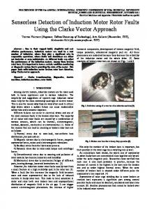
Fig. 4. Measurement result of a 10-kW four-pole induction machine with one broken rotor bar and low inertia at full load. (a) Torque modulation of the voltage model, the current model, and the relative torque difference, evaluated with position encoider. (b) Torque modulation of the voltage model, the current model, and the relative torque difference, evaluated without position. (c) Difference of the measured and estimated rotor position.
The speed modulation is derived according to (8). Finally, rotor is determine by computing the derivative of meposition chanical rotor speed . IV. MEASURED RESULTS Measured results have been obtained for a low-, a medium-, and a high-inertia dc generator clutched to a 10-kW four-pole squirrel-cage induction motor with one completely broken rotor bar. Figs. 4(c), 5(c), and 6(c) show the deviation of the estimated rotor angle from the measured rotor angle for the three different cases of inertia. The result is quite satisfactory and fulfills the demanded accuracy. The determined deviation of the estimated
and the measured rotor angle is within a range of 20 with respect to an observation time of 10 s. Figs. 4–6 show the torque modulations computed by the voltage and the current model and the relative torque difference as function of the evaluation angle (6). It can be seen that the torque signals mainly consist of a second harmonic. Figs. 4(a), 5(a), and 6(a) represent the torque modulations of a conventional VMM with rotor position sensor. The results of the sensorless scheme considering the actual inertia are represented in Figs. 4(b), 5(b), and 6(b). The amplitude of the second harmonic of the relative torque difference serves as fault indicator for the VMM. The numerically obtained values of the fault indicators evaluated by the conventional VMM with rotor position sensor are summarized in
788
IEEE TRANSACTIONS ON INDUSTRY APPLICATIONS, VOL. 41, NO. 3, MAY/JUNE 2005
Fig. 5. Measurement result of a 10 kW four pole induction machine with one broken rotor bar and medium inertia at full load; (a) torque modulation of the voltage model, the current model and the relative torque difference, evaluated with position encoider, (b) torque modulation of the voltage model, the current model and the relative torque difference, evaluated without position, (c) difference of the measured and estimated rotor position.
Fig. 6. Measurement result of a 10-kW four-pole induction machine with one broken rotor bar and high inertia at full load. (a) Torque modulation of the voltage model, the current model, and the relative torque difference, evaluated with position encoider. (b) Torque modulation of the voltage model, the current model, and the relative torque difference, evaluated without position. (c) Difference of the measured and estimated rotor position. TABLE I MEASURED FAULT INDICATORS OF THE VIENNA MONITORING METHOD
can yet be detected by the conventional VMM which uses a position encoder. Measuring and simulation results of the fault indicator of the conventional VMM as function of a single rotor bar resistance increase are presented in [16]. V. CONCLUSION
Table I (rows conventional). This table also shows the obtained fault indicators for the sensorless scheme considering the actual inertia (rows sensorless) and infinite inertia (rows sensorless, no speed ripple). The deviation of the fault indicator of the sensorless method from the conventional one is less than 6% which is a satisfactory result. The scheme with infinite inertia works quite well for the medium- and high-inertia drives. It fails, however, for the low-inertia drives. Position estimation is in conjunction with an inherent error. Measuring results showed that low rotor asymmetries, such as partly cracked rotor bars or shrink holes, do not give rise to a sufficient magnitude of the modeled torque harmonic in order to track the rotor position signal. Such low rotor asymmetries
The conventional VMM processes measured voltages, currents, and a rotor position signal. An alternative technique has been proposed in this paper. It extracts the rotor position signal from the torque modulations of the voltage model without the need of a position or speed sensor. This sensorless fault detection scheme of the VMM can be applied, if a sufficient torque modulation can be tracked and evaluated. Only a sufficient fault severity will, therefore, allow a reliable fault detection. For low inertia drives it is required to know the total inertia of the motor and the load. A limitation of the VMM is that some machine parameters have to be determined in order to operate the employed models. Stator resistance is usually measured. Rotor reactance and rotor time constant may either be measured or determined by means of a parameter tracking scheme that computes the actual rotor parameters on line. The deviation of the estimated rotor position of the proposed sensorless VMM from the measured rotor position is about 20 within 10 s. This circumstance gives rise to a reduced accuracy
KRAL et al.: MODEL-BASED DETECTION OF ROTOR FAULTS WITHOUT ROTOR POSITION SENSOR
of the proposed technique with respect to the assessment of the severity of the rotor fault. In particular, low rotor asymmetries such as partly cracked rotor bars cannot be detected with the sensorless VMM, since the modeled torque oscillations are too small in order to derive a sufficient rotor position signal. Measured results have been presented for a conventional scheme with a position sensor and the proposed sensorless technique. The investigated induction machine had one completely cracked rotor bar. The fault indicator determined by the novel scheme deviates from the reference value by approximately 6%, which is a satisfactory result. It also has been shown that the total inertia is not required for medium- and high-inertia drives. REFERENCES [1] R. Schoen and T. Habetler, “Evaluation and implementation of a system to eliminate arbitrary load effects in current-based monitoring of induction machines,” in Conf. Rec. IEEE-IAS Annu. Meeting, 1996, pp. 671–678. [2] S. Nandi, R. Bharadwaj, H. Toliyat, and A. Parlos, “Study of three phase induction motors with incipient rotor cage faults under different supply conditions,” in Conf. Rec. IEEE-IAS Annu. Meeting, vol. 3, 1999, pp. 1922–1928. [3] W. Thomson and M. Fenger, “Current signature analysis to detect induction motor faults,” IEEE Ind. Appl. Mag., vol. 7, no. 1, pp. 26–34, Jan./Feb. 2001. [4] A. Bellini, F. Fillipetti, G. Franceschini, C. Tassoni, R. Passaglia, M. Saottini, and G. Tontini, “ENEL’s experience with on-line diagnosis of large induction motors cage failures,” in Conf. Rec. IEEE-IAS Annu. Meeting, vol. 1, 2000, pp. 491–498. [5] R. Hirvonen, “On-line condition monitoring of defects in squirrel cage motors,” in Proc. ICEM’94, 1994, pp. 267–272. [6] R. Schoen and T. Habetler, “Effects of time-varying load on rotor fault detection in induction machines,” in Conf. Rec. IEEE-IAS Annu. Meeting, 1993, pp. 324–330. [7] G. Salles, F. Filippetti, C. Tassoni, G. Crellet, and G. Franceschini, “Monitoring of induction motor load by neural network techniques,” IEEE Trans. Power Electron., vol. 15, no. 4, pp. 762–768, Jul. 2000. [8] S. Legowski, A. S. Ula, and A. Trzynadlowski, “Instantaneous power as a medium for the signature analysis of induction motors,” IEEE Trans. Ind. Appl., vol. 32, no. 4, pp. 904–909, May/Jun. 1996. [9] S. Cruz and A. Cardoso, “Rotor cage fault diagnosis in three-phase induction motors by the total instantaneous power spectral analysis,” in Conf. Rec. IEEE-IAS Annu. Meeting, vol. 3, 1999, pp. 1929–1934. [10] A. Trzynadlowski and E. Ritchie, “Comparative investigation of diagnostic media for induction motors: A case of rotor cage faults,” IEEE Trans. Ind. Electron., vol. 47, no. 5, pp. 1092–1099, Oct. 2000. [11] R. Wieser, C. Kral, F. Pirker, and M. Schagginger, “On-line rotor cage monitoring of inverter fed induction machines, experimental results,” in Proc. SDEMPED’97, 1997, pp. 15–22. [12] , “High sensitive rotor cage monitoring during dynamic load operation the Vienna monitoring method,” in Proc. ICEM’98, 1998, pp. 432–437. [13] C. Kral, F. Pirker, and G. Pascoli, “Influence of load torque on rotor asymmetry effects in squirrel cage induction machines including detection by means of the Vienna Monitoring Method,” in Proc. EPE’01, 2001, CD-ROM. [14] , “Influence of inertia on general effects of faulty rotor bars and the Vienna monitoring method,” in Proc. SDEMPED’01, 2001, pp. 447–452.
789
[15] R. Wieser, C. Kral, F. Pirker, and M. Schagginger, “The Vienna induction machine monitoring method; on the impact of the field oriented control structure on real operational behavior of a faulty machine,” in Proc. IEEE IECON’98, 1998, pp. 1544–1549. [16] C. Kral, F. Pirker, G. Pascoli, and H. Oberguggenberger, “On the sensitivity of induction machine rotor cage monitoring—The Vienna monitoring method,” in Proc. Symp. Power Electronics, Electrical Drives, Automotion, and Drives, 2000, pp. B1/13–B1/18. , “Influence of rotor cage design on rotor fault detection by means [17] of the vienna monitoring method,” in Proc. ICEM’02, 2002, CD-ROM.
Christian Kral (M’00) received the Dipl.-Ing. and Ph.D. degrees from Vienna University of Technology, Vienna, Austria, in 1997 and 1999, respectively. From 1997 to 2000, he was a Scientific Assistant at the Institute of Electrical Drives and Machines, Vienna University of Technology. Since 2001, he has been with Arsenal Research (Österreichisches Forschungs- und Prüfzentrum Arsenal Ges.m.b.H.), Vienna, Austria. From January 2002 until April 2003 he was on sabbatical as a Visiting Professor at the Georgia Institute of Technology, Atlanta. His research activities are focused on diagnostics and monitoring techniques, machine models, and the simulation of faulty machine behavior.
Franz Pirker (M’03) was born in 1968. He received the Dipl.-Ing. degree in electrical engineering from Vienna University of Technology, Vienna, Austria, in 1997. Since 1999, he has been the Head of Monitoring, Energy, and Drive Technologies at Arsenal Research (Österreichisches Forschungs- und Prüfzentrum Arsenal Ges.m.b.H.), Vienna, Austria. In this area, the main research topics are online monitoring of machines and online diagnoses of high-voltage generators. In these fields, Arsenal Research is developing new online monitoring methods and products. His main research interests are inverter drives, in particular, in combination with faulty induction machines. As a member of the Rotor Fault Detection Group, he worked on the realization of an online monitoring system in an industrial voltage-source inverter drive.
Gert Pascoli (M’03) received the Dipl.-Ing. degree from Vienna University of Technology, Vienna Austria, in 1995. In 1991, he joined the Institute of Switchgear and High Voltage Technology, Vienna University of Technology. Since 1996, he has been with Arsenal Research (Österreichisches Forschungs- und Prüfzentrum Arsenal Ges.m.b.H.), Vienna, Austria. His main research topics are the online monitoring of machines and the partial discharge diagnosis of electrical insulations of high- and low-voltage machines.