2006-01-0862
Model Based Embedded System Development for In-Vehicle Network Systems Joonwoo Son Daegu Gyeongbuk Institute of Science & Technology – Department of Mechatronics
Ivan Wilson DsysD Ltd.
Wootaik Lee Changwon National Univ. – Department of Mechatronics
Suk Lee Pusan National Univ. – School of Mechanical Engineering Copyright © 2006 SAE International
ABSTRACT This paper aims for a seamless development process for automotive body network system development with model-based approach. It also describes a generic software architecture that provides clear-boundaries between the software components and that can also act as a guide for each development phase. The CASE tool Statemate is used for feature behavioral modeling and verification. NodeAllocator builds the ECU models by mapping the behavioral model and physical network architecture. The virtual prototypes and the basic bus communication information are created and validated using software in loop simulation. The validated functional models are refined for implementation models and MicroC is used for application task code, OS design and software integration.
(Computer Aided Software Engineering) tools support MBDP to easily adopted, but the CASE tools can’t cover all the process. Therefore, most of MBDP researches contain their own effort to fill up the gaps between CASE tools [1][4][5][6][7][8]. Another challenge in MBDP is the efficient integration of software components such as auto-generated code, legacy code and the other commercial software components. This paper aims for a seamless development process for automotive body network systems with structured methods fully supported by CASE tools, Statemate/MicroC. It also describes a generic software architecture which is devised to achieve the technical goals of modularity, scalability, transferability and reusability of functions [9]. A case study on automotive network system for window lift feature was demonstrated.
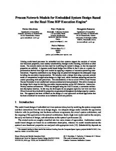
INTRODUCTION The automotive embedded system becomes even more complex and occupies more portion of vehicle price lately [1]. In order to design products which achieve an improved functionality and reliability keeping the costs and complexity of the system limited, automotive industries apply a system approach for the body network system development [2]. Furthermore, short time-tomarket cycles and a considerable number of variants require a well-structured development process such as Model Based Development Process (MBDP) and generic software architecture supporting the reuse of components at all phases. The MBDP follows the widely accepted conventional software development V-process to facilitate the understanding and early validation of the requirements [3]. Figure 1 shows a typical V-process for model based development process. Some CASE
Figure 1. V Process for Model-Based Development
MODEL BASED DEVELOPMENT PROCESS FOR IN-VEHICLE NETWORK SYSTEM MBDP attempts to improve quality and reduce cycle time by using modeling and its ability to simulate to introduce early validation of requirements. The V-process is a process which provides continuous focus on the requirements of a customer by documenting requirements at the start of development, designing according to those requirements, implementing those requirements, and finally validating based on the input customer requirements. In order to achieve a successful integration of model based processes, the definition of the various process steps is essential. Usually, model based development process consists of following major steps [1][3]: • • • • • •
Requirements Capturing and Analysis Functional High Level Modeling Architecture Design and Partitioning Implementation Modeling Auto-Code Generation and Model Optimization Software Integration and Build
REQUIREMENT CAPTURING AND ANALYSIS The success of any product development is dependent on the creation of clear, complete, and un-ambiguous requirements [3]. Incomplete requirements lead to the implementation engineers filling the gaps to the best of their ability. Not too much of a problem when it is a complete system, but in a distributed system this is a big problem as other engineers have to rely on information coming from all over the system. Ambiguous requirements tend to mean that the delivered system does not exactly do what was originally intended. Poorly understood requirements are usually due to a lack of knowledge of the system; this will always result in a bad design. Therefore, the requirement capturing and analysis phase must be formalized. These requirements should be testable, traceable, and able to be implemented. FUNCTIONAL HIGH LEVEL MODELING According to requirement capturing document, functional models should be created. But the vehicle electronic system is too large to be address in one goes, so break it down according to function groups. For example, power seat control, window control, heating and ventilation, exterior lighting control and so on. Once the main sub-systems have been identified, ensure that the information flowing into and out of them is clearly defined. Perhaps a particular sub-system will be delivered from a supplier, and as such it will need to be a well-bounded system for them to work with. Next break these sub-systems down further into features that the sub-systems will have to deliver. Top-down design approach is suitable for this process. While building the functional model, Statemate simulation feature provides
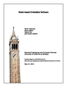
testing and validating capabilities. A virtual prototype can be created to communicate with customer or the other project members. These features enable us to test and validate the software functionality without hardware in early stage. Using the virtual prototype, test plan should be specified in detail and the specified plan will be used an actual prototype and product validation as well. ARCHITECTURE DESIGN AND PARTITIONING When the behavioral model is released, two kind of works are started, one for network system development and the other for ECU (Electronic Control Unit) software development. In this subsection, the work for network system development will be described. Considering the amount of data and functionality that the embedded systems contain and the exponential increase in complexity, the partitioning process can often be error prone, time consuming and labor-intensive. In this project, NodeAllocator, the add-on tool for Statemate, was used to allow quick and easy functional trade off analysis to try different allocations of functional logic blocks to physical nodes to determine a realistic and cost effective solution to the system architecture. Network Architecture Design and Partitioning The NodeAllocator allows system designers to create network architectures comprising of ECUs connected by networks. The functionality, as designed in Statemate, is allocated to the ECUs by the architecture designer. The NodeAllocator calculates the network traffic, static busload and gives system completeness feedback to ensure all signals have a source and a sink. ECU models are then created by the NodeAllocator in Statemate ready for implementation. NodeAllocator also provides us with the basic CAN database file including ECU node and exchanged signal information. The system engineer can group the signals into some message to optimize the network performance. The created CANdb file will be used for two purpose; one for network simulation and the other for auto-code generation of network embedded software. Vector’s CAN database acts as a standard format of automotive CAN and LIN network information. This database file contains the information about Rx/Tx nodes, messages, signals and transmission strategy and so on. Figure 2 shows partitioning process and CAN database usages for network system design. Network Simulation Environment Development Before the time, effort and expense of building a prototype is taken, the model should be tested as a unit with other models from the system. This ensures system integration as early as possible in the design. The distributed system simulation is achieved by linking Statemate with CANoe, enabling an ECU model to interact with a system under the real-time constraints of a live network. This is used initially to dynamically test the entire network architecture design and later on to enable parallel ECU development. In order to simulate
the network model on CANoe environment, proper CAN database must be created by grouping the signals into the messages and adding some information. IMPLEMENTATION MODELING Once the system design and ECU designs have been validated on the virtual car, the designs should be moved to the implementation phase. To generate code for embedded applications, all the software design, implementation details and constraints has to be imposed into the model such that the generated code can satisfy all the requirements.
Physical Model
Functional Model
AUTO-CODE GENERATION AND MODEL OPTIMIZATION The auto-code generation includes code generation, model optimization and validation. The model optimization process is to replace the less efficient modeling representation with the equivalent representation that can yield the most efficient code. SOFTWARE INTEGRATION AND BUILD The software integration links all source code including generated application code, I/O device drivers, communication kernel and operating system code. Generic software architecture helps the software integration of application behavior, hardware drivers and commercial software components. The generic software architecture will be described in the next section.
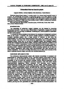
GENERIC SOFTWARE ARCHITECTURE To achieve the technical goals of modularity, scalability, transferability and reusability of functions, while also affording a high degree of early testability, a Generic Software Architecture was deemed necessary. In this project, AUTOSAR layered approach was mimicked to obtain the advantages [9][10]. SOFTWARE ARCHITECTURE OVERVIEW A layered architecture, Figure 3, was devised so that all software components are isolated from one another by the middleware. Once the middleware API was specified it allowed the components, including the application, to be developed separately. Drag & Drop OS AND MIDDLEWARE DESIGN
Network Simulation
Embedded Kernel
The Generic Architecture was devised to be fully ANSI C code compliant and OS independent. The tasks were serviced by a simple scheduler running in an infinite single main loop. MicroC has the ability to generate code using templates which can be highly customized using a built in tool. In this case they were tailored to a scheduler with 3 attributes to define the cycle time, starting time and task name, in order to assign the execution time slot for each task.
Application Designed in Statemate and Implemented in Rhapsody MicroC
BootLoader
Middleware
IO Device Driver Figure 2. Partitioning Process and CAN Database Usage
Bus Kernels CAN CAN&&LIN
Node Management
Diagnostic Kernel
EEPROM Driver
Figure 3. Generic Software Architecture
The middleware isolates the software components from one another. All data is transferred via the middleware which can offer data buffers, call-backs, data conversion and remote procedure calls. LOWER LAYER DESIGN At the beginning of model based software development, clear cut boundaries between models and lower layer drivers must be defined. Questions as to who debounces data, converts the signals to engineering units and manages I/O failure detection must be answered. In this case it was decided that the application should only receive good data in engineering units. I/O Device Drivers I/O drivers provide functions with simple input and output values or the result of an algorithm. They are either called directly from the middleware when the data is requested by the application or they are serviced from an I/O Driver task that periodically polls the hardware and writes the data to the middleware. EEPROM Drivers This manages non-volatile memory storage and recall. EEPROM writing can be time consuming and consequently must be done outside the normal application execution loop to ensure real-time performance. Bus Kernels for CAN and LIN The CAN/LIN kernel usually consists of smaller layers based on OSEK-COM/NM. To ensure compatibility and high quality, most of OEMs require suppliers use commercial software components such as Vector CANbedded. Diagnostic Kernel Diagnostic data is usually accessed via CAN bus. The software architecture was designed to take advantage of Vector CANbedded components, the CAN/LIN kernel and the Diagnostics kernel. Boot Loader The Boot loader is an embedded software component that establishes a connection between the development or serial control unit as well as a main computer and supports the downloading of application software onto the control unit via the CAN or LIN buses. Node Management The Node Management Layer is used by the node to control the start up, shut down, and error handling for a node where these functions do not involve interaction
with other nodes of the network and can be managed locally.
CASE STUDY – WINDOW LIFT CONTROL This case study is based on an actual OEM project for an automotive body network system development. This paper describes the window lift control feature of body network system. The following functionality has to be considered: • • • •
Manual / Automatic control of all 4 windows Child protection Primitive shut protection Restriction / extension of the functionality depending on the status of other components (ignition, door position, etc.)
REQUIREMENTS CAPTURING AND ANALYSIS According to the key steps of MBDP, the requirement capturing documents which describe functional behavior and test scenarios should be created. The requirements documentation includes the following aspects: • • •
Description of the customer use scenarios Context diagram describing all inputs and outputs A set of unwanted scenarios
FUNCTIONAL HIGH LEVEL MODELING The functional high level model was built and validated using Statemate simulation feature. Top level activity chart, which acts as context diagram to show input, output signal and tasks, was created after task decomposition. Figure 4 illustrates the top level activity chart. A virtual prototype was created to communicate with customer and project members. The virtual prototype helps to specify test plan in detail and the test plan is used for an actual prototype and product validation as well. ARCHITECTURE DESIGN AND PARTITIONING Network system development starts with physical architecture. Physical architecture can be created by analyzing the distribution of sensors and actuators, and then selecting the optimal location and number of nodes. Figure 5 shows the physical architecture of the windows lift system. The windows lift system consists of CAN network for front doors and LIN network for rear doors. BCM (Body Control Module) has the role of gateway between CAN and LIN buses. NodeAllocator builds the ECU models by mapping the functional model to physical model. Network Simulation Environment Development The ECU models are used for SILS (Software-In-theLoop Simulation) by linking CANoe network simulation
models. NodeAllocator also provide us with basic CANdb information. The network traffic and static busload information which calculated by the NodeAllocator was used to design optimal message grouping. CANoe SILS environment can help to verify and examine the network system performance.
IMPLEMENTATION MODELING In order to generate code for embedded applications from the released functional model, all the software design, implementation details and constraints were imposed into the model such that the generated code can satisfy all the requirements.
Embedded Network Software Design In the automotive embedded software development, communication network design is one of the most complex and important parts lately. The most of automotive OEM’s want to use a commercial software component for their own network protocol by network software experts such as Vector Cantech and Volcano Automotive. In this project, Vector’s CANbedded software is used for CAN communication kernel. This tool generates the source codes for CAN communication based on CAN database. The generated codes are integrated through the middleware, the functions that transfer Rx/Tx signals to the application are mapped each data items on MicroC.
AUTO-CODE GENERATION AND MODEL OPTIMIZATION During auto code generation work, model optimization was conducted to get more efficient application code. I/O DEVICE DRIVERS DESIGN In this project, the lowest level of hardware I/O device driver software was generated by micro-controller configuration tool, Processor Expert. The key of the I/O device driver design is to provide access to all hardware resource via generic APIs. This design enables the application software to be independent of the underlying hardware platform. Thus, it makes the application software portable. In order to communicate between I/O data and application code via the middleware in the generic software architecture, some codes are added by hand according to the generic software architecture. SOFTWARE INTEGRATION AND BUILD
Figure 4. Functional Top Chart for Windows Lift System
Software integration work started with implementation model, I/O driver software, CAN/LIN communication kernel, diagnostic kernel, boot loader, and node management code. Each software unit must be tested to check the integrity of the functional behavior of the generated code. The software integration work continues the model based theme of early validation by using the simulation environment of the implementation model to revalidate the software model to the original input requirements. The performance requirements and constraints such as response time must be tested and the result feedback to the implementation model and software codes. For some critical sections, if the code efficiency can’t be achieved by the automatically generated code, the hand written code can be used to replace model function blocks. The generic software architecture, which defines the boundary of each component and interface specifications and static scheduler for the tasks, can reduce the integration effort and errors. Thus, the reliability of designs are improved through the use of a layered software platform that allows for the easy integration of generate software.
CONCLUSION
Figure 5. Physical Architecture of Windows Lift System
Model based development processes, which follow the widely accepted conventional software development Vmodel, are becoming more and more popular in the automotive industry. The objective of model based software development is the creation of reusable, reliable software components that are consistently validated against the input requirements. This paper
focuses on a case study on automotive body network system development using model-based approach and the ideal interactive tool chains for the rapid introduction of the model-based process in the automotive industry. It also describes a generic software architecture that provides clear-boundaries between the software components and that can also act as a guide for each development phase. The CASE tool Statemate is used for feature behavioral modeling and verification, and NodeAllocator builds the ECU models by mapping the behavioral model and physical network architecture. The virtual prototypes and the basic bus communication information are created and validated using software in loop simulation. The proposed generic software architecture imitates AUTOSAR layered approach to obtain the advantages for current products under development whilst allowing a clear upgrade path to a full AUTOSAR compliant architecture. It helps the software integration of application behavior, hardware drivers and commercial software components. The validated functional models are refined for implementation models and MicroC is used for application task code and software integration. The code for CAN communication kernels is generated by Vector’s CANbedded. During this project, it was shown that model based development process provides early-stage system verification, software reusability, reduced development time and software reliability.
7. M. Grosse-Rhode and Stefan Mann, “Model-based Development and Integration of Embedded Components: an Experience Report from an Industry Project,” FESCA2004, 2004 8. W. Lee, S. Park and M. Sunwoo, "Towards a seamless development process for automotive engine control system," Control Engineering Practice, Vol. 12, No. 8, pp.977-986, 2004. 9. J. Son, I. Wison, W. Lee and S. Lee, “Software Architecture for Model Based Automotive System Development and Its Application,” The 13th International Pacific Conference on Automotive Engineering, pp.520-524, Aug. 2005. 10. H. Heinecke and et al., “AUTomotive Open System ARchitecture - An Industry-Wide Initiative to Manage the Complexity of Emerging Automotive E/EArchitectures,” SAE2004, 2004-21-0042, 2004. 11. J. Lemieux, Programming in the OSEK/VDX Environment, CMP Books, USA, 2001. 12. http://www.ilogix.com, I-Logix Ltd. 13. http://www.dsysd.com, DsysD Ltd. 14. http://www.autosar.org, AUTomotive Open System ARchitecture 15. http://www.vector-informatik.com, Vector Informatik GmbH
REFERENCES
The authors’ e-mail address:
1. M. Mutz, M. Huhn and U. Goltz, “Model Based System Development in Automotive,” SAE2003, 2003-01-1017, 2003. 2. R. Hadeler and H. Mathony, “Design of Intelligent Body Networks,” SAE2000, 2000-01-0152, 2000. 3. Y. Dong, M. Li and R. Josey, “Model Based Software Development for Automotive Electronic Control Units,” SAE2004, 2004-21-0038, 2004. 4. R. Nossal and R. Lang, “Model-Based System Development – An Approach to Building X-by-Wire Applications,” IEEE MICRO, pp.56-63, July-Aug., 2002 5. M. Rappl, P. Braun, M. Beeck and C. Schroeder, “Automotive Software Development: A Model Based Approach,” SAE2002, 2002-01-0875, 2002. 6. J. Bortolazzi, M. Ulrich and Thomas Raith, “Functional Integration of E/E Systems,” SAE2000, 2000-01-C052, 2000.
[email protected] [email protected] [email protected] [email protected]
CONTACT
DEFINITIONS, ACRONYMS, ABBREVIATIONS MBDP: Model Based Development Process SILS: Software-In-the-Loop Simulation ECU: Electronic Control Unit CAN: Controller Area Network LIN: Local Interconnect Network AUTOSAR: AUTomotive Open System ARchitecture