in process structures such as mobile telephone networks (Orava, Parrow, 1992). ...... Orava, F. and Parrow, J. (1992), An algebraic veri cation of a mobile net-.
Abstract. We present Hector, a software tool for combining different abstraction methods to extract sound models of heap-manipulating im- perative programs ...
true, false; and the truth ordering â¤T with a strict chain ... and a minimum min in the truth ordering. ...... as long as Ï is true forever, e.g. as in âThe elevator door.
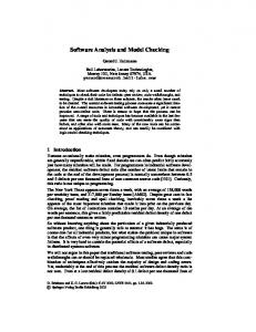
Software Analysis and Model Checking. Gerard J. Holzmann. Bell Laboratories, Lucent Technologies,. Murray Hill, New Jersey 07974, USA.
(x; x0), an assertion over the set of system variables x and a set of primed .... Mutual exclusion for bakery can be expressed as the invariance 2(:(`3^m3)), and ... a falsi cation diagram for S and ' is a directed graph G whose nodes are labeled ...
abstraction, runtime analysis, and slicing with model check- ing. .... Fourth, studying formal methods for programming lan- guages may ... The first version of JPF [20], as well as the JCAT system. [10], were .... the components mentioned above is a
In fact, arbitrary Turing machines can be modelled by means of the parallel composition of ... That model checking is decidable for pushdown processes is also a ...
Jan 15, 1997 - We introduce a symbolic model checking procedure for Probabilistic ... Thus, converting to MTBDDs would ensure smooth integration ..... BDDs replacing the free relational variables (i.e. we fix the interpretation for the free relationa
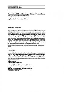
Keywords Software product lines · compositional model checking · variation point · feature ..... If tk satisfies its obligation Ïi, then update the aSet entry for si in FMi. Step 3 If ...... Telecommunications Systems, IOS Press, pp 67â82. Have
path leading to a violation of an assert statement occurring in the original pro- ..... Kroening, D., Clarke, E., Yorav, K.: Behavioral consistency of C and Verilog.
Software product lines are widely used due to their advantageous reuse of .... product line (Section 2) in a compositional fashion, which was not previously possible. ... 2. The implementation stores the variation point obligations obtained for .....
the free name y and having continuation A, just in case fy=xg holds of A. For output of bound names the condition is slightly more complex as in that case both.
(CTL) tailored to formal verification of software for microcontrollers. .... 8 dual-core AMD OpteronTM 8220 processors (2.80 GHz) and 256 GB of RAM, running ...... Dong, Y., Du, X., Ramakrishna, Y.S., Ramakrishnan, C.R., Ramakrishnan, I.V., ...
formizierung nur eine begrenzte Anzahl Schritte berücksichtigt. ... 3.3.2 Uniformization applied to QBDs . ... 4.2.2 Reachability set and atomic propositions . ...... Proc. of the 2004 International Conference on Dependable Systems and Net-.
Hardness for Explicit State Software Model Checking Benchmarks. Neha Rungta ... We show that this is not a good hardness metric because models labeled hard with ... rank the states in order of interest with states estimated to be near errors ...
Sep 6, 2005 - gramming languages (see JPF [16] and SLAM [2, 1]). These ... (i.e. Corba ORB implementations). ...... //displacing the window for (i=0 ...
gorithm are presented for a wide variety of software applications. The proposed. algorithms .... would be equivalent to. the optimisation problem of finding the minimum satisfying K. 3 ..... It is widely used by web browsers, ssh. clients, and other
William Chan, Student Member, IEEE, Richard J. Anderson, Paul Beame, Steve ... W. Chan, R.J. Anderson, P. Beame, and D. Notkin are with the Department.
First a word about the relevance of software model checking techniques in industrial ..... we need a broader definition of acceptance. 2.3. Bu .. chi-acceptance.
Feb 11, 2010 - C, Ada code. 5.D.5-3. Authorized licensed use limited to: University of Minnesota. Downloaded on February 11, 2010 at 13:12 from IEEE Xplore ...
(AGG)-like graph transformation systems are translated to Bandera intermediate representation (BIR), the ... using graphs and graph transformation systems as a.
Oct 17, 2009 - E. âthere exists a pathâ. G p. âp holds globally in the futureâ. pUq ... BLAST (Berkeley Lazy Abstraction Software Verification Tool) is a software ...
model checking properties such as compatibility checking and deadlock analysis .... (V, P) where V is a function mapping a variable name to its value, which we ...
Mar 5, 1999 - [OG76] Susan Owicki and David Gries. Verifying properties of parallel ... [SD98] Ulrich Stern and David L. Dill. Using magnetic disk instead of ...
Mar 14, 2003 - Times are measured in seconds and were taken on a Titanium PowerBook G4 running Mac OS X 10.2.4 with 512 MB of memory, running Java ...
Model Checking of Software Processes Barbara Staudt Lerner Williams College [email protected] March 14, 2003
Abstract Software process and workflow languages are increasingly used to define loosely-coupled systems of systems. These languages focus on coordination issues such as data flow and control flow among the subsystems and exception handling activities. The resulting systems are often highly concurrent with activities distributed over many computers. Adequately testing these systems is not feasible due to their size, concurrency, and distributed implementation. Furthermore, the concurrent nature of their activities makes it likely that errors related to the order in which activities are interleaved will go undetected during testing. As a result, verification using static analysis seems necessary to increase confidence in the correctness of these systems. In this paper, we describe our experiences applying LTSA to the analysis of a process written in Little-JIL. A key aspect to the approach taken in this analysis is that the model that is analyzed is derived directly from the implementation of the Little-JIL interpreter rather than just from the intended semantics of the Little-JIL constructs. This analysis uncovered seven errors in the Little-JIL interpreter that were previously unknown.
1
Introduction
Software is increasingly being constructed by connecting together existing components into a loosely connected framework. In the past, component reuse was accomplished by the use of component libraries where the result of composition was typically a tightly connected system with the components compiled together into a single executable program. While this is still the most common form of reuse, there is increasing interest in component reuse at a larger scale, where the composite system consists of numerous independent programs running on different machines communicating over a network. Two examples of these types of systems are multi-agent systems and business processes built on top of Web services and other existing applications. Business processes are typically built by using a process or workflow language that is capable of describing and carrying out coordination between a collection of applications. The process typically defines data flow, control flow, assignment of responsibilities to applications or to humans, and supports decision making and exception handling activities. As business processes become increasingly important to a business’s success and increasingly complex, it will become important to determine if these processes behave as expected. In many cases, this involves answering the same sort of questions that are often asked about distributed systems. Is deadlock possible? Are there race conditions? Is starvation possible? As a result, it should be possible to apply the same sorts of analysis tools to business processes as to other distributed applications. 1
In this paper, we describe our experiences using model checking to analyze processes written in Little-JIL. Processes written in Little-JIL are hierarchical decompositions of steps into substeps and exception handling steps. The hierarchical nature of the processes suggests that using a compositional approach to building a model for model checking may be an appropriate form of analysis. In addition, the Little-JIL interpreter is implemented as a collection of interacting state machines. This style of implementation has allowed us to prove properties not just about the process specifications, but also about their execution using the interpreter. In this paper, we report on how we derive the models used in model checking from the process and interpreter implementation. We also report on the analysis results we have achieved thus far, including the uncovering of seven errors in the interpreter implementation.
2
Little-JIL
Little-JIL is a process language with a visual syntax[11]. Little-JIL processes describe the coordination of activities carried out by external entities. These external entities may be people, Web services, intelligent software agents, or any other external component that is capable of carrying out requested tasks on input data and reporting the results, whether successfully completed or incomplete due to exceptional situations. We refer to these external entities as agents, independent of their actual realization. A Little-JIL process is executed by interpreting the process specification, selecting agents to perform the tasks, informing the agents of their tasks, sending the necessary data to those agents to carry out their tasks and accepting the return results. Different agents may participate from different machines and may change which machine they are operating from over time. Agents may be requested to perform tasks concurrently. Thus, processes written in Little-JIL are typically executed as distributed, concurrent systems. In this section, we present the aspects of Little-JIL relevant to the model checking analyses we have performed and provide more details on those aspects of the interpreter implementation that are relevant to the model checking.
2.1
The Little-JIL Process Language
The analyses we describe in this article pertain to control flow. As a result, we will describe the control flow semantics of Little-JIL and omit other details of the language. (For a complete description of the language, please see the Little-JIL Language Report[10].) A process is defined as a collection of hierarchically-decomposed steps as shown in Figure 1. A step defines an activity to be performed. It is connected to other steps via substep edges and exception handling edges. Nonleaf steps represent high-level activities that are decomposed into finer-grained activities using substep edges. Leaf steps represent activities that are carried out by external agents with no further work decomposition specified, leaving the agent free to choose exactly how to perform the activitiy. Non-leaf steps use sequencing badges to define the control flow among the substeps. There are four sequencing badges as shown in Figure 2. Sequential steps perform their substeps sequentially from left to right. Parallel steps assign their substeps to agents concurrently. The agents might actually perform the work concurrently or in some unspecified sequential order. Choice steps assign substeps to agents concurrently, but only allow a single agent to perform the assigned work. As soon as one agent begins a choice substep, all other choice substep assignments are retracted. Try steps assign work to agents sequentially but stop as soon as one of the substeps completes successfully. It is possible to attach a cardinality to an edge that connects a step and its substep. Cardinalities specify an upper and lower bound on the number of times the substep should be 2
executed. The lower bound may be 0, meaning that the substep is optional. The default cardinality has an upper and lower bound of 1. If a step cannot be completed successfully, it terminates and throws an exception. The parent of the step can attempt to handle the exception. Exception handling activities are attached to non-leaf steps via exception handling edges. The edges specify which exception the step handles and where control should flow if the exception is successfully handled. There are four possibilities for control flow following an exception as shown in Figure 3. A continue handler indicates that the step should be continued from the point at which the exception was handled, maintaining intermediate results. A restart handler indicates that the step containing the exception handler should be restarted from the beginning, discarding any intermediate results. A complete handler indicates that the step containing the exception handler should be considered to have completed successfully. A rethrow handler indicates that the exception should be rethrown to the parent of the step containing the exception handler. It is possible for an exception handler to have a null step; that is, it identifies the exception being handled and the control flow semantics to use but does not involve any activity to compensate for the exception.
Figure 3: Exception Handling Control Flow
3
Figure 4: Auction Process
Steps may also have prerequisites and postrequisites. Requisites are themselves steps. A prerequisite uses the state of the process to ensure that it is appropriate to execute the step. It is executed prior to a step’s substeps. The substeps are executed only if the prerequisite completes successfully. A postrequisite is intended to check the results of the substeps and only allow the step to complete and make its results visible if this check is passed. A postrequisite is executed after a step’s substeps are completed. Both prerequisites and postrequisites are optional. Every step is assigned to an agent. The agent is the external entity responsible for the step. It is the agent that decides when to start a step and when to skip an optional step. Deciding when to start a step is particularly important for choice substeps as it results in the retraction of the other choice substeps. For leaf steps, the agent is responsible for performing the work associated with the step, returning data results on successful completion of the work, and throwing an exception on unsuccessful completion. Steps may have agent declarations associated with them. These declarations identify the requirements that an agent must satisfy to be allowed to carry out the step. Agent capabilities are described separately in a resource model that is consulted at runtime to find a suitable agent. The root step is required to have an agent declaration. Other steps use the same agent as their parent if they do not have their own agent declaration. In addition to agent declarations, a step may also declare a need for other resources, such as physical resources, networking bandwidth, tool licenses, etc. If there is no agent/resource that meets the needs of a step, or if all such agents/resources are in use at runtime, the interpreter will throw exceptions to indicate this. Figure 4 shows the process used in this experimentation. This process coordinates the actions of an auctioneer and a collection of bidders interacting in an open-cry auction. The auctioneer is responsible for accepting bids and deciding when to close the auction. The bidders are responsible for submitting bids. The Close Auction step runs in parallel with the Accept Bids From Bidder step, meaning that the auctioneer can decide to close the auction at any time. Accept Bids From Bidders is a recursively parallel step. This allows it to
4
Figure 5: The State Machine of a Step Interpreter
accept bids from different bidders in parallel. The Accept One Bid step is sequential. It first checks that the auction is still open via a prerequisite. If it is open, it allows a bidder to submit a bid. If it is higher, the auctioneer updates its record of the best bid. Whether or not the new bid is best, the bidder is then allowed to bid again via the recursive Accept One Bid step if the auction is still open.
2.2
The Little-JIL Interpreter
The Little-JIL interpreter executes a process by instantiating a step, acquiring the agent and resources needed to carry out the step, binding values to its input parameters and then placing the step on the agent’s agenda. There are a variety of mechanisms by which an agent might interact with its agenda. Of importance here, is simply that the agent starts the step. At this point, if a prerequisite is attached to the step, it is instantiated and executed. Assuming it completes successfully, the instantiation and execution activities are repeated on each substep in accordance with the sequencing badge. If a step is a leaf, the agent is expected to perform the necessary work and then either return values for the output parameters and signal success, or throw an exception to signal failure. If the substeps of a step complete according to the semantics of the sequencing badge, the postrequisite is instantiated and executed. If at any point an exception is thrown, the interpreter looks for the lowest ancestor able to handle the exception and instantiates and executes the appropriate exception handling steps. The design of the interpreter is based upon a collection of interacting finite state machines that track the status of the steps. The most important state machines for a step are a StepInterpreter and a Sequencer. The StepInterpreter captures the semantics of step execution that are independent of the sequencing badge while the Sequencer captures the semantics that vary depending on the sequencing badge. There are 5 types of Sequencer machines, one for each sequencing badge plus one for leaves. In total, there are 13 types of state machines within the interpreter. In addition to the major ones listed above, there are machines that interact with the resource manager, evaluate prerequisites and postrequisites, instantiate a step, handle 5
Figure 6: The State Machine of a Sequential Sequencer
exceptions, and clean up a step when it completes.1 A somewhat simplified version of the StepInterpreter machine is shown in Figure 5. While the StepInterpreter is in the state Executing Substeps, the corresponding Sequencer machine is executing as a nested state machine. The SequentialSequencer machine is shown in Figure 6. When the StepInterpreter enters the Executing Substeps state, the Sequencer enters its Instantiating Substep state. When the Sequencer enters its Succeeded state, the StepInterpreter follows the Sequencer Succeeded edge. When the Sequencer enters its Failed state, the StepInterpreter follows the Sequencer Failed edge. It’s important to note that Failed is considered an accepting state of the Sequencer machine, not an error state. It indicates that one of the substeps threw an exception, but the sequencer machine itself reached an acceptable final state. Similarly, the three final states of the StepInterpreter machine are all accepting states. There is also an interaction between the Sequencer and the StepInterpreters for its substeps. This interaction is more complicated as the execution of the substep interpreter corresponds to two states of the interpreter: Instantiating Substep and Executing Substep. In particular, when the Sequencer enters its Instantiating Substep state, the StepInterpreter for the corresponding substep enters its Instantiating state. When the substep’s StepInterpreter enters the Failed state, the Sequencer transitions to the Handling Exceptions state. When a substep’s interpreter enters the Posted state, the Sequencer transitions to the Executing Substep state. When the substep’s StepInterpreter enters the Succeeded state, the Sequencer transitions to the Instantiating Substep state, now interacting with the StepInterpreter for the next substep. This design based upon state machines is carried through to its implementation. The core of the interpreter is defined using state machine definitions. The definitions are input to SMC2 to generate executable Java code. For example, the definition of the INSTANTIATING SUBSTEP state of the SequentialSequencer state machine is shown in Figure 7. On entry to this state, if there are more substeps, the next substep is intantiated. This method call creates a new thread running the StepInterpreter machine for the substep. If there are no more substeps, the Sequential Sequencer machine completes, ending execution of the nested state machine, and sending the sequencerCompleted event to the StepInterpreter machine it is nested inside of. After call1 There
is an additional machine to handle reactions, but that is not included in the experimentation reported here.
2 http://smc.sourceforge.net/
6
INSTANTIATING _SUBSTEP Entry{start();} { start[moreSubsteps();] nil {instantiateNextSubstep();} start[!moreSubsteps();] pop(sequencerCompleted) {} substepInstantiationSucceeded(substep: InterpreterAgendaItem) EXECUTING_SUBSTEP {postSubstep(substep);} substepInstantiationFailed(substep: InterpreterAgendaItem, exceptions: Collection) HANDLING_EXCEPTIONS {addExceptionsToHandle(exceptions);} } Figure 7: The INSTANTIATING SUBSTEP State of the Sequential Sequencer in SMC Syntax
ing instantiateNextSubstep, the sequencer expects to hear either the event substepInstantiationSucceeded or substepInstantiationFailed. In the succeeded case, it executes the action to post the substep, causing the substep’s StepInterpreter to receive the posting event, and then transitions to the EXECUTING SUBSTEP state. If the substep instantiation fails, the sequencer remembers what exception needs to be handled and then transitions to the HANDLING EXCEPTIONS state. The interpreter implementation contains 13 state machines defined in this manner with a total of 68 states. The StepInterpreter state machine has the most states with 21 of them.
3
LTSA
LTSA is a model checker developed by Jeff Kramer and Jeff Magee at Imperial College[8]. The input to LTSA is a set of interacting finite state machines written in their process algebra called FSP.3 Each FSP process definition is translated into a Labeled Transition System for analysis by LTSA. A process is defined in terms of local processes consisting of a list of choices. Each choice may have a condition associated with it, followed by a list of sequential events, and ending with the name of another local process. When two or more processes use the same event, the event is assumed to happen synchronoously in all processes. Figure 8 shows two interacting FSP processes. The first process simulates a clock that issues alternating ticks and tocks. A second process called chime issues a chime periodically where the length of the period is determined by the value passed in as a parameter to CHIME. Using parameterization, the same process can be used in different contexts and result in the generation of different finite state machines. In this case, the CHIME process requires enough states to count by 2 up to its maximum value. Processes as shown in Figure 8 are primitive processes. Primitive processes may be composed to produce composite processes. When composing processes, it is possible to hide some of the events used by the primitive processes and only make visible those required for later synchronization with other processes. This allows the composite process to be minimized, thereby reducing the size of the labeled transition systems that must be analyzed. This helps address problems of state space explosion common in model checking and 3 Unfortunately, both Little-JIL and FSP use the word process but mean very different things. In this section, process means FSP process. In the remainder of this paper, the phrases “Little-JIL process” and “FSP process” will be used to avoid ambiguity.
7
CLOCK = (tick -> tock -> CLOCK). CHIME(MaxValue=10) = COUNT_SECONDS[0], COUNT_SECONDS[seconds:0..MaxValue-1] = (when seconds < MaxValue-2 tock -> COUNT_SECONDS[seconds+2] | when seconds >= MaxValue-2 tock -> chime -> COUNT_SECONDS[0]). Figure 8: Example FSP Process ||MINUTE_ALARM = (CLOCK || CHIME(60)) @{chime}. CHECK_MAIL = (chime -> check_mail -> CHECK_MAIL). ||CHECK_MAIL_EVERY_MINUTE = (MINUTE_ALARM || CHECK_MAIL). Figure 9: A composite process in FSP
is a good approach for modeling systems with a hierarchical organization[2, 12]. Figure 9 shows an example composite process. The MINUTE ALARM process is defined by composing CLOCK and CHIME, passing 60 as the value to count to, and exposing only the chime event. CHECK MAIL models a mail client that checks the mail server for incoming mail whenever the chime goes off. The tick and tock events are not exposed by the MINUTE ALARM composite process. This allows the composite process CHECK MAIL EVERY MINUTE to be minimized to a finite state machine consisting of just two states. If MINUTE ALARM exposed the tick and tock events, the composite process CHECK MAIL EVERY MINUTE would contain 124 states. By hiding the tick and tock events, the composite process can be minimized to a 2-state machine equivalent to the CHECK MAIL process itself.
4
Building Models of Little-JIL Processes for Model Checking
Our goal is to build a model for model checking that is based on the actual interpretation of the Little-JIL process, not just on the intended semantics of the Little-JIL constructs. To do this we translated the state machines implemented in the interpreter into FSP. We parameterized the FSP descriptions so that they can be specialized to the properties of individual steps in a Little-JIL process. Then, by composing these FSP descriptions we can model the entire Little-JIL process, in terms of how the interpreter will execute it. In this section, we provide more information on how this model is constructed.
4.1
Modeling the Interpreter
The major effort in modeling a Little-JIL process is in modeling the interpreter. Due to the state machine based implementation of the interpreter, it is relatively straightforward to develop an FSP model of the
when curSubstep > NumSubsteps parent.sequencerCompleted -> FINAL
| when curSubstep == 1 substep1.instantiationSucceeded -> substep1.requestPost -> EXECUTING_SUBSTEP[curSubstep] | when curSubstep substep2.requestPost -> EXECUTING_SUBSTEP[curSubstep] | when curSubstep == 1 substep1.instantiationFailed -> (substep1.resourceUnknown.throw -> HANDLING_EXCEPTIONS[curSubstep] | when curSubstep (substep2.resourceUnknown.throw -> HANDLING_EXCEPTIONS[curSubstep]) Figure 10: The INSTANTIATING SUBSTEP Local Process of the Sequential Sequencer in FSP STEP_INSTANTIATOR = (requestInstantiate -> instantiate -> STEP_INSTANTIATOR | final -> STEP_INSTANTIATOR) Figure 11: Model of the Thread that Instantiates a Step
interpreter. Each state machine in the interpreter corresponds to an FSP process. Each state in an interpreter state machine corresponds to a local FSP process. Each FSP process is parameterized so that it can perform conditional tests equivalent to those performed by the state machines. Actions that result in the sending of events between state machines, such as posting a substep, are modeled by adding those events to the FSP descriptions. For example, consider the FSP equivalent of the INSTANTIATING SUBSTEP state shown in Figure 10. The INSTANTIATING SUBSTEP local process is parameterized by the index of the step currently being executed. The SEQUENTIAL SEQUENCER process (not shown) has NumSubsteps as a parameter. The model for each sequential step includes a SEQUENTIAL SEQUENCER process, passing in the number of substeps it has as a parameter. Note also that choices must be repeated for each potential substep. The model shown here would work for steps containing 0, 1, or 2 substeps. (In the case of 0 substeps, the INSTANTIATING SUBSTEP local process is not reachable.) Extending the model to support a larger number of substeps is straightforward. The model used in the analysis reported here supports up to 3 substeps. The requestInstantiate event models the activities of the instantiateNextSubstep action. The requestPost event models the activities of the postSubstep action. The resourceUnknown.throw event models the activities of the addExceptionsToHandle event. Each time that a state machine starts in the interpreter, it is run in a new thread. To model this, each step instantiates its own FSP process by supplying the appropriate parameter values. In addition to these
9
||CloseAuction = (closeAuction:STEP_INTERPRETER(False,False,Leaf,Parallel,False)/ {final/closeAuction.final,openCryAuction/closeAuction.parent} || {closeAuction}::LEAF_SEQUENCER(False,False,False)/ {final/closeAuction.final} || {closeAuction}::AGENT(Parallel,Leaf,False,False,False,False,False)/ {final/closeAuction.final} || {closeAuction}::STEP_POSTER(Parallel)/ {final/closeAuction.final,openCryAuction/closeAuction.parent} || {closeAuction}::STEP_ELABORATOR/{final/closeAuction.final} || {closeAuction}::ELABORATOR(0,False,False)/ {final/closeAuction.final} || {closeAuction}::FINALIZER(0,0,Leaf)/{final/closeAuction.final}. Figure 12: The FSP Model of the CloseAuction Step
Step OpenCryAuction CloseAuction AcceptBidsFromBidder AcceptOneBid SubmitBid Update Best Bid Total
Before minimization States Transitions 367 614 44 73 438 728 387 1141 126 225 41 56
After minimization States Transitions 11 13 15 31 31 63 37 69 33 65 13 21
Composition time (sec) 0.8 1.0 0.9 1.0 0.8 0.9 5.4
Minimization time (sec) 3.2 0.1 27.4 1.4 0.3 0.1 32.5
Table 1: Sizes of the Models of the Steps in the OpenCryAuction process and Time to Create Them state machine threads, four actions taken by the state machines result in the creation of new threads. Two appear in the example above: step instantiation and step posting. The FSP model includes models of these threads as well. Figure 11 shows the model for the thread that instantiates a step. The requestInstantiate event synchronizes with the FSP process doing the instantiation, in this case the sequencer for the parent of the step being instantiated. The instantiate event synchronizes with the StepInterpreter process for the step being instantiated. FSP processes for the other three machines are quite similar but involve different events. The FSP model of the interpreter contains 17 processes corresponding to the 13 interpreter state machines plus the 4 helper threads mentioned above. In addition, the FSP model contains a process describing agent behavior, specifically placing the agent in charge of deciding when to start a step, when to opt out, when to complete successfully, and when to throw an exception. In total, there are 96 local FSP processes. There are more local processes in the FSP definition than states in the SMC definition for several reasons. The FSP definition contains 5 additional processes (the agent and 4 helper threads). The FSP definitions have an additional FINAL state. In some cases it was necessary to add states to model activities that were done in Java actions. These primarily revolved around throwing and handling exceptions. Finally, in the case of the choice sequencer, it was necessary to replicate an entire state for each child of the substep, not just replicate transitions as shown earlier. In summary, the FSP model was built directly from the implementation. While including somewhat more functionality than just the SMC definitions, the connection between the two representations is very clear and represents a faithful model of the interpreter implementation.
10
4.2
Modeling a Little-JIL Process Using FSP
To model a Little-JIL process, we create a model of each step using the step name to distnguish one step model from another. We then compose the step models, renaming parent and substep event prefixes to the appropriate step names to create a model of the entire Little-JIL process. Each step model is itself a composition of primitive FSP processes. In particular, each step is modeled with a StepInterpreter, a Sequencer, an Elaborator, a Finalizer, an Agent, a StepInstantiator, and a StepPoster. Depending on the characterisitics of the step, additional primitive processes, such as a PrerequisiteEvaluator or ExceptionHandler may also be included. Figure 12 shows the model for the CloseAuction step of Figure 4. The parameters provide information to the primitive processes about the details of the step. For example, the parameters to the STEP INTERPRETER indicate that the step has no prerequisite, acquires no resources, is a leaf, has a parallel step as a parent, and has no postrequisite. Following the parameters are the renamings used to allow events in this FSP process to synchronize with events from other FSP processes. All FSP processes have a final event which occurs when the root step completes to indicate that there will be no more opportunities for any FSP process to execute again. The second renaming for the STEP INTERPRETER demonstrates how steps and substeps are bound together. The STEP INTERPRETER uses parent as a prefix for events it expects to synchronize with its parent. When we do the composition, we rename closeAuction.parent to openCryAuction, the name of the parent step. Other steps are composed in a similar way. When composing a non-leaf step, the FSP processes containing the models of its substeps are included in the composition. Recursive steps require special attention. We create a distinct model for each occurrence of a recursive step. Most of these will essentially be duplicates of each other until the final step that forces the recursion to stop. Using the approach described above, we have modeled the auction process shown in Figure 4. In this model, we unrolled each recursive step once. While this model was built by hand, it is clear that generating FSP models from Little-JIL processes is easily automatable. The primitive processes representing the interpreter and the agent model are the same for all Little-JIL processes. Modeling a step is simply a matter of composing the appropriate primitive processes, providing the necessary parameters, and doing the necessary label renaming. All of these are easily determined by examining the step’s static definition. The person performing the analysis would need to specify a bounds on each recursive step so that the recursion could be unrolled the proper number of times. Modeling a Little-JIL process is then just a matter of composing these step models together, which is again easily automatable. Table 1 shows the sizes of the models created by LTSA before and after minimization for each step in the auction process shown in Figure 4. The Little-JIL process model is composed from the leaves up. A leaf step consists of a composition of primitive interpreter processes. A non-leaf step consists of a composition of primitive interpreter processes as well as the minimized model of its substeps. Composition time indicates how long it took to compose the model for the step, while minimization time is the time to minimize the model after it is composed. Times are measured in seconds and were taken on a Titanium PowerBook G4 running Mac OS X 10.2.4 with 512 MB of memory, running Java 1.3.1. The times are based on a model of the interpreter that corrects the errors reported below, resulting in no deadlocks or violated properties. The time to check the model of the OpenCryAuction once the model is created is 12 ms.
5
Proving Properties of Little-JIL Processes
After building the FSP model of the Little-JIL auction process, we then used LTSA to check for deadlock and to check properties about the interpreter implementation. Through analysis with LTSA we have identified 7
11
previously unknown errors in the interpreter implementation. Two of these could have been uncovered given the right test input, while the remaining five would only be apparent if a particular interleaving of events from concurrent threads occurs. We find this result to be particularly exciting given that these errors never surfaced in the testing or routine use that the interpreter has undergone in the past several years.
5.1
Interpreter Deadlocks Found
Most of the errors that were found were uncovered during deadlock detection. One design problem is responsible for three of these errors so we will discuss those in more detail. All substeps of a parallel step may be executed concurrently. The intepreter posts them concurrently, but agents are responsible for deciding exactly when they execute. If a substep of a parallel step throws an exception, any other substeps that have not been started yet by an agent are retracted while the exception is being handled to avoid doing work that is potentially unnecessary. Retracting a step is done using a helper thread similar to step instantiation and posting. The Sequencer of the parent synchronizes with this thread using a requestRetract event. The StepInterpreter of the child synchronizes with the retracting event. Because retraction is done in a separate thread there can be an arbitrarily long time between when the parent sequencer requests the retraction and the substep actually retracts. This sets up the possibility of races, some of which result in deadlock:
• If the parent’s finalizer starts (meaning the step is cleaning up) before the substep retracts, the substep never gets canceled as it should be. • The exception handler of parallel steps assumes that steps retract before the exception handler runs, but there is no synchronization in the interpreter to assure this. This leads to two problems: – A substep may start while the parent’s exception handler is running, which is in violation of language semantics. – If an agent opts out of a substep after the parent’s exception handler starts, the exception handler deadlocks. If the step was retracted, opting out would not be an option.
5.2
Violations of Interpreter Properties
We defined nine properties that we wanted to prove about the interpreter. These properties include such things as assuring that the prerequisite is checked prior to executing substeps. Of these nine properties, two uncovered errors in the interpreter. One property is again related to substep retraction so we discuss it here. This property states that a sequential or parallel step can only complete successfully if one of the following holds:
• All children complete successfully, or • All exceptions thrown by substeps are handled with complete or continue control flow semantics.
This property was included in the composition for all parallel and sequential steps. In attempting to prove it, we discovered another race condition involving retraction of substeps of parallel steps. Specifically, if the parent’s exception handler runs and decides to continue the step, it will think there is no more work to do and complete the step if the substeps that should be retracted are not yet retracted.
12
6
Related Work
Modeling and verifying the behavior of concurrent systems is a very active research area. There is much less work on the analysis of process languages, particularly executable process languages. FunsoftNets[1] and Process Landscaping[6] are two approaches to verifying properties of processes based on Petri net models. Statemate[7] has sophisticated analysis techniques but operates on specifications of systems rather than their actual implementations. The most directly related work is the work of Jamieson Cobleigh who applied FLAVERS[5] to the analysis of the same auction process[3] as presented in this paper. His goal was to prove process-specific properties. The model of the auction process used in this work was built by hand based upon the intended semantics of LittleJIL constructs rather than their actual implementation. As a result, while he made progress in the analysis of process-specific properties, he did not uncover the interpreter errors reported in this paper. Furthermore, the translation of Little-JIL to the TFG model required as input to FLAVERS is less straightforward than the translation to FSP, meaning that automating this translation will be more difficult. On the other hand, Cobleigh did evaluate process-specific properties, which is work we are just beginning and thus cannot yet compare these two approaches adequately.
7
Future Work
The goal of this work is to be able to prove process-specific properties. We chose the auction process in order to replicate the experiment carried out by Jamieson Cobleigh in applying the FLAVERS dataflow analyzer to the analysis of Little-JIL processes. Because of the nature of the state machine based implementation of the interpreter and the hierarchical nature of Little-JIL processes, applying LTSA seemed like an appropriate analysis approach to try. As described here, most of our effort has involved developing an accurate model of the interpreter thus far. We are now beginning to analyze the same process-specific properties as reported in Cobleigh’s paper, in which some results are inconclusive. We are interested in comparing the results of the two analysis techniques. Another approach to verification that we are interested in pursuing is compositional verification based on an assume-guarantee style of reasoning[9]. Cobleigh, et al. have built a system on top of LTSA to support this style of reasoning that learns the assumptions that must hold about an environment in order to prove a property about a component[4]. We are very interested in applying their tool to compare the effectiveness of these two styles of verification.
8
Conclusions
Model checking operates on a model that abstracts away some details of the code. One of the challenges in model checking is to create a model that is sufficiently abstract to remain computationally feasible while sufficiently detailed to capture the semantics of the application that are being verified. Little-JIL provides such an abstraction for applications that involve the coordination of multiple agents by focusing on the coordination issues and abstracting away the details of agent behavior. Furthermore the style of implementation of the Little-JIL interpreter has given us the ability to model Little-JIL processes in terms of their execution behavior, not just in terms of the intended semantics of the Little-JIL constructs. Our results in uncovering errors in the implementation of the interpreter suggest that this style of implementation along with the hierarchical nature of Little-JIL processes is well-suited to the compositional approach provided by LTSA.
13
Acknowledgements Little-JIL was designed and developed by members of the Laboratory for Advanced Software Engineering Research at the University of Massachusetts, Amherst under the guidance of Lee Osterweil. The state machine design of the interpreter was done chiefly by Sandy Wise, Eric McCall, and Aaron Cass. Aaron was responsible for the state machine based implementation of the Little-JIL interpreter using SMC. The auction process was developed by Aaron, Sandy and Hyungwon Lee and previously appeared in an ISSTA paper. Jamieson Cobleigh has given me helpful tips on how to use LTSA effectively. Finally, I would like to thank Rick Lerner, Jamie and Aaron for their comments on an earlier draft.
References [1] A. Br¨ockers and V. Gruhn. Computer-aided verification of software process model properties. In Proc. of the 5th Intl. Conf on Advanced Information Systems Eng., pages 521–546, 1993. [2] S. C. Cheung and J. Kramer. Checking safety properties using compositional reachability analysis. ACM Trans. on Soft. Eng. and Methodology, 8(1):49–78, Jan. 1999. [3] J. M. Cobleigh, L. A. Clarke, and L. J. Osterweil. Verifying properties of process definitions. In Proc. of the Intl. Symp. on Software Testing and Analysis (ISSTA), pages 96–101, Portland, Oregon, August 2000. [4] J. M. Cobleigh, D. Giannakopoulou, and C. S. P˘as˘areanu. Learning assumptions for compositional verification. In Proc. of the 9th Intl. Conf. on Tools and Algorithms for the Construction and Analysis of Systems, April 2003. [5] M. B. Dwyer and L. A. Clarke. Data flow analysis for verifying properties of concurrent programs. In Proc. of the ACM SIGSOFT ’94 Symp. on the Foundations of Soft. Eng., pages 62–75, December 1994. [6] V. Gruhn and U. Wellen. Process landscaping: Modeling distributed processes and proving properties of distributed process models. In Unifying Petri Nets - Advances in Petri Nets, number 2128 in Lecture Notes in Computer Science. Springer Verlag, December 2001. [7] D. Harel, H. Lachover, A. Naamad, A. Pnueli, M. Politi, R. Sherman, A. Shtull-Trauring, and M. Trakhtenbrot. STATEMATE: A working environment for the development of complex reactive systems. IEEE Trans. on Soft. Eng., 16(4):403–414, April 1990. [8] J. Magee and J. Kramer. Concurrency: State Models and Java Programs. John Wiley & Sons, 1999. [9] A. Pnueli. In transition from global to modular temporal reasoning about programs. In K. Apt, editor, Logic and Models of Concurrent Systems, volume 13, pages 123–144, New York, 1984. Springer Verlag. [10] A. Wise. Little-JIL 1.0 language report. Technical Report TR 98-24, University of Massachusetts, Department of Computer Science, 1998. [11] A. Wise, A. G. Cass, B. S. Lerner, E. K. McCall, L. J. Osterweil, and J. Stanley M. Sutton. Using Little-JIL to coordinate agents in software engineering. In Proc. of the Automated Soft. Eng. Conf. (ASE 2000), pages 155–164, Grenoble, France, September 2000. [12] W. J. Yeh and M. Young. Compositional reachability analysis using process algebra. In Proc. of the Symp. on Testing, Analysis, and Verification (TAV), pages 49–59, October 1991.