details in the process of modeling automotive software systems. On the one hand, the challenge is to find abstractions that are high-level so that as many details.
Model-Driven Development of FlexRay-Based Systems with the Timing Definition Language (TDL) Andreas Naderlinger1), Johannes Pletzer1), Wolfgang Pree1,2), Josef Templ1) 1)
preeTEC GmbH, Nico-Dostal-Str. 6, 5020 Salzburg, Austria {Andreas.Naderlinger, Johannes.Pletzer, Wolfgang.Pree, Josef.Templ} at preeTEC.com www.preeTEC.com 2) C. Doppler Laboratory Embedded Software Systems, Univ. Salzburg Jakob-Haringer-Str. 2, 5020 Salzburg, Austria www.cs.uni-salzburg.at
Abstract This paper argues that a logical specification of the timing behavior, which represents the core abstraction of the Timing Definition Language (TDL), is the key to significantly reduce the development, maintenance and integration costs of FlexRay-based systems. We measured a productivity gain by a factor of 20 and more with TDL compared to state-of-the-art FlexRay development methods and tools (see Section 1). We illustrate how TDL allows the platform-independent modeling of the timing and functional behavior, and how we accomplish the automatic platform mapping. An outlook sketches future research activities.
1. Platform-neutral modeling with TDL A development methodology that deserves the attribute model-driven needs to support the platform-neutral design and simulation of software components. In other words, model-driven development of embedded automtotive software requires appropriate domain abstractions. They allow developers to ignore nasty details in the process of modeling automotive software systems. On the one hand, the challenge is to find abstractions that are high-level so that as many details as possible can be ignored. On the other hand, these abstractions must not be too disconnected from the underlying system so that efficient code can be generated out of the models. The Timing Definition Language (TDL) [6, 7, 12] is a pioneering domain-specific high-level modeling language for portable and deterministic hard real-time control systems, such as active rear-steering systems or x-by-wire systems. A TDL program explicitly specifies
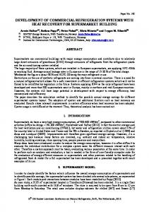
the exact real-time interactions of software components with each other and the physical world. The TDL compiler and bus schedule generator automatically generate the timing code and bus schedule(s) that ensure that the specified behavior on a given platform is equivalent to the one in the modeling and simulation phase, provided the platform offers sufficient computing and communication resources. Figure 1 illustrates schematically the consequence of model-driven development with TDL. In TDL a component, for example, called M1, is developed once. The automatic code generators allow the deployment on any platform with sufficient computing and communication resources. In case of FlexRay, M1 could be deployed on a FlexRay cluster1 with Motorola’s PowerPC computing nodes and the realtime operating system AES from DeComSys [11] or on a FlexRay cluster2 with MicroAutoBox nodes from dSpace.
Figure 1. A platform-independent TDL component M1 versus platform-specific components.
This TDL development process is in stark constrast to state-of-the-art approaches which require the definition of a platform and a topology as a first step. Then the software components are tailored to that specific platform and topology. A platform change, and even a change of the topology alone, that is, adding or removing a node, typically implies a development from scratch. Thus, M1 becomes tightly coupled with the particular platform: M1a is the software for platform variant a, M1b for variant b, etc. We measured how much time it takes to come up with a system that executes on a FlexRay cluster with the DESIGNERPRO tool from DeComSys (used by a developer with in-depth experience with that tool chain) and compared it with the time it took to solve the same problem with the TDL tools, again used by a developer with in-depth experience with the TDL tool chain. The result is that the development time is 20 times less with TDL compared to the state-of-the-art approach. This was measured for a simple case study where only a value is communicated from one node to another node and then sent back to the original node. Thus, the bus schedule is fairly simple. For more complex problems we assume that the TDL approach might even lead to higher productivity gains compared to manual scheduling and parameter setting. Logical Execution Time abstraction. The programming model of TDL relies on the socalled Logical Execution Time (LET) [3, 4] abstraction, invented in the realm of the Giotto project [1, 4, 5] at the University of California, Berkeley. The inputs of a periodically executing task are read at the beginning of the LET period and the newly calculated outputs are available at the end of the LET period. Between these, the outputs have the value of the previous execution. LET means that the observable temporal behavior of a task is independent from its physical execution. It is only assumed that physical task execution is fast enough to fit somewhere within the logical start and end points.
Figure 2. Schematic representation of a TDL module.
TDL component model. Figure 2 illustrates a TDL component (= module): a TDL module forms a unit that consists of sensors, actuators, and modes. A TDL module typically corresponds to one automotive system (sometimes refered to as ‘function’) such as an active rear-steering system. A TDL module is in one mode at a time. A mode is a set of periodically executed activities. The activities are task invocations, actuator updates, and mode switches. All activities can have their own rate of execution and all activities can be executed conditionally. The timing definition after each task’s name is the particular LET. The tasks represent the functionality, particularly the control laws. Any suitable language can be chosen to implement the functionality. If MathWorks’ tools are used, the task functionality is modeled in Matlab®/Simulink® from which C code can be generated. In TDL actuator updates and mode switches are considered to be much faster than task invocations, thus they are executed in logical zero time, whereas task invocations adhere to the LET semantics. All communications between tasks and between modules (not shown in Figure 2) adhere to LET semantics. Note that TDL modules correspond to parallel automata that can switch their operation mode independently.
Figure 3. ARS system model with two TDL components.
Sample TDL components. Figure 3 shows a sample Matlab®/Simulink® model of an Active Rear Steering (ARS) system. The ARS system is courtesy of MagnaSteyr Fahrzeugtechnik [2]. The model consists of the two TDL modules RearActuatorController and VehicleDynamics and a subsystem Vehicle that represents the ‘plant’, that is, the relevant aspects of the vehicle that needs to be controlled. The TDL module RearActuatorController controls the DC motor of the rear axis. The TDL module VehicleDynamics computes the desired value of the rear steering angle, based on the following sensor data: the steering angle of the front wheels, the car speed (both of which are set by the human driver), and the yaw angle of the car. For a detailed description of the ARS case study, in particular how to specify the timing and functionality for each TDL module we refer to [13].
2. Mapping TDL components to a FlexRay platform The principal concept of the platform mapping results from the fact that a set of TDL modules modelled in Matlab®/Simulink® can be mapped to any number of specific platforms. In order to map a set of TDL modules to a specific platform, the user puts a Distribution block from the Simulink® Library Browser to the particular model by dragging it from the library to the model (see Figure 4). In our example, we name the block AES-FlexRay platform as we want to map the two TDL modules to a FlexRay cluster [9] with the socalled AES operating system [11]. Note that any number of platform mappings can be defined for a model. To map the modules, for example, to a FlexRay cluster from dSpace GmbH, the user would drag another Distribution block from the Simulink® Library
Figure 4. Adding a Distribution block to the ARS system model.
Browser, drop it on the model and specify the platform as well as the particular module-to-node mapping. A double-click on the TDL Distribution block opens the TDL:VisualDistributor tool (see Figure 5). It already contains the TDL modules RearActuatorController and VehicleDynamics defined in the ARS model where the Distribution block was inserted.
Figure 5. TDL:VisualDistributor tool with the TDL modules.
In order to assign the TDL modules to nodes of a platform we need to define the platform first. The TDL:VisualDistributor offers the editing features to define the topology and properties of distributed platforms that are common in the automotive domain. For a demo video that illustrates how to define a FlexRay platform we refer to the Web [12]. The TDL:VisualDistributor can also save and load platforms. In this case study we assume that a platform that describes a FlexRay cluster with two MPC5554 nodes as ECUs, each running the AES operating system, has already been defined. We load that platform and can then assign the two TDL modules to the two nodes of that particular FlexRay cluster.
3. Automatic bus schedule generation
Figure 6. Mapping of TDL modules to ECUs connected with a FlexRay bus.
The TDL:VisualDistributor accomplishes the automatic generation of all files that are required to build the executable(s) for the specific platform. In case of the FlexRay-AES platform we need, for example, the platform-independent TDL source code for modules M1 and M2, the C code (generated with Real-Time-Workshop Embedded Coder) for each task function of each TDL module, the FIBEX file representing the bus schedule, the FlexRay-specific configurations and the makefiles. For that purpose we simply choose the Build All menu item in the File menu (see Figure 7).
Figure 7. Code and bus schedule generation.
After compiling the code and uploading it to each of the nodes the system behaves as simulated in the TDL:VisualCreator. As TDL modeling means simply setting the LET periods of tasks, and as the user does not have to define a bus schedule and the numerous FlexRay details, TDL together with the automatic generators reduces the development effort by a quantitatively measured factor of 20 and more compared to state-of-the-art methods and tools, if a FlexRay-system is developed from scratch.
The timing definition, expressed as logical execution time intervals for each task of a TDL module, is the starting point for bus schedule generation. If a user specifies with the TDL:VisualDistributor tool that two TDL modules execute on separate nodes and if the one receives information from the other, a generated schedule is correct if sending and receiving is accomplished so that the LET semantics is preserved. One of the challenges when implementing the automatic mapping of TDL modules to a distributed platform is to come up with a scalable bus schedule generator. Remember that each TDL module can switch its mode independently of other TDL modules. Due to a combinatorial explosion of bus schedules it would not be feasible to generate a separate bus schedule for each combination of modes of a predefiined set of TDL modules. This section describes an approach that we have called Dynamic Multiplexing as basis to come up with a scalable bus schedule generation algorithm. Fibex Multiplexing versus Dynamic Multiplexing. Figure 8a illustrates the known multiplexing concept as described in the FIBEX standard [8]. We assume that a frame is sent at three successive times. Each one has the statically determined switch and data spaces with exactly the same length and same position within frame f, no matter when it is sent. Only the contents of the switch and data spaces can vary. In the following we call the switch space tag, and the data space message. They form what we call a tagmessage group. Figure 8b exemplifies Dynamic Multiplexing. At t1 only one tag-message group is sent in frame f. At t2 two tag-message groups are sent. The message in the first tag-message group has a different size than the message sent at time t1. The message of the second tag-message group sent at t2 has also a different size than the message of the first tag-message group. In an analogous way the tag-message groups sent in frame f at time t3 differ from each other and the tag-message groups sent in frame f in the previous time instances t1 and t2. In other words, the Fibex multiplexing is only one special case of Dynamic Multiplexing.
Figure 8. Multiplexing according to the FIBEX standard (a) versus Dynamic Multiplexing (b).
Preliminaries for bus schedule generation. We assume that the access to the shared communication medium is collision free via a TDMA (Time Division Multiple Access, [9]) approach. Furthermore, we adhere to the Producer/Consumer model. This means that the nodes that generate information—the producers—trigger the sending of information over the network. The nodes that need the information—the consumers—do not send any requests to the producers as it is the case in the Request/Response model. Mode switch instants per module. LET-based description languages such as TDL restrict mode switches such that task invocations are never interrupted by a mode switch. Thus, mode switches are said to be harmonic, that is, a mode switch must not occur during the LET of every task invocation of the currently active mode. Therefore, the period of a mode switch must be a multiple of the LCM (least common multiple) of the period of tasks invoked in this mode. This check is done during compilation. Furthermore, the mode period is always a multiple of the periods of task invocations and mode switches. For a given module M, we define mspGCD M as the GCD (greatest common divisor) of mode periods and mode switch periods in all modes in M. We know that within the time span [N*mspGCD M .. (N+1)*mspGCD M] there will not be a mode switch within module M. In other words, we can express the mode switch instants as an integer multiple of mspGCD M. Bus period. As we generate a static schedule, the size of the schedule needs to be finite. Thus, the schedule is repeated periodically. We call the time span covered by the schedule the bus period. As each mode in every module may have its specific communication requirements, an obvious candidate for the bus period is the longest time span without a mode switch in any module. Thus we
calculate the bus period as GCD of the mspGCDM of each module M which communicates on the bus. Each mode period consists of an integer multiple of bus periods and we introduce the term phase in order to distinguish these mutually exclusive parts of a mode. Messages. We define the term message as the collection of all values of the task output ports produced by a TDL task invocation. Each task invocation produces one message. Note that if a task is invoked N times per mode period, N messages are produced. As an optimization, task output ports that are not used by any client are ignored. Furthermore, tasks that are not public or that have no clients produce no messages. Each message has individual timing constraints. The release constraint is the earliest time instant message sending can be started. The deadline constraint of the message is the latest time instant when the message sending must be finished. Frames per TDL module. In order to use the communication medium efficiently, we map the messages of a phase to one or more reserved communication windows within the bus period such that these communication windows can be used for all phases of a module. A reserved communication window corresponds to a frame, which is the unit of information to be sent on the bus. The schedule generator determines the frames and binds each message to exactly one frame. At run-time, the phase of a module determines which subset of the messages bound to a frame is actually sent. The release (r) constraint of a frame is the maximum of the release constraints of the bound messages. The deadline (d) constraint of a frame is the minimum of the deadline constraints of the bound messages. The schedule generator guarantees that the frame size as well as the release and deadline constraints are sufficient for the communication requirements of all phases.
4. Status and outlook The TDL:VisualCreator and TDL:VisualDistributor tools are available as products. We are currently implementing the mapping to different specific FlexRay platforms, including the AUTOSAR-FlexRay stack. Our research efforts focus on refinements of incremental bus schedule generation, which allows the import of existing bus schedules to TDL tools and the extensions of the bus schedules.
5. References [1] Giotto Project, embedded.eecs.berkeley.edu/giotto/ [2] Magna Steyr Fahrzeugtechnik: www.MagnaSteyr.com/ [3] C.M. Kirsch, 2002, Principles of Real-Time Programming. In Proceedings of EMSOFT 2002,Grenoble LNCS, 2491. [4] Thomas A. Henzinger, Benjamin Horowitz, and Christoph M. Kirsch. Embedded control systems development with Giotto. Proceedings of the International Conference on Languages, Compilers, and Tools for Embedded Systems (LCTES), ACM Press, 2001. [5] T.A. Henzinger, C.M. Kirsch, M.A.A. Sanvido, and W. Pree. From control models to real-time code using Giotto. IEEE Control Systems Magazine 23(1):50-64, 2003. [6] J. Templ, 2007, TDL Specification and Report. Technical Report, on the Web at http://www.preeTEC.com [7] E. Farcas, C. Farcas, W. Pree, J. Templ. Transparent Distribution of Real-Time Components Based on Logical Execution Time, Proc. of ACM SIGPLAN/SIGBED Conference on Languages, Compilers, and Tools for Embedded Systems (LCTES), ACM Press, 2005, pages 31-39 [8] FIBEX standard: www.asam.net/ [9] FlexRay standard: www.flexray.com/ [10] AUTOSAR standard: www.autosar.org/ [11] DeComSys GmbH: www.decomsys.com/ [12] preeTEC GmbH: www.preeTEC.com/ [13] W. Pree, J. Templ: Modeling with the Timing Definition Language (TDL). Automotive Software Workshop San Diego (ASWSD), 15–17 March 2006.