2011 Ninth IEEE/IFIP International Conference on Embedded and Ubiquitous Computing
Model-Driven Development of Wireless Sensor Network Applications Taniro Rodrigues1, Priscilla Dantas1, Flávia C. Delicato2, Paulo F. Pires2, Luci Pirmez2, Thais Batista1, Claudio Miceli2, Albert Zomaya3 1
Federal University of Rio Grande do Norte, 2Federal University of Rio de Janeiro, 3The University of Sydney {tanirocr, pridnt, fdelicato, paulo.f.pires, luci.pirmez, cmicelifarias, tbatista}@gmail.com
[email protected] each application, preferably via high-level models that abstract way features of underlying platforms and allow developers to represent their domain needs using languages that they are familiar to. We argue that a promising solution to facilitate the developing of WNS applications and to promote a clear and synergetic separation between the requirements’ specification at the application level and such specification in a given sensor platform is to adopt the Model-Driven Development (MDD) approach, more specifically the Model-Driven Architecture (MDA) [16]. By adopting a MDA approach, WSN systems can be broken down into levels of abstraction dependent or not on the sensor platform, and the design of each level is in charge of their respective expert. Besides, the MDA approach promotes the reuse of software artifacts independently of the target platform which the system will run in. This paper presents a MDA infrastructure and associated development process to build WSN applications that deal with the above mentioned issues. The goals of our work are threefold: (i) to facilitate the development of WSN applications, thus contributing to the wide spread of such networks in all their potential domains, (ii) to promote the separation of responsibilities between the different experts involved in building such applications; and (iii) to promote the reuse of software artifacts comprised in WSN systems. In this paper we explore the benefits of our proposal in terms of the stated goals by building two applications using two different sensor platforms. The remainder of this paper is organized as follows. Sections II and III present our proposal, including the proposed MDA infrastructure and process to develop WSN applications. Section IV describes the evaluation. Section V depicts related work and Section VI concludes the paper.
Abstract — Developing Wireless Sensor Networks (WSN) applications is not an easy task, since it demands different expertise and knowledge. To address this problem, we propose a model-driven approach to build WSN applications. It promotes the separation of concerns between two levels of requirements involved: (i) domain experts, with no knowledge on WSN platforms, contribute to the development of applications; (ii) network experts, with no knowledge on the application domain, program nodes to meet application requirements. Our approach also promotes the reuse of software artifacts: an application model can be reused on different sensor platforms and a platform model can be reused for different WSN applications. Keywords — WSN; Model; DSL; MDD; MDA
I. INTRODUCTION There are currently several platforms that support the development and implementation of wireless sensor networks (WSN) applications, each one having its own requirements, execution and programming environments and software tools. WSN applications are developed according to two points of view. The first is the application domain expert view (oceanographers, engineers, etc.) and the second is the network experts. Nowadays, application developers need to know several network specificities to build programs either by using the low-level abstractions provided by the sensor OS or directly over the hardware. The high coupling between the application logic and the underlying sensor platform, along with the lack of a methodology to support the development lifecycle of WSN applications resulted in projects with platform dependent code that are hard to maintain, modify, and reuse. Therefore, building WSN applications imposes several challenges to the developer, requiring on the one hand, specific knowledge of WSN platforms and the need to deal with low level abstractions, and on the other hand, specific knowledge about the application domain. It is not usual that a same developer has expertise in both areas. Considering that the same WSN physical infrastructure is potentially useful for a wide range of applications, it would be advantageous to design WSN systems able to support different applications running (either simultaneously or not) in the already deployed nodes. The nodes of these networks must be programmed for 978-0-7695-4552-3/11 $26.00 © 2011 IEEE DOI 10.1109/EUC.2011.50
II. THE WSN MDA INFRASTRUCTURE In our infrastructure, the application domain knowledge is represented at the PIM level through a Domain Specific Language (DSL) [8]. This DSL is defined by the PIM meta-model that describes the semantics of the necessary and sufficient elements to build WSN applications regardless the implementation platform. The knowledge representing different sensor platforms is specified at the PSM level. Therefore, the 11
Despite several positive characteristics, this DSL lacks some important elements that must be considered when developing WSN system. Thus, we introduced new elements into the DSL originally proposed in [15]. The major changes made on the DSL were the insertion of the following elements [1]: (i) Actuator: a component to represents actuators (nodes that instead of only passively sense the environment are able to perform concrete actions on it), that can be of two kinds: Shaker or Relay. Shakers are vibration generators which can be used to analysis or tests in SHM applications. Relays are basically electronic switches; (ii) DataDeliveryUnit: responsible for controlling the strategy for sending data (replacing the previous version of the CommUnit component) from a sensor node to another sensor node or a sink. This component is composed of the following attributes: modelDelivery, which details how the data delivery will be made (continuous, event-driven, request-reply or periodic); rate, if the data delivery is periodic, the developer has to stipulate the schedule rate; eventStatement, if the data delivery is event-driven, the developer has to specify which event will trigger the data delivery. Beyond the attributes, this component has a composition relationship (named packet) with the DataPacket component; through this relationship is possible to define the data packet and choose which application attributes will be sent inside the data package; (iii) LedsUnit: it allows the control of nodes LED (on/off), previously unavailable. LEDs are a very important feature since they are usually the user’s unique communication interface once the application is deployed; (iv) RadioConfigurationUnit: a specialization of FunctionalUnit component introduced to allow a finer grainer control of the energy usage on the sensors radio (controls the duty cycle of the radio); (v) AggregationUnit: a new functional unit, which can be used to represent data aggregation procedures using basic functions like Maximum, Minimum and Average; (vi) DecisionUnit: introduces a control flow operation for the application, increasing the range of WSN applications that can be defined by our DSL.
proposed MDA infrastructure encompasses different PSM meta-models, one for each WSN platform. In the proposed MDA process, application domain experts are in charge of modeling the PIM (and make further refinements in the final code). Then, a first set of (semi)automatic transformations take as inputs this PIM, along with the PSM meta-model of the chosen sensor platform, and generate a PSM instance that represents the application logic mapped to the target platform. The network expert augments such software artifact (the PSM instance) by including new elements or adding details on existing elements so that the final PSM is sufficient to fully describe the application requirements in the target platform. It is worth nothing that such refinement encompasses only information that lies at the abstraction level of the network expert thus preserving the clear separation of concerns aimed by our work. In a further step, other set of MDA transformations take as input the refined PSM model and generate executable source-code. A. DSL Meta-model We conducted a literature review on existent WSN meta-models [1] and chose the DSL described in [15] as starting point. The motivations of our choice were: (i) such DSL fulfills the functional requirements of a wide range of WSN applications, and (ii) it has a suitable abstraction level without including programming decisions. To incorporate the DSL elements in our infrastructure we specified it by using an Ecore metamodel [9]. The adopted DSL includes both structural and behavioral characteristics of the application. All the application objects are included in a WSNApplication. A WSNApplication is structurally described as a set of Regions. A Region is characterized by the physical proximity of the nodes inside it. All nodes in charge of performing a same task are grouped in a NodeGroup. NodeGroups deployed close to each other are grouped in a Region. Different NodeGroups can be connected through a WirelessLink. The NodeDefinition element describes the type of nodes (for example, Micaz [6]) to be used in the system implementation for each NodeGroup. Behavior represents the behavior of nodes in a group. NodeGroups elements also allow representing the information about how many nodes are included in the group. The behavior of nodes of a same NodeGroup is defined in terms of FunctionalUnits. Each FunctionalUnit is assigned to one FunctionalUnitType that represents a specific Behavior. For example, the RECEIVE_MSG_ RADIO FunctionalUnitType sets the Behavior to wait for an incoming message. The control flow also needs to be defined to fully specify the application logic. Thus, UnitLinks connect FunctionalUnits which belong to a given NodeGroup, defining the sequence in which they are to be executed. Moreover, FunctionalUnits can be assigned to Resources through a ResourceLink (Sensor, Port or Actuator).
B. PSM Meta-models and Transformations All meta-models of our infrastructure were developed using Ecore [9]. GenModel[10] was used to automatically create the model editors from such meta-models. We defined and implemented PSM meta-models for two wellknown sensor platforms: TinyOS [21] and Sun SPOT [19]. For lacking of space we describe only the TinyOS PSM (details on the Sun SPOT PSM can be found in [1]). TinyOS is an open-source, component-based OS designed for WSNs, used by several sensor hardware, such as Mica and Telos family. TinyOS libraries include network protocols, services and drivers for different sensors. NesC language (an extension of the programming language C) is used in the implementation of TinyOS applications. Sun
12
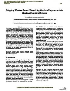
SPOT is a WSN platform that uses Java language to build applications, whose devices embody "Squawk VM" that enables running applications "on the metal" (without OS). TinyOS PSM (Fig. 1) was specified upon an extensive review of works about WSN development using such platform [1]. It includes a set of implementation characteristics not present in the DSL (as event or command creation), since these low-level features are out of scope for the application domain expert. The designed meta-model defines the basic feature of any application implemented in nesC [11] to run in TinyOS 2.x platform. In nesC, a WSN application is composed by a set of Components that can be Modules or Configurations. Modules comprise programmable parts of the executable application while Configurations are responsible for assembling Components of an application. Configurations connect declarations of different components, while Modules define functions and allocate states [14]. Components provide and use Interfaces, which contain Events and Commands. Events work as triggers to activate a desired action. Commands are functions that can be invoked to instantiate variables or assign states. Modules must implement every Command of the Interfaces they provide and every Event of Interfaces they use. Each Interface has a TypeInterface that specifies its features.
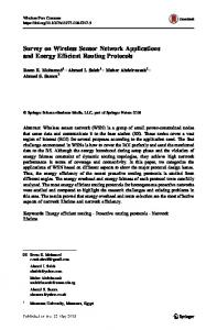
[17], a current OMG standard. To generate the PSM and source code, transformations are executed inside Eclipse environment. III. WSN APPLICATIONS DEVELOPMENT This section describes the steps required to develop a WSN application according to our proposed development process, using the artifacts provided by our MDA infrastructure. It is important to mention that all the steps take place at the design time, previously to the WSN nodes deployment. Moreover, the executable artifacts generated by our MDA process are standard code, compliant to the chosen sensor platform; it does not have any additional construct that could incur in overhead for the resource constrained sensor nodes. The first activity of the UML activity diagram illustrated in Fig. 2, “Requirements Analysis”, is performed by both the domain and the network experts, where they get all information needed to build the application. The software artifacts produced as outcome of this activity (UML diagrams as Use Cases, textual documents, etc) represent the system requirements and compose the CIM, which will be used in further phases for both developers (domain and network experts) involved in the WSN application built. The requirements document includes functional (related to the application logic) and non-functional requirements (related to the configuration of the WSN platform) and it is used by the domain expert in the “Model application with DSL” activity, to specify the PIM model (using the proposed DSL), as well as by the network expert in the “Choosing Platform” activity, where he/she evaluates the available platforms and chooses the one that best meets the elicited requirements. Following, the “Apply transformation M2M” activity is performed by the MDA infrastructure. Such activity takes as input the PIM model (generated in the “Model application with DSL” activity), with its associated meta-model, and the PSM meta-model of the WSN platform chosen by the network expert. It generates as output a PSM instance that represents the realization of the application in the chosen WSN platform. Such PSM is refined by the network expert in the “Refine Model” activity to augment the model with information about network specificities related to the target WSN platform. Finally, “Apply M2T Transformation” activity is accomplished. This activity takes as input the PSM model refined by the network expert and the transformation code concerning the chosen WSN platform and generates as output the application source code to be deployed in the sensor nodes. The generated code is then refined by both the network and the domain experts (each one regarding his specific knowledge) in “Refine Code” activity, to add improvements as application specific functions or protocol parameters that are not automatically generated by the MDA process.
Fig. 1. TinyOS/nesC PSM.
For each sensor platform existent in our MDA infrastructure, there is a set of Model to Model (M2M) and Model to Text (M2T) transformations. The M2M transformations are responsible for mapping DSL elements into elements of a given PSM. We use OMG QVTO [18] (Operational QVT Language) model transformation language to built the transformation programs. To build M2T transformation programs, code templates for each target implementation platform were defined. Two M2M transformations (DSL to TinyOS; DSL to SUNSpot) and two M2T transformations (TinyOS to nesC and SUNSpot to java) are currently available in our MDA infrastructure. M2Ts were developed using Eclipse Acceleo plugin. Acceleo is an implementation of MOF Model to Text transformation language (MOFM2T)
13
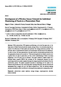
in [5]), sensors collect acceleration signals and send them to the sink node. Then, the sink node sends all gathered information to a computer that applies a set of functions to compute the current signature of the structure and compare it with the healthy signature. Data collection stages occur periodically and whenever some potential abnormality is detected in the monitored structure, the sink node issues a warning so that measures can be taken. 1) Modelling the SHM application with the DSL According to the proposed process, the first activity aims to generate the MDA CIM. Since this step can be done employing any of the existent requirements engineering approaches, we do not detail such activity. Next, the domain expert starts the application modeling using the provided DSL and the generated CIM. As a parallel activity, the network expert analyses the CIM and chooses which sensor platform will best fit the requirements of the target application. In our example, the chosen platform is MICAz MPR2400 nodes [7] running TinyOS 2.x, operating with IEEE 802.15.4 radio and energy supplied by 2 AA batteries, associated to MTS 310 sensor boards endowed with a 2-axis accelerometer. The sink node hardware is the same as the sensor nodes, although disconnected of a sensor board and connected through an USB to a PC, using a MIB 520 gateway. The PC will receive the data and compute the damage detection algorithm. There is also a shaker type actuator to force vibrations. The application modeling is done as follows. The WSN logical topology was set as flat and the data delivery model as periodic. Two Regions were created to model the SHM application. The first Region (called downtier) represents the WSN setting on one of the building floors (if there were more floors the model would be almost the same as defined for downtier Region). Inside the downtier region a NodeGroup (named Damagedetection-1) is defined with 30 sensor nodes that have as function to collect (acceleration) data of one the building floors. Besides the basic functionality of data collection defined for this group of nodes, a further (non-functional) requirement was defined representing a QoS parameter. SHM applications require periodical monitoring for as long as possible, thus demanding a long operational lifetime for the WSN. Therefore, the developer sets a low duty cycle for the sensor radios, provided that the required data sending rate is assured. The second defined Region (uptier) has a NodeGroup (named SinkNode and containing only the sink) with the goal to receive data sent by nodes in the sensing region (downtier) and with a connection to the external computer responsible to perform the damage detection calculation. A WirelessLink connects these two Regions thus representing the communication between them. The application behavior is similar to a state machine. Fig. 3 depicts a UML activity diagram representing the behavior of the application that runs into the sensor nodes (downtier Region) as a set of FunctionalUnits:
Fig. 2. Proposed MDA process to develop WSN applications
IV. EVALUATION We conducted an evaluation to determine if the proposed process and infrastructure meet our stated goals and also to assess the complexity and benefits of using our approach when compared to traditional methods to build WSN applications. We defined the objectives of the evaluation using the template of Goal/Question/Metrics (GQM) method [3] as suggested by [13]. In Sections IV.A and IV.B. we describe application development scenarios used with two purposes: (i) to illustrate the steps to build WSN applications using our approach; and (ii) to extract values for the metrics defined in our GQM. A. Illustrative Example Our example consists of a base scenario and four scenarios of changes that are used to provide answers and values for the metrics adopted in our GQM-based assessment. As base scenario, we consider the development of an application for the domain of Smart Buildings. The availability of low-power sensors will make Structural Health Monitoring (SHM) successful in future Smart Buildings. The focus of SHM applications is to detect and localize damages in civil structures [5]. All structures react to vibrations, either forced or caused by the environment. In this example, we consider a damage detection application, whose goal is to detect the presence of damage in a building using (i) accelerometers to collect vibration data (forced by actuators) in the structure, and (ii) an external computer to process the sensing data and determine the existence of structural damages. In our scenario, thirty nodes are displaced in each floor of the building to get data needed to detect any abnormality. In a first stage, sensors collect the accelerometers data of the monitored structure and send this information to the sink node connected to a computer. Such initial reading consists of the response of a “healthy” structure and is used to compare with further sensors measurements. In a following stage (called a data collection stage, as detailed
14
START_SENSING starts up the node to act as sensor; CONFIG_RADIO sets the radio duty cycle; LEDS activates a led to interact with the user and signalize application state; USER_DEFINED creates applicationspecific functions (sensor calibration in the example); TIMER sets countdowns to read, send and other activities; SEND_ACTION triggers actuators to generate artificial vibrations in the structure; READ_SENSOR_DATA reads values gathered by accelerometers; CALCULATE_ EXPRESSION computes the average of sensed data; SEND_MSG_RADIO sends accelerometers data to the sink. The application control flow is modeled by UnitLinks, represented by the transitions, with the sequential calls. Some ResourceLinks are used to connect FunctionalUnits to external devices in order to send (to the serial port in the computer) or collect (from the sensor boards) data. In the uptier Region a DataDeliveryUnit was added to receive data and a ResourceLink was added to send such data to a computer port to process them.
It is worth noting that such task needs knowledge of WSN protocols and sensor platforms that are not commonly part of the expertise of application domain developers. After concluding this activity, we have a Refined PSM containing the information to generate functional source code. Next, the activity “M2T Transformation” is performed having as input code templates for the chosen platform and the refined PSM. This transformation generates all files needed to compile the application (Configurations and Modules). Examples of the code generated by M2T transformations can be found in [1]. B. Scenarios of Change In this subsection we show four changing scenarios (denotes as SC), which represent typical situations in WSN environments: (i) change the communication protocol adopted in the network, (ii) change application requirements, (iii) a new application running in the same WSN platform; and (iv) the same application running in a different sensor platform. These scenarios, along with the example described in Section IV A., are used in the assessment of our approach. SC1: Changing Network-level Protocols. A changing in the network logic topology or in the deployed nodes density (caused by energy depletion, for instance) may require the selection of a new protocol to run on sensor nodes. By using our proposal, to meet such need the network expert has to change the generated PSM during the activity "Refine Model." For TinyOS, to modify the protocol in use the automatically generated configuration needs to be changed in 3 phases: (i) removal of “Components” that are declared, but that will not be used anymore; (ii) addition of new “Components” that implement the new protocol, and (iii) remake of “Wirings” of the “Components” reconnecting the “Interface” that is being “Used” with the new implementation “Provided” by the added “Components”. This scenario illustrates that, whenever the required change only regards network aspects, all the domain related aspects remain unchanged and are transparent to the network expert. Moreover, such changes are performed without the participation of the domain expert. SC2: Changing Application-specific Requirements. Such changes are to be handled by the domain expert and demand modifications at the PIM level. A typical case is the change in application QoS parameters. For the SHM application, if during the monitoring and analysis of data a situation of potential damage in a structure is detected, it becomes more relevant to have a rapid response that triggers required actions instead of increasing the network lifetime. This requirement can be translated into a change in the adopted energy policy and also in the value of the data transmission rate. To change the energy policy, the domain expert modifies the value of the RadioConfigUnit DSL element, which denotes the duty cycle for the nodes. To change the data transmission rate, the domain expert
Fig. 3. Behavior element Collects_building_data.
2) Generating the PSM and the Source Code The PSM and source code are generated by the M2M and M2T transformations available in our MDA infrastructure. For this scenario we used the DSL-totinyOS and the tinyOS-to-nesC transformations. Once the M2M transformation is executed, the network expert initiates the activity “Refine Model”, to add elements to the PSM not included in the DSL. For example, the network expert chooses a specific routing protocol that best fits the network topology. We leverage the MDA automatic code generation feature by designing powerful transformations that include, in the code to be deployed in the nodes, several low-level components considered either as default for that platform or very commonly adopted. Therefore, whenever the target platform is TinyOS, if the topology chosen for the network is flat, our transformation program automatically includes the components of the TOSBeaconing [21] for the routing protocol; for hierarchical topologies the components of Collection Tree Protocol [21] are included. However, the network expert may want to change the default protocol choice and during the phase of “Refine Model” he/she can set another one to be used in the WSN. To do so, the network expert changes the generated PSM as follows: (i) import the models that contain the elements representing the desired protocols, (ii) create new Wiring elements connecting the protocol Components to the Components already included in the PSM, (iii) modify the existent Configuration element including the new Wiring elements.
15
simply changes the value of the TimerUnit timer that controls the waiting time before each data transmission. In this way, the M2M transformation will generate the PSM model using settings that match the choice made by the domain expert. All of these changes can be done without requiring the participation of the network expert. SC3: Changing WSN Application. This scenario illustrates artifacts reuse at the platform level, achieved when a brand new application is created to run in a platform that was previously specified in the MDA infrastructure. A new example of application from the domain of environmental disaster monitoring (fire detection) is considered in this scenario. 50 nodes are deployed, divided into two groups: in the first, with 49 sensor nodes endowed with temperature sensing devices, the nodes were distributed through the forest to collect data and send them to a sink; in the second group the sink node receives the data collected by sensor nodes and send them to an external computer via USB link. For this example, we created two regions to represent the target (sensed) area and the sink area. For the target area we added a Nodegroup with a Behavior consisting in getting the temperature data and send to the sink. For the sink area we added another NodeGroup whose goal was to receive sensor data and send to a PC, which issues an alert whenever a potential fire is detected. After concluding all steps shown in Fig. 3, the result is the source code for a new application, produced by the reuse of several software artifacts provided by our MDA infrastructure. This scenario shows that, with the proposed approach it is possible to build different applications, from several domains, reusing all the MDA artifacts defined for a given sensor platform. SC4: Changing the WSN Platform. This scenario illustrates how the proposal promotes the reuse of the application specification and thus of all the encompassed knowledge at the application level, whenever the underlying platform changes. We assumed that the first choice of sensor platform for the SHM application was TinyOS 2.x; latter the same application is to be deployed in Sun SPOTs. Since the hardware platform, OS and programming language are different, without using our approach the entire application code would need to be programmed from the scratch. By using it, the only required steps are selecting the M2M transformation that translates from the DSL to Sun SPOT PSM to create a Sun SPOT application model, performing any required refinement in the generated model and then applying the M2T transformation (and refine the generated code). In this scenario we consider the use of Sun SPOT MPR 2400 nodes as sensor platform, running J2ME, operating with IEEE 802.15.4 radio, associated to sensor boards with a 3axis accelerometer. The sink node hardware is the same of the sensor nodes, but disconnected of a sensor board and connected, through a USB port to a PC.
C. Assessment based on Goal, Question and Metrics Considering the aims of our work and following GQM method, we first defined our primary research goals. Then, we refined the goals in a set of questions. Finally, we defined metrics that provide the grounding to answer the questions. First Goal: To analyze the proposed process/infrastructure for the purpose of evaluating their effectiveness with respect to the ease-of-development and quality of the generated code in the context of WSN applications. Second Goal: To analyze the proposed process/infrastructure for the purpose of evaluating their effectiveness with respect to the reuse of artifacts in the context of WSN applications. The following questions are considered in the evaluation. Questions Q1–Q5 are related to the first goal while question Q6 refines the second research goal. Q1: How complete is the code automatically generated by the infrastructure? Q2: How functional (in terms of the results of unit tests) is the code automatically generated by the infrastructure? Q3: How effective is the process and infrastructure to facilitate the development of WSN applications when compared to traditional approaches? Q4: How effective is the proposed process to promote the separation of concerns between application-level and network-level requirements? Q5: How expressive is the proposed DSL to specify different types of WSN applications? Q6: How effective are the proposed process and infrastructure to promote the reuse of software artifacts? 1) Metrics Since there is no standardized set of metrics available to evaluate the defined research questions, we specified our own metrics tailored to the purpose of our evaluation. Following we describe each metric, denoted Mij, where i corresponds to the question identifier, and j is a counter when there are more than one metric per question. M11: Percentage of automatically generated lines of code. An executable WSN application is a single image file embodying the application logic (algorithms to process the sensor-generated data), the sensing task description (including information to configure the network, energy policies for individual nodes, data delivery model, etc), network protocols, and the OS code (whenever it is present). In the described scenarios, we consider that the network protocols and processing algorithms are available as reusable third party libraries and that the effort to build the application lays in specifying the sensing task. However, it is important to note that even application algorithms could be partially modeled (and then automatically generated) by using the DSL, since several of these algorithms include common mathematical and aggregation functions provided as FunctionalUnits. Metric M11 was evaluated using the
16
platforms, and avoiding the need to learn each one of the libraries available for the target platforms.
SHM scenario and all four scenarios of change. The results shown that, for both the Sun SPOT and the TinyOS platforms, the MDA infrastructure succeeded in generating (M11=) 100% of the application code (further details can be seen in [1]). M21: Number of errors. To evaluate if the generated source code is free of bugs and in compliance to its required functionality, we performed unit testing with 100% of path coverage. The tests were realized for the SHM application using the code generated for the TinyOS platform inside the TinyOS simulator, TOSSIM [21]. The path coverage reports whether each of the possible paths a unique sequence of branches from the function entry to the exit - in each function have been followed. The unit tests did not report any error (M21 =0) in the generated code. This result means that the code is correct and functional. Since the goal of the tests was to evaluate the automatically generated code, the tested code was the one generated before the activity “Refine code”. M31: Reduction in the development effort. Data to assess M31 was collected through a set of experiments using as subjects computer science students. The subjects were assigned the task of developing a set of WSN applications. The subjects were divided into two teams: the first one used our MDA approach and the second a traditional WSN programming approach. Both teams had the same experience level in basic programming. The first team had no previous knowledge of MDA and DSL neither they have knowledge on TinyOS/nesC, SunSPOT/J2ME. The second team had intermediary knowledge of TinyOS/nesC acquired during one month as part of a WSN course. The experiment started with the explanation of the application requirements for both teams followed by an explanation of the MDA process. After that, a 2 hours training on the DSL was given to the first team. Each team developed 4 applications: the SHM described in this paper and 3 others [1]. The applications were developed for TinyOS since its programming model has a lower abstraction level compared to Java. All applications had the same complexity level regarding the sensing task, but different complexity regarding the specific processing algorithms. The experiment results (Table 1) show that the first team successfully completed the development of all applications in much shorter time than the second team, even without any knowledge on WSN platforms (min(M31)=8.33 and max(M31)=20.83). Therefore, the experiment demonstrates the significant reduction in the programming effort achieved with our MDA process. For instance, M31 results show that the development time to build the SHM application with the MDA infrastructure was only 8.33% of the time required using the traditional programming. Besides, when compared to manual programming of WSN application, our approach offers advantages since it handles various specific features of WSNs, unburdening the domain specialist of learning low-level details about sensor
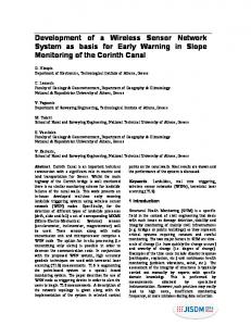
TABLE 1. M31=(DE1/DE2)*100, WHERE DE1= DEVELOPMENT EFFORT (TIME) OF TEAM 1 AND DE2= DEVELOPMENT EFFORT (TIME) OF TEAM 2. Application SHM Blink leds Basic dissemination Leds counter
DE1 45 min 30 min 35 min 25 min
DE2 540 min 180 min 180 min 120 min
M31 08.33% 16.66% 19.44% 20.83%
M41: Separation of concerns. M41 is defined by the equation (Ea - Edx)/Ea where, Ea = number of modified elements (including DSL, PSM, or code artifact) in a given change scenario and Edx = number of modified elements which are from the domain of knowledge of expert x, where x = {network, application}. The data to calculate M41 was gathered from the first and second scenarios of change. The first scenario modifies the communication protocol from the default provided by the infrastructure to an independent implementation of LEACH protocol [12]. For such change, the network expert needs to edit the generated PSM model to remove the default communication components that were added during the transformation and replace them with the LEACH protocol components. Another change will occur at the wiring level, where the network expert should specify the connections between the PSM generated components and the new ones added to support LEACH. To reflect the changes defined in such scenario, it was necessary to modify 8 (eight) network elements. No change was necessary at the domain specific level. Therefore, M41=(8-8)/8=0, meaning full separation of concerns. The second scenario modifies the duty cycle of the sensor nodes for the SHM application. Moreover, the timer element was changed to repeat the data transmission procedures to every hour instead of every day. Such modifications should be done by the domain expert without requiring the interference of the network expert. To reflect such changes, it is necessary to modify only 2 (two) DSL elements, RadioConfigurationUnit and TimerUnit, both related to the application domain Therefore, M41=(2-2)/2=0, meaning full separation of concerns. M51: Coverage. M51 is defined as the percentage of the number of DSL elements in relation to the number of new elements (at the DSL level) needed to specify a given application. All scenarios and 3 other applications [1] were used to collect data to compute M51. The DSL proved to be expressive enough to specify all applications (M51=100%). It is important to note that the applications used to assess M51 represent different (and relevant) types of current WSN applications. M61, M62 and M63: Reuse Level, at PIM, PSM, and transformation levels, respectively. These metrics compute the reuse level as defined by Frakes and Terry [10]. M61 computes the number of PIM level items
17
reused in the building of a WSN application related to the total number of PIM items. M62 and M63 have the same computation but consider the reuse of PSM elements and transformation templates, respectively. All reuse metrics were calculated using data collected from all scenarios as well the applications described in [1]. Since all the elements used to build all the applications were reused from the artifacts already embodied in the MDA infrastructure, M61, M62, and M63 = 100%.
considering the different expertise of developers for such environment. VI. FINAL REMARKS We shown how a model-driven approach may play an important role in the WSN application development by (i) increasing the abstraction level and enabling the automatic generation of the majority of application code, (ii) increasing the reuse of both domain and network expert knowledge. Besides, building WSN systems using our approach allows the division of responsibilities among developers, allowing them to use their specific knowledge and avoiding the need of learning about requirements that do not belong to their expertise field.
V. RELATED WORK In [2] Baobab is presented, a metamodeling framework to design WSN applications and generate the corresponding code. Baobab allows users to define functional and non-functional aspects of a system separately as software models, validate them and generate code. Differently from such works, our proposal was designed to allow the WSN application development without needing specific and low level knowledge on WSN platforms. In addition, our proposal deals with more than one platform. [4] presents an approach using a component-based DSLs and template-based code generators to generate an application specific middleware and increase reuse. The WSN application is interpreted as a set of components that interact via an event-based push model. The transformation of the model into executable code and the generation of the middleware are done by a template-based code generator. We do not adopt a component-based solution and it was designed to be extended by using a meta-model based approach. Moreover, they do not address the separation of responsibilities between the different types of developers involved in WSN application building. In [15] is presented a MDE approach to WSN application development. Three levels of abstraction were defined allowing designers to build: domain-specific models, component-based architecture descriptions and platformspecific models. Automatic model transformations between these three abstraction levels were designed and, to demonstrate the viability of the proposal, they developed a WSN application for irrigation control. Although this proposal is similar to ours in the sense of using transformations between models, it does not explore the generation of PSMs for different platforms nor demonstrate the behavior of the approach for different domains. We also provided an extension of the DSL presented in [15] to encompass many unavailable features. The work in [20] provides a MDE solution which supports the entire development life cycle of general purpose applications. This solution offers a NesC plug-in, which provides a graphical modeling tool and automatic for NesC code generation. Using general-purpose artifacts “adapted” to the WSN domain, WSN applications can be modeled at high abstraction level. Instead of using generic artifacts adapted to the WSN reality, we developed a solution specifically tailored to the WSN environment,
ACKNOWLEDGMENT This work was partly supported by: CNPq processes 4781174/2010-1 and 309270/2009-0 for Luci Pirmez; 306938/2008-1 and 477229/2009-3 for Flávia C. Delicato; and 311515/2009-6 and 480359/2009-1 for Paulo F. Pires. REFERENCES [1] A Model-based Approach for Building Wireless Sensor Network Applications, http://labdist.dimap.ufrn.br/twiki/bin/view/LabDistProjects/WSN. [2] Akbal-Delibas, B., Boonma, P., Suzuki, J.: Extensible and Precise Modeling for Wireless Sensor Networks. UNISCON 2009. [3] Basili, V., Caldiera, G., Rombach, H.: The goal question metric approach. Encycl Softw Eng 1:528–532 (1994) [4] Buckl, C., et al.: Generating a Tailored Middleware for Wireless Sensor Network Applications. In: IEEE SUTC 2008. [5] Chintalapudi, K., et al.: Structural Damage Detection and Localization Using NetSHM. In: ISPN 2006, 475--482 (2006). [6] Crossbow Tecnology products, http://www.xbow.com/Products/wproductsovervie w.aspx [7] Crossbow. MICAz DataSheet. Document Part Number: 60200060-04 Rev, http://www. xbow.com [8] Deursen, A., Klint, P., Visser, J.: Domain-specific languages. In: ACM SIGPAN, 26-- 36 (2000). [9] Eclipse Modeling Framework, http://www.eclipse.org/modeling/emf [10] Frakes, W., Terry, C., Software Reuse and Reusability Metrics and Models, 1995 [11] Gray, D., Levis, P., Behren, R.: The nesC Language: A Holistic Approach to Networked Embedded Systems. In: ACM SIGPLAN. 1--11 (2003). [12] Heinzelman, W. et al.: Energy-Efficient Communication Protocols for Wireless Microsensor Networks, In: Hawaaian Int'l Conf. on Systems Science, January 2000. [13] Jedlitschka, A., Pfahl, D.: Reporting guidelines for controlled experiments in software engineering. In: International symposium on empirical software engineering, p 10 (2005). [14] Levis, P.: TinyOS Programming, http://www.tinyos.net/tinyos2.x/doc/pdf/tinyos-program ming.pdf [15] Losilla, F.; et al.: Wireless Sensor Network Application Development: An Architecture-Centric MDE Approach. In: ECSA 2007, LNCS vol. 4758, pp. 179--194 (2007). [16] Model Driven Architecture, http://www.omg.org/mda/. [17] M2T, http://www.eclipse.org/modeling/m2t/?project=acceleo [18] QVTo, http://www.eclipse.org/m2m/qvto/ doc/ [19] Sun SPOT World, http://www.sunspotworld.com. [20] The Cadena 2.0 Project: Kansas State University, USA, http://cadena.projects.cis.ksu.edu/ [21] TinyOS Community Forum, http://www.TinyOS.net.
18