puter-aided software engineering (CASE), which focused ... Model-driven
engineering technologies offer a promising approach to address the inability.
G U E S T E D I T O R ’ S I N T R O D U C T I O N
ModelDriven Engineering Douglas C. Schmidt Vanderbilt University
Model-driven engineering technologies offer a promising approach to address the inability of third-generation languages to alleviate the complexity of platforms and express domain concepts effectively.
O
ver the past five decades, software researchers and developers have been creating abstractions that help them program in terms of their design intent rather than the underlying computing environment—for example, CPU, memory, and network devices—and shield them from the complexities of these environments. From the early days of computing, these abstractions included both language and platform technologies. For example, early programming languages, such as assembly and Fortran, shielded developers from complexities of programming with machine code. Likewise, early operating system platforms, such as OS/360 and Unix, shielded developers from complexities of programming directly to hardware. Although these early languages and platforms raised the level of abstraction, they still had a distinct “computing-oriented” focus. In particular, they provided abstractions of the solution space—that is, the domain of computing technologies themselves—rather than abstractions of the problem space that express designs in terms of concepts in application domains, such as telecom, aerospace, healthcare, insurance, and biology.
LESSONS FROM COMPUTER-AIDED SOFTWARE ENGINEERING Various past efforts have created technologies that further elevated the level of abstraction used to develop software. 0018-9162/06/$20.00 © 2006 IEEE
One prominent effort begun in the 1980s was computer-aided software engineering (CASE), which focused on developing software methods and tools that enabled developers to express their designs in terms of generalpurpose graphical programming representations, such as state machines, structure diagrams, and dataflow diagrams. One goal of CASE was to enable more thorough analysis of graphical programs that incur less complexity than conventional general-purpose programming languages—for example, by avoiding memory corruption and leaks associated with languages like C. Another goal was to synthesize implementation artifacts from graphical representations to reduce the effort of manually coding, debugging, and porting programs. Although CASE attracted considerable attention in the research and trade literature, it wasn’t widely adopted in practice. One problem it faced was that the general-purpose graphical language representations for writing programs in CASE tools mapped poorly onto the underlying platforms, which were largely single-node operating systems—such as DOS, OS/2, or Windows— that lacked support for important quality-of-service (QoS) properties, such as transparent distribution, fault tolerance, and security. The amount and complexity of generated code needed to compensate for the paucity of the underlying platforms was beyond the grasp of translation technologies available at the time, which made it hard to develop, debug, and evolve CASE tools and applications created with these tools.
Published by the IEEE Computer Society
February 2006
25
Another problem with CASE was its inability to scale to methods with many intricate dependencies and subtle handle complex, production-scale systems in a broad side effects that require considerable effort to program range of application domains. In general, CASE tools did and tune properly. Moreover, since these platforms often not support concurrent engineering, so they were limited evolve rapidly—and new platforms appear regularly— to programs written by a single person or by a team that developers expend considerable effort manually porting serialized their access to files used by these tools. Moreover, application code to different platforms or newer versions due to a lack of powerful common middleware platforms, of the same platform. CASE tools targeted proprietary execution environments, A related problem is that most application and platwhich made it hard to integrate the code they generated form code is still written and maintained manually using with other software language and third-generation languages, which platform technologies. CASE tools incurs excessive time and effort— The lack of an integrated also didn’t support many application particularly for key integrationdomains effectively because their related activities, such as system view often forces developers “one-size-fits-all” graphical represendeployment, configuration, and qualto implement suboptimal tations were too generic and noncusity assurance. For example, it is hard solutions. tomizable. to write Java or C# code that As a result, CASE had relatively litcorrectly and optimally deploys tle impact on commercial software large-scale distributed systems with development during the 1980s and 1990s, focusing pri- hundreds or thousands of interconnected software commarily on a few domains, such as telecom call processing, ponents. Even using newer notations, such as XMLthat mapped nicely onto state machine representations. based deployment descriptors popular with component To the extent that CASE tools were applied in practice, and service-oriented architecture middleware platforms, they were limited largely to a subset of tools that enabled is fraught with complexity. Much of this complexity designers to draw diagrams of software architectures and stems from the semantic gap between the design intent— document design decisions, which programmers then used for example, “deploy components 1-50 onto nodes A-G to help guide the creation and evolution of their hand- and components 51-100 onto nodes H-N in accordance crafted implementations. Since there was no direct rela- with system resource requirements and availability”— tionship between the diagrams and the implementations, and the expression of this intent in thousands of lines of however, developers tended not to put much stock in the handcrafted XML whose visually dense syntax conveys accuracy of the diagrams since they were rarely in sync neither domain semantics nor design intent. Due to these types of problems, the software induswith the code during later stages of projects. try is reaching a complexity ceiling where next-generation platform technologies, such as Web services and CURRENT PLATFORM AND LANGUAGE LIMITATIONS product-line architectures, have become so complex that Advances in languages and platforms during the past developers spend years mastering—and wrestling two decades have raised the level of software abstrac- with—platform APIs and usage patterns, and are often tions available to developers, thereby alleviating one familiar with only a subset of the platforms they use regimpediment to earlier CASE efforts. For example, devel- ularly. Moreover, third-generation languages require opers today typically use more expressive object-ori- developers to pay such close attention to numerous tacented languages, such as C++, Java, or C#, rather than tical imperative programming details that they often Fortran or C. Likewise, today’s reusable class libraries can’t focus on strategic architectural issues such as sysand application framework platforms minimize the need tem-wide correctness and performance. to reinvent common and domain-specific middleware These fragmented views make it hard for developers services, such as transactions, discovery, fault tolerance, to know which portions of their applications are susevent notification, security, and distributed resource ceptible to side effects arising from changes to user management. Due to the maturation of third-generation requirements and language/platform environments. The languages and reusable platforms, therefore, software lack of an integrated view—coupled with the danger of developers are now better equipped to shield themselves unforeseen side effects—often forces developers to from complexities associated with creating applications implement suboptimal solutions that unnecessarily duplicate code, violate key architectural principles, and using earlier technologies. Despite these advances, several vexing problems re- complicate system evolution and quality assurance. main. At the heart of these problems is the growth of platform complexity, which has evolved faster than the MODEL-DRIVEN ENGINEERING ability of general-purpose languages to mask it. For A promising approach to address platform complexexample, popular middleware platforms, such as J2EE, ity—and the inability of third-generation languages to .NET, and CORBA, contain thousands of classes and alleviate this complexity and express domain concepts 26
Computer
effectively—is to develop Model-Driven Engineering (MDE) technologies that combine the following:
works, rather than lower-level OS APIs. As a result, it’s often much easier to develop, debug, and evolve MDE tools and applications created with these tools.
• Domain-specific modeling languages whose type systems formalize the application structure, behavior, IN THIS ISSUE and requirements within particular domains, such This special issue of Computer contains four artias software-defined radios, avionics mission com- cles that describe the results from recent R&D efforts puting, online financial services, warehouse man- that represent the new generation of MDE tools and agement, or even the domain of environments. middleware platforms. DSMLs Two of these articles focus on the MDE tools impose domainare described using metamodels, pressing need for creating languages which define the relationships that help reduce the complexity of specific constraints and among concepts in a domain developing and using modern perform model checking that and precisely specify the key platforms. “Developing Applications can detect and prevent many semantics and constraints assoUsing Model-Driven Design Enciated with these domain convironments” by Krishnakumar errors early in the life cycle. cepts. Developers use DSMLs to Balasubramanian and colleagues build applications using eledescribes several DSMLs that simplify ments of the type system captured by metamodels and automate many activities associated with developand express design intent declaratively rather than ing, optimizing, deploying, and verifying componentimperatively. based distributed real-time and embedded systems. • Transformation engines and generators that analyze “CALM and Cadena: Metamodeling for Componentcertain aspects of models and then synthesize vari- Based Product-Line Development” by Adam Childs and ous types of artifacts, such as source code, simula- colleagues presents an MDE framework that uses tion inputs, XML deployment descriptions, or extended type systems to capture component-based alternative model representations. The ability to syn- software product-line architectures and arrange those thesize artifacts from models helps ensure the con- architectures into hierarchies to transform platformsistency between application implementations and independent models into platform-specific models. When developers apply MDE tools to model largeanalysis information associated with functional and scale systems containing thousands of elements, they QoS requirements captured by models. This automust be able to examine various design alternatives mated transformation process is often referred to as quickly and evaluate the many diverse configuration “correct-by-construction,” as opposed to convenpossibilities available to them. “Automating Change tional handcrafted “construct-by-correction” softEvolution in Model-Driven Engineering” by Jeff Gray ware development processes that are tedious and and colleagues describes a model transformation engine error prone. for exploring and manipulating large models. The Existing and emerging MDE technologies apply authors present a solution that considers issues of scallessons learned from earlier efforts at developing higher- ability in MDE (such as scaling a base model of a senlevel platform and language abstractions. For example, sor network to thousands of sensors) and applies an instead of general-purpose notations that rarely express aspect-oriented approach to modeling crosscutting conapplication domain concepts and design intent, DSMLs cerns (such as a flight data recorder policy that spans can be tailored via metamodeling to precisely match the multiple avionics components). domain’s semantics and syntax. Having graphic eleAs MDE tools cross the chasm from early adopters to ments that relate directly to a familiar domain not only mainstream software developers, a key challenge is to helps flatten learning curves but also helps a broader define useful standards that enable tools and models to range of subject matter experts, such as system engineers work together portably and effectively. In “Modeland experienced software architects, ensure that soft- Driven Development Using UML 2.0: Promises and Pitfalls,” Robert B. France and colleagues evaluate the ware systems meet user needs. Moreover, MDE tools impose domain-specific con- pros and cons of UML 2.0 features in terms of their straints and perform model checking that can detect and MDE support. prevent many errors early in the life cycle. In addition, Another source of information on MDE standardizasince today’s platforms have much richer functionality tion is available at the Object Management Group’s Web and QoS than those in the 1980s and 1990s, MDE tool site (http://mic.omg.org), which describes the efforts of generators need not be as complicated since they can the Model-Integrated Computing Platform Special synthesize artifacts that map onto higher-level, often Interest Group that is standardizing the results of R&D standardized, middleware platform APIs and frame- efforts funded by government agencies, such as the February 2006
27
Defense Advanced Research Projects Agency and the National Science Foundation. An example of this transition from R&D to standards is the Open Tool Integration Framework, a metamodelbased approach to MDE tool integration that defines architectural components (such as tool adapters and semantic translators) and interaction protocols for forming integrated design tool chains. Other standards, such as Query/Views/Transformations and the MetaObject Facility being defined as part of the UML-based ModelDriven Architecture OMG standard can also be useful as the basis for domain-specific MDE tools. Standards alone, however, are insufficient without
solid infrastructure support for developing and evolving MDE tools and applications. The articles in this special issue describe the application of various MDE tools, such as Eclipse from IBM and the Generic Modeling Environment from the Institute for Software Integrated Systems, to a range of commercial and R&D projects. To explore commercial adoption in more depth, a pair of sidebars, “Model-Centric Software Development” by Daniel Waddington and Patrick Lardieri and “Domain-Specific Modeling Languages for Enterprise DRE System QoS” by John M. Slaby and Steven D. Baker, summarize experiences applying MDE tools to complex command-and-con-
Model-Centric Software Development Daniel Waddington and Patrick Lardieri, Lockheed Martin Advanced Technology Laboratories The idea of using models to alleviate software complexity has been around for many years. However, researchers have largely applied models to selected elements of the development process, particularly structural and compositional aspects in the design phase and model checking and verification in the testing phase.
Integrated Modeling Approach At Lockheed Martin, we are developing a form of modeldriven engineering, which we call Model-Centric Software Development (MCSD).This is an integrated approach in which models are central to all phases of the development process. Our vision is subtly different from other software modeling efforts, such as the OMG’s Model-Driven Architecture (MDA)1 and Microsoft’s Software Factories,2 which concentrate largely on generating implementation artifacts from models. Instead, MCSD is based on the following concepts:
Problem
Designer/subject process Linear
Gather data
Analyze data
Our experience indicates that combining these concepts offers a promising direction for large-scale systems development. Formulate solution
Implement solution Solution Time
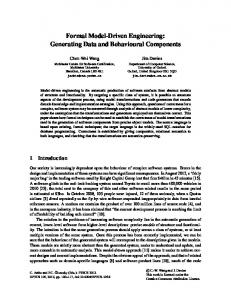
Figure A. Deviation from linear problem solving caused by wicked problems. Iterations between problem understanding and solution approaches require multiple iterations between software design, implementation, and testing.
28
Computer
• Avoiding a one-language-does-all approach. Our approach uses domain-specific modeling languages (DSMLs) to represent “aspects of interest” such as atomicity of data access, end-to-end message delay, and resource contention. • Automated generation of partial implementation artifacts. The mapping between elements in a model and corresponding elements of implementation is well defined. Rather than being restricted to program skeletons, partial implementations also can include fine-grained concrete functionality and specifications for software simulators and emulators.The models alone are not enough to build the complete implementation. • Integration of legacy assets through reverse engineering. Large-scale systems inherently require the incorporation of legacy implementation assets. Reverse engineering is used to build models (again for a given aspect of concern) from existing source code. Many previous attempts to reverse-engineer models from source code have failed due to a lack in constraining aspects of interest. • Model verification and checking. Developers can use static analysis as well as rapid-prototype generation in combination with runtime performance analysis to evaluate designs.
Addressing Wicked Problems with MCSD In our experience working on large-scale software systems, a prominent cause of inflated software development costs and extended time-to-market stems from serialized phasing, which makes it hard to evaluate design decisions until the implementation phases are complete. Developers can readily evaluate some design properties, such as interface compatibility, before the implementation is complete. However, it’s difficult to evaluate other properties, such as freedom from deadlock and scalability, without executing the software. Not being able to identify design flaws that cause such problems
trol and shipboard computing projects in large system integrator companies. The lessons learned from these types of projects help mature the MDE tool infrastructure and harden it for adoption in mainstream commercial projects. Several emerging MDE tools that bear watching in the future are the Eclipse Graphical Modeling Framework, the DSL Toolkit in Microsoft’s Visual Studio Team System, and openArchitectureWare available from SourceForge. As the articles in this special issue show, recent advances stemming from years of R&D efforts around the world have enabled the successful application of MDE to meet many needs of complex software systems.
To avoid problems with earlier CASE tools that integrated poorly with other technologies, these MDE efforts recognize that models alone are insufficient to develop complex systems. These articles therefore describe how MDE leverages, augments, and integrates other technologies, such as patterns, model checkers, third-generation and aspect-oriented languages, application frameworks, component middleware platforms, and product-line architectures. In this broader context, models and MDE tools serve as a unifying vehicle to document, analyze, and transform information systematically at many phases throughout a system’s life cycle, capturing various aspects of appli-
until late in the software development life cycle is a significant are tailoring our solution to meet specific business requirecontributor to inflated expense and delay. ments of our Information Systems and Solutions division and The problem of late-stage design evaluation in serialized its need to integrate large-scale systems for information prophasing is exacerbated in the context of large-scale systems cessing. that attempt to tackle “wicked” problems,3 in which the problem itself is not well-understood until a solution is developed. References 1. OMG,“Model Driven Architecture (MDA),” document As a result, as Figure A shows, iterations between problem ormsc/2001-07-01,Architecture Board ORMSC, July 2001. understanding and solution approaches require multiple itera2. J. Greenfield et al., Software Factories: Assembling Applications with tions between software design, implementation, and testing. Patterns, Models, Frameworks and Tools, John Wiley & Sons, 2004. To develop effective software for large-scale systems and 3. H. Rittel and M.Webber,“Dilemmas in a General Theory of systems-of-systems, Lockheed Martin is applying MCSD techPlanning,” Policy Sciences, vol. 4, no. 2, 1973, pp.155-169. nologies and processes that alleviate problems with serialized phasing. Daniel Waddington is a lead member of the engineering We are particularly interested in exploring modeling of staff at Lockheed Martin Advanced Technology Laboratories, execution architecture, and enabling system engineers to Cherry Hill, N.J. Contact him at
[email protected]. explore execution design and its effect on system dynamics; this is achieved through static analysis and rapid generation of artifacts for simulation and emulation.This approach facilitates Patrick Lardieri is manager of distributed processing programs at Lockheed Martin Advanced Technology Laboratorapid iteration between problem definition and implementaries, Cherry Hill, N.J. Contact him at
[email protected]. tion solution concerns. An important lesson that we have learned is that models should not be used to replicate the abstractions that programming languages View View View View provide. As Figure B shows, models should Abstract views abstract selected elements of the implemented complex system. Translation We do not believe it is feasible—at least in Model Model Abstraction the near term—to generate a complete implementation from models of the system alone. Furthermore, we do believe that multiple modeling notations and interpretations (views) are necessary to represent each of the Complex systems different aspects of concern and to fulfill different roles within MCSD such as verification of correctness, human understanding through visual interpretation, and code generation. Lockheed Martin is pursuing the MCSD Figure B. Relationship between views, models, and implementation. Rather than vision by integrating selected technologies in metamodeling, model checking and verification, replicating the abstractions that programming languages provide, models abstract upon “selected” elements of the implemented complex system. code generation, and reverse engineering.We
February 2006
29
cation structure, behavior, and QoS using general-purpose or domain-specific notations.
A
lthough a great deal of publicity on model-driven topics has appeared in the trade press, it’s surprisingly hard to find solid technical material on MDE technologies, applications of these technologies to complex production-scale systems, and frank assessments of MDE benefits and areas that still need attention. For example, further R&D is needed to support roundtrip concurrency engineering and synchronization between models and source code or other model representations,
improve debugging at the modeling level, ensure backward compatibility of MDE tools, standardize metamodeling environments and model interchange formats, capture design intent for arbitrary applications domains, automate the specification and synthesis of model transformations and QoS properties to simplify the evolution of models and metamodels, and certify safety properties of models in DSMLs and in their generated artifacts. Although MDE still faces some R&D challenges, decades of progress and commercialization have enabled us to reach the critical mass necessary to cross the chasm to mainstream software practitioners. The articles in this issue help replace hype with sound technical insights
Domain-Specific Modeling Languages for Enterprise DRE System QoS John M. Slaby and Steven D. Baker, Raytheon, Portsmouth, R.I. Researchers are increasingly developing enterprise systems in many domains using applications composed of distributed components running on feature-rich middleware frameworks, in what is often termed a service-oriented architecture.
SOA Middleware In SOA middleware, software components provide reusable services to a range of application domains, which are then composed into domain-specific assemblies for application (re)use. Examples of SOA middleware platforms include J2EE, .NET, and the CORBA Component Model (CCM). The transition to SOA middleware is gaining momentum in the realm of enterprise business systems because it helps address problems of inflexibility and the reinvention of core capabilities associated with prior generations of monolithic, functionally designed, and “stovepiped” legacy applications. Whereas software engineers developed legacy applications with the precise capabilities required for a specific set of requirements and operating conditions, SOA components have a range of capabilities that enable their reuse in other contexts. Moreover, enterprise systems are developed in layers consisting of infrastructure middleware services (such as naming and discovery, event and notification, security and fault tolerance) and application components that use these services in different compositions. Developers are also applying certain types of SOA-based middleware, such as real-time CCM, to the enterprise distributed real-time and embedded (DRE) systems domain, such as total-ship computing environments and supervisory control and data acquisition systems, to provide users with quality-ofservice support to process the right data in the right place at the right time over a computer grid. Some QoS properties that enterprise DRE systems require include low latency and jitter, as expected in conventional real-time and embedded systems, and high throughput, scalability, and reliability, as expected in conventional enterprise distributed systems. Achieving this combination of QoS capabilities is difficult.
30
Computer
SOA middleware can also complicate software life-cycle processes by shifting responsibility from software development engineers to other types of software engineers (such as software configuration and deployment engineers) and systems engineers. Software development engineers traditionally created entire applications in-house using top-down design methods that they could evaluate throughout the life cycle. In contrast, today, software configuration and deployment engineers and systems engineers must increasingly assemble enterprise DRE systems by customizing and composing reusable SOA components, whose combined properties they usually evaluate only during the integration phase. Unfortunately, fixing problems uncovered during integration is much more costly than if they had been discovered earlier in the life cycle.Thus, a key R&D challenge is exposing these types of issues (which often have dependencies on components that are not available until late in development) earlier in the life cycle—prior to the system integration phase. SOA-based enterprise DRE systems require design and runtime configuration steps, which customize reusable components behavior to meet QoS requirements in the context where they execute. Finding the right component configurations to meet application QoS requirements can be a daunting task. For example, tuning a DRE shipboard computing system’s concurrency configuration to support both real-time and fault-tolerant QoS involves tradeoffs that challenge even the most experienced engineers. Moreover, since application functionality is distributed over many components in an SOA, developers must interconnect and integrate components correctly and efficiently, which is tedious and error prone using conventional handcrafted configuration processes. The components assembled into an application must also be deployed on the appropriate nodes in an enterprise DRE system.This deployment process is hard since the characteristics of hosts onto which components are deployed and the networks over which they communicate can vary both statically (for example, due to different hardware/software plat-
and lessons learned from experience with complex systems. We encourage you to get involved with the MDE community and contribute your experience in future conferences, journals, and other publication venues. A summary of upcoming events and venues for learning about and sharing information on the model-driven engineering of software systems appears at www. planetmde.org. ■
Markus Völter for spirited discussions at the 2005 OOP Conference in Munich, Germany, that helped shape my thinking on the role of MDE in modern languages and platforms. I also thank Arvind S. Krishna for inspiring this special issue. Finally, thanks to the members of the MDE R&D community, who are spurring a crucial paradigm shift in generative software technologies.
Acknowledgments I thank Frank Buschmann, Jack Greenfield, Kevlin Henney, Andrey Nechypurenko, Jeff Parsons, and
Douglas C. Schmidt is associate chair of computer science and engineering and a professor of computer science at Vanderbilt University. Contact him at d.schmidt@ vanderbilt.edu.
forms used in a product-line architecture) and dynamically (for example, due to damage or faults, changes in computing objectives, or differences in the real versus expected application behavior during actual operation). Evaluating the operational characteristics of system deployments is therefore tedious and error prone, particularly when developers perform the deployments manually.
generation, data reduction, and visualization to rapidly construct experiments and comparatively analyze results from alternate execution architectures.The tools can also import measured performance data from faux application components running over actual configured and deployed infrastructure SOA middleware services to better estimate enterprise DRE system behavior in a production environment.
Solution Approach: System Execution Modeling Tools
Raytheon Experience with MDD Tools
Despite the flexibility that SOA middleware offers, surprisingly few configuration and deployment designs can satisfy an enterprise DRE system’s functional and QoS requirements. To address these challenges, Raytheon is developing system execution modeling (SEM) tools that combine QoS-enabled SOA middleware and model-driven development (MDD) technologies. Software architects, developers, and systems engineers can use these SEM tools to explore design alternatives from multiple computational and valuation perspectives at multiple life-cycle phases using multiple quality criteria with multiple stakeholders and suppliers. In addition to validating design rules and checking for design conformance, these SEM tools facilitate “what if” analysis of alternative designs to quantify the impact and costs of certain design choices on end-to-end system performance.These choices include determining the maximum number of components a host can handle before performance degrades, the average and worst response time for various workloads, and the ability of alternative system deployments and configurations to meet end-to-end QoS requirements for various workloads. In the context of enterprise DRE systems, our SEM tools help developers, systems engineers, and end users discover, measure, and rectify integration and performance problems early in the system’s life cycle—that is, during the architecture and design phases, as opposed to the integration phase, when fixing mistakes is much harder and more costly. With SEM tools, users can visually create arbitrarily complex SOA-based applications and perform experiments that systematically evaluate interactions that are hard to simulate. In particular, these tools facilitate MDD-based workload
As the basis for our system execution modeling tools, the MDD paradigm and the Generic Modeling Environment and CoSMIC MDD tools developed at the Institute for Software Integrated Systems have provided an effective core set of capabilities that we have found to be easy to extend and intuitive to use. We are currently in the process of transitioning these technologies into mainstream acquisition programs at Raytheon. Despite this promising start, however, much work remains to be done to create a unified MDD environment that supports the wide range of technologies, including currently incompatible component frameworks and legacy applications, found in enterprise DRE systems throughout all phases of the software development life cycle. These tools are still maturing, with major challenges remaining before the entire enterprise computing environment can be modeled, validated, configured, and deployed via a unified modeling interface.
John M. Slaby is a member of the DD(X) architecture team and the principal investigator for research focused on modeldriven development and domain-specific modeling languages at Raytheon Integrated Defense Systems, Portsmouth, R.I. Contact him at
[email protected]. Steven D. Baker is a software engineer on the DD(X) Weapon Control Element team and a researcher on modeldriven development and domain-specific modeling languages at Raytheon Integrated Defense Systems, Portsmouth, R.I. Contact him at
[email protected].
February 2006
31