The compiler converts the behavioural model into an intermediate format (IF) which serves as ..... systems. Spider is able to execute test cases on systems written in Java, C, or C++ running on ... Net, and the Sun initiatives NetBeans and MDR.
Model Driven Testing – AGEDIS Architecture Interfaces and Tools Alan Hartman Kenneth Nagin
IBM Haifa Research Laboratory Haifa University Campus Haifa 31905 ISRAEL {hartman, nagin}@il.ibm.com
ABSTRACT This article describes the AGEDIS project, a European Commission sponsored project for the creation of a methodology and tools for automated model driven test generation and execution for distributed systems. We describe the AGEDIS architecture, interfaces, and tools, and discuss some lessons learned over the three year life of the project.
1 Introduction
Software modeling is an area of research that has enjoyed great popularity in recent years through the widespread adoption of object-oriented models as an aid to software design [5]. The use of software models for the generation of test suites has also been reported in both an academic setting [6, 11, 13, 13, 14], and in practical experiments [4, 7, 15, 16]. However, the adoption of a specification based modeling strategy for generating test suites has yet to gain much industrial momentum. One of the reasons for this is the lack of an integrated toolset whose specific purpose the model-based generation and execution of software test. Most commercial software modeling tools (e.g. Rational XDE, Together, Telelogic Tau) are intended for the use of designers and developers of software rather than quality assurance and testing personnel. There are however, a number of academic and proprietary tools in the area of model based test generation and execution. These tools could benefit from being integrated into a framework where they could interoperate. We describe here an architecture for model based testing that was implemented in the AGEDIS project, together with its interfaces. We also describe some tools that were plugged into this architecture, and we argue for greater cooperation and standardization in this area. The results of the AGEDIS experimentation with these tools [4] indicate that we still have a long way to go before these tools are ready for widespread adoption by industry. The main outstanding issues are the usability and interoperability of the available offerings. A number of initiatives are under way to deal with these issues. Among these initiatives are the OMG standardization body, the Eclipse organization, the ModelWare initiative, and the W3C standards body. One of the aims of the ModelWare initiative is to provide European tool vendors and academics with an infrastructure to support integration and interoperability of all model driven software engineering tools. The AGEDIS project has taken a first step along the way by defining clear interfaces between tools in the model based testing arena. It is the aim of this presentation to publicize these interfaces, point out their interrelationships with other initiatives, and point the way forward to standards based integration with other tools in the wider area of model driven software engineering.
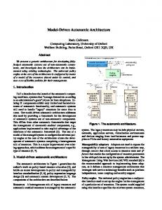
2 Architecture Simulator Behavior Model
Compiler
Execution Interface
Generator
Generation Directives Abstract Test Suite
Analyzers
User Interface
Edit/Browser Execution Directives
SW Component
Execution Engine Execution Trace
User Input
Public Interface
The AGEDIS architecture is designed for open participation and interchangeable software components to be developed and implemented as necessary. For example, we welcome the idea that other academic groups adapt their experimental test generators to the interfaces described here so that they may take advantage of the AGEDIS execution engine, test analyzers, and visualizers. We also would like to encourage other analysis tools to be fitted to the interfaces to enable the users to benefit from the increased power. We recognize that no one modeling language will be adequate to express all software models from all domains. Some groups in the telecommunications industry use SDL to model software, and case studies have been reported using Z, CSP, UML, Murphi, SPIN, and others. We maintain that our architectural structure allows for a diversity of modeling languages, and the reuse of existing testing tools and execution engines. The behavioural model of the system under test is specified by the user in the AGEDIS Modelling Language (AML) [1]. Other languages have been used for behavioural modeling in this context including both Objective VHDL[17] and Murphi[8]. In an intermediate step – hidden from the user – the modeling tool, Objecteering’s UML modeler outputs an XML encoding of the model which is then read by the AGEDIS model compiler. The compiler converts the behavioural model into an intermediate format (IF) which serves as the execution interface. The test generation directives including the coverage goals of the test suite, constraints on the test suite, and specific test purposes are compiled together with the model and fed directly into the test generator. The test generation directives encapsulate the testing strategy and tactics. The execution interface can be executed either by a manual simulator or an automated test case generator. The manual simulator is used both to verify that the model behaves as its author intended it to, and also to produce additional test purposes.
The test generator produces an abstract test suite (ATS), which consists of paths and directed graphs (in the case of a non-deterministic system) through the model satisfying the coverage criteria or instantiating the test purposes. This ATS format [2] contains all the information necessary to run the tests and verify the results at each stage of each test case. The user can validate the model by viewing this suite, and use this format to communicate with the developers when a defect is discovered. The test execution directives (TED) form the bridge between the abstractions used in the behavioural model and the implementation details of the system under test. The execution engine reads the abstract test suite and the test execution directives in order to execute the test suite against the application being tested. Each stimulus for each transition is presented to the application under test. The execution engine queries the state of the application, or waits for responses sent by the application in order to verify that the application and the model agree on the results of applying the stimulus. The results of the stimulus and verification are written to a suite execution trace (SET - also specified in [2]) in a standard form accessible to all existing and future productivity tools including the analyzer and visualizer. The visualizer is capable of showing both the suite execution trace and the abstract test suite in a visually informative way to enable the test engineer to comprehend the massive amounts of data generated by automated test generation and execution. The coverage analyzer reads the execution trace and identifies areas of the model that may not have been covered sufficiently. It is intended to produce input for the test generator to provide additional test cases. This feedback to the test generator is important in real situations where the translation from abstract tests to actual test runs may not be completely accurate. The defect analyzer also produces input to the test generator. Its function is to cluster the defects observed and to try and reproduce each defect cluster with a simpler test case. The user interface can invoke editors for the models, test directives, and execution directives. It also invokes the tools and manages the files and other artifacts produced by the automated testing process.
3 Interfaces
The main interfaces in the AGEDIS architecture are the following: Behavioural modeling language Test Generation Directives Test Execution Directives Model Execution Interface Abstract Test Suite Test Suite Trace The first three interfaces are for the users’ primary access to the tools. The latter three are more for internal use by the tools, but the abstract test suite may also be directly used by a user to script a particular test case.
3.1 Behavioural Modeling Language The behavioural model describes the behaviour of the system under test. It is implemented as a UML profile. The structure of the system under test is decribed by class diagrams together with associations between classes. The behaviour of each class is described in a state diagram for that
class. The action language used in the state diagrams is the IF language. The interface between the system under test and the environment is described by attaching stereotypes or to methods and attributes of the classes. A controllable method or signal is one which the tester can call or send as a means of stimulating the system under test. Observable artifacts of the system are those which can be used by the tester to check the response of the system to the stimuli. The initial state of the system is described using an object diagram. Stereotyped object diagrams may also be used to specify particular states of the system which must be included or excluded from test cases. A full description of the syntax and semantics of the behavioural modeling language is available from the AGEDIS web site [1].
3.2 Test Generation Directives The test generation directives comprise the users’ testing strategies and tactics; they instruct the test generator how to create test suites. They are expressed as either system level state diagrams, message sequence charts, or by a set of simple defaults applied as run time parameters to the test generation engine. The state diagrams and message sequence charts use wild cards for details of the test case which are to be filled in by the test generator. The transitions used in these state diagrams represent an arbitrary sequence of transitions to be chosen by the test generator. Test purposes are not easy for many users to create – and thus the AGEDIS test generator is equipped with a set of graduated test generation directives which enable the naïve user to generate test suites of increasing complexity and with presumably increasing probabilities of exposing defects in the application. These simple test generation directives are: 1. Random test generation: Test cases are generated randomly, their length being provided by the user or randomly chosen. 2. State coverage: Test cases aim to cover all states of the specification. 3. Transition coverage: Test cases aim to cover all transitions of the specification. 4. Interface coverage: Test cases aim to cover all controllable and observable elements of the test interface. 5. Interface coverage with parameters: Test cases aim to cover all controllable and observable elements of the test interface, with all combinations of parameters.
3.3 Test Execution Directives The test execution directives describe the test architecture and the interface between the model and the system under test; they instruct the test execution engine both where and how to execute the test suites. The TED contains both model translation information and test architecture information. The model translation information comprises mappings from the abstractions of data types, classes, methods, and objects described in the model to those of the system under test. The test configuration information includes host information for distributed systems, delays and timeouts, polling intervals, prologues and epilogues for test suites, test cases, and test steps, and sets of parameters for parametrized test cases.
The test execution directives are described by an XML schema, so the user may edit the directives using any XML editor. The XML schema is available from [].
3.4 Model Execution Interface (IF) This is an encoding of the classes, objects, and finite state machines, which describe the behaviour of the system under test. The model execution interface of the AGEDIS tools is in the IF language created and extensively used by Verimag. It is a language for the description of communicating asynchronous systems with extensions to support the generation of test cases. The execution interface is documented and publicly available on the AGEDIS website [3].
3.5 Abstract Test Suite and Test Suite Trace Both the abstract test suite and suite execution trace are described by the same XML schema testSuite.xsd [2]. A test suite document consists of a set of test cases (or a reference to an external set of test cases) and zero or more test suite traces. The test suite also contains a description of the model used to create the test cases. The model is described in terms of its classes, objects, and interfaces for observability and controllability. Each test case consists of a set of test steps which may contain stimuli, observations and directions for continuation to the next step or to the reaching of a verdict. The stimuli and observations may take place between the system under test and the environment (tester), or between two observable parts of the system under test (SUT). Usually, a test interaction is initiated by the tester on a SUT object. However, SUT objects may initiate actions on the test environment or the tester may be required to observe interactions between SUT objects. These interactions may be either synchronous or asynchronous. Several actions may take place in any given test step – and these within a single step may be executed sequentially or in parallel. Each test case contains a verdict which may be one of pass, fail, or inconclusive. The latter verdict is registered when a test case runs without observable deviation from the specification, but also without achieving the purpose of the test case. The test cases can describe nondeterministic behaviour using a construct for alternative steps. Test cases can be parametrized, so that the same test case may be run several times with different values for the parameters. Test cases may also invoke other test cases as sub steps of the invoking test case. A test case may be visualized as a labeled transition system with nodes representing steps, and labels on the transitions representing the stimuli and/or responses which trigger the system to move to the target step of the transition. The design of the Abstract Test Suite (ATS) was motivated by several objectives: Expressiveness: the schema is expressive enough to describe complex test scenarios, and to provide a rich set of interactions between a test engine and a system under testing. This includes concurrent and sequential processing semantics. Simplicity: the syntax chosen to express test cases is simple. Test suites may be produced either by tools or manually. This implies that the ATS syntax is simple enough to be read, written, or modified by a human being. Flexibility: Therefore, the ATS format is flexible enough to support new features or new primitives needed by other tools.
Compatibility: AGEDIS defined a new ATS format, since the existing formats were tool dependent or too specific to a particular application domain. However, the AGEDIS ATS format is influenced by three formalisms: o The Gotcha-TCBeans ATS format o The TGV ATS format o The TTCN –3 (Tree and Tabular Combined Notation) language, standardized by the ITU-T. In the future, some translation tools may be provided between these different formats (or at least between parts of them). The suite execution trace is integrated into the abstract test suite definition. Its design was motivated by the following objectives: Expressiveness: The schema is expressive enough to capture the actual test suite execution. Most importantly, it must contain enough information to allow replay of a fault finding test scenario. Traceability: The schema allows the user to identify which abstract test suite paths are covered by the trace. Packaging Flexibility: The suite execution trace and abstract test suite may reside in the same or different files to simplify file handling and archiving. Repeatability: The trace can be used as input to repeat its execution. Feedback: The trace may be used as feedback in order to generate a new abstract test suite, or test purposes. The main motivation behind the choice of an XML schema is that this is a popular data exchange standard, with a simple definition, and for which several public parsers, browsers and editors are available.
4 Tools
4.1 User Interface The AGEDIS tools have a common graphical user interface, written as a standalone Java application, which enables the user to access all the tools and edit the inputs. The interface supports the testing workflow by structuring the user’s interaction with the AGEDIS components according to the AGEDIS methodology. That is: 1. Construct a model 2. Debug it with the IF simulator 3. Construct test generation directives 4. Generate test suites (by compiling the model together with the test generation directives) 5. Create the testing interface (test execution directives) 6. Execute the test suite 7. Analyze the test suite and test trace 8. If the coverage achieved is insufficient, or defects need to be analyzed, then use the analysis results to construct more test generation directives and repeat from step 4.
4.2 Behavior simulation The IF simulator enables the user to observe the behaviour of the model. The interface to the simulator consists of two windows, one containing the controllable aspects of the model, and the other with a message sequence chart describing the path taken through the model so far. The user chooses an action to apply to the model and observes the set of possible responses by the system. This enables the user to see the model “in action” and understand its behaviour more fully.
4.3 Test generation The test generator creates a set of test cases which satisfy the coverage criteria and test purposes specified in the test generation directives. The test generation process consists of two stages. First a labeled transition system (LTS) is constructed from the Cartesian product of the model’s behaviour and the test purposes. The LTS is traversed and a set of test cases is extracted leading from the initial state to a state where the test purpose reaches an “accept” verdict. The states also carry the observable values of variables, so that when a coverage criterion occurs in a test purpose, the test generator may produce a series of test cases passing through states where all values of the observable variables are realized. In order to deal with large models, the test generator is able to generate test cases incrementally, without unfolding the entire LTS. The details of the test generation algorithms will appear in a forthcoming paper.
4.4 Test execution The test execution framework – code named Spider for its ability to trap bugs – is an interpreter of the test suite format. The translation between the abstractions of the model and the actual implementation and deployment of the system under test is provided by the test execution directives. The primary goal of the test execution framework is to create a platform independent and language independent set of utilities for test execution, tracing and logging of distributed systems. Spider is able to execute test cases on systems written in Java, C, or C++ running on distributed platforms including heterogeneous operating systems. Spider provides the facilities for: Distributing the test objects. Generating the stimuli specified in the abstract test suite - both synchronous and asynchronous interactions, with sequential or parallel execution of concurrent stimuli. Making observations of the distributed system. Comparing those observations with the expected results in the abstract test suite. Creating a centralized log of the execution Writing a trace in the test suite XML format Passing parameters to test cases Multiplying the test objects to create stress test from function tests The details of the execution framework are described in [10].
4.5 Test analysis AGEDIS provides two analysis tools, a coverage analyzer and a defect analyzer, for generating both human and machine readable feedback to the test team.
The coverage analyzer reports on combinations of data values not covered, and sequences of methods not invoked. It outputs test purposes which direct the test generator to create test cases to cover these values and sequences. It also outputs coverage analysis reports. The coverage analysis tool reads either the test suite or the test trace. The results of the trace may provide significantly less coverage of the application since the trace only executes a deterministic part of the entire non-deterministic test suite. The defect analyzer clusters the defects observed in a test trace, and produces a single test purpose which will recreate the common features of a set of test cases resulting in an observed bug. This tool provides added value in the case when a large volume of test cases is run, with many failures, but possibly many repeated occurrences of the same fault.
5 Lessons Learnt
The initial goal of the AGEDIS project was to increase the efficiency of software testing for component based distributed applications. The industrial experiments – reported on in more detail elsewhere in this volume – show that we still have a long way to go in terms of usability, marketability, and even in the functionalities that the tools offer. Another of the main aims of the AGEDIS project is to provide an infrastructure and standard methods of communication between tools in the area of model driven testing. Since the project began three years ago, the goals of interoperability of tools have received much wider currency, and the entire area of model driven software engineering is awash now with standards and interfaces. None of these standards has become totally pervasive, with the possible exception of UML as a modeling language. But even here there are several profiles for UML which provide for a behavioural semantics. The behavioural aspects of UML 2.0 are still too new to have received tooling support and acceptance in the software engineering industry. Other standards for the area include SDL and TTCN – used by the telecommunications industry are not necessarily appropriate for standard IT applications, database, transaction processing, or web services. The Eclipse open source Modeling Framework, and the Eclipse tooling infrastructure are rapidly gaining ground as the future interoperability platform for software engineering and software integration. Although Eclipse too has its rivals for the hearts and minds of the development community in the Microsoft worlds of C# and .Net, and the Sun initiatives NetBeans and MDR.
5.1 What we would do the same? What different? If we could do it all over again with 20/20 hindsight, what would we repeat, and what would we do differently? We have tried to summarize some of the decisions taken in the following table: What would we repeat? What would we do differently? Modeling language: We based our modeling Modeling language: We chose IF as the action language on UML 1.4 with a profile for language. With 20/20 hindsight we should behavioural and testing semantics. This proved have chosen either OCL or a subset of Java to to be a wise decision in terms of industry be more in line with standards and our acceptance customer base. Modeling Tool: We chose Objecteering for its Modeling Tool: The Objecteering UML superior profile builder, and because there was modeler is no longer freely available. We a free version for our customers. would have done better to chose an open source UML modeler of lower quality.
Interface to Simulation and Test Generation: We chose an interface based on IF in order to speed the development of the test generator. Test Generation: We chose to build a test generator merging the capacities of GOTCHA and TGV. This proved difficult – but eventually will be worth the effort. Test Suite and Test Trace Format: The XML testSuite format is a great achievement of the project – and should be pushed to become a standard in the IT sector of the industry. Test Execution: The execution engine is very powerful and flexible, eliminating much repetitive effort in the foundation classes needed for test execution and logging. Test Analysis: Basing the analysis tools on the XML format for test suites and test traces gave us a lot of flexibility, and enabled rapid prototyping of new analysis tools.
Interface to Simulation and Test Generation: We should have chosen an interface based on XMI 2.0 (which was not defined 3 years ago). Test Generation: We should have provided more “instant gratification” to our customers with simpler test purposes and coverage criteria, even random test generation as an immediate “smoke test” option.
Test Execution: Provide more ready made execution maps for common testing scenarios. Test Analysis: Get more feedback earlier in the project from users as to the kinds of analysis that are relevant in industry. User Interface: Had we started this effort now – we would have chosen to integrate the AGEDIS tools in an open source IDE like Eclipse.
6 References
AGEDIS Public Document: AGEDIS Modeling Language Specification. AGEDIS Public Document: Test http://www.agedis.de/documents/d291_2/testSuite181202.zip
Suite
Specification
AGEDIS Public Document: Intermediate Language 2.0 with Test Directives Specification http://www.agedis.de/documents/d289_1/IF2.0_TD.pdf I. Craggs, T. Hierrault, M. Sardis, and J. Trost, this volume. G. Booch, Object Oriented Analysis and Design With Applications. Benjamin/Cummings, 2nd edition, 1994. J. Callahan, F. Schneider, and S. Easterbrook, Automated Software Testing Using Modelchecking, Proceedings 1996 SPIN Workshop, 1996. J. M. Clarke, Automated Test Generation From a Behavioural Model, Proceedings of the 11th International Software Quality Week, QW98, May 1998.
D. L. Dill, A. J. Drexler, A. J. Hu and C. Han Yang, Protocol Verification as a Hardware Design Aid, 1992 IEEE International Conference on Computer Design: VLSI in Computers and Processors, IEEE Computer Society, pp. 522-525. http://sprout.stanford.edu/dill/murphi.html A. Hartman and K. Nagin, TCBeans Software Test Toolkit in Proceedings of the 12th International Software Quality Week, QW99, May 1999. A. Hartman, A. Kirshin, and K. Nagin, J. Hartmann, C. Imoberdorf, and M. Meisinger, “UML-Based Integration Testing” in Proceedings of ISSTA 2000. R. M. Hierons, Testing From a Z Specification, The Journal of Software Testing, Verification, and Reliability, 7:19–33, 1997. J. Offutt and A. Abdurazik, Generating Tests from UML Specifications, Second International Conference on the Unified Modeling Language (UML99), 1999. A. J. Offutt and S. Liu, Generating Test Data from SOFL Specifications, to appear in The Journal of Systems and Software 1999, currently available from http://isse.gmu.edu/faculty/ofut/rsrch/spec.html. A. Paradkar, SALT – An Integrated Environment to Automate Generation of Function Tests for APIs, to appear in Proceedings of ISSRE 2000. R. M. Poston, Automated Testing From Object Models, Aonix White Paper July 1998, http://www.aonix.com. M. Radetzki, W. Putzke-Röming, and W. Nebel, A Unified Approach to Object-Oriented VHDL. Journal of Information Science and Engineering 14 (1998), pp. 523-545. http://eis.informatik.uni-oldenburg.de/research/request.shtml J. C. Widmaier, C. Smidts, and X. Huang, Producing More Reliable Software: Mature Software Engineering Process vs. State-of-the-Art Technology, International Conference on Software Engineering (ICSE) 2000.