4th Power Electronics,Drive Systems & Technologies Conference (PEDSTC2013),Feb 13-14,2013,Tehran,Iran
Modeling and Simulation of Dual Mechanical Port Machine Mohammad Ghanaatian
Ahmad Radan
Electrical and Computer Engineering K.N.Toosi University of Technology
Electrical and Computer Engineering K.N.Toosi University of Technology Tehran, Iran
[email protected]
Tehran, Iran
[email protected] Abstract-In this paper a new generation of electrical machine will be introduced. This type of machine consists of a stator and two rotors. It has two mechanical ports and two electrical ports. Because of the structure of this machine, it is named Dual Mechanical Port (DMP). As DMP has higher number of ports, it is more flexible and has more operation modes in comparison with previous machines. It also has some exclusivity such as existence of two air gaps and two rotational parts with dependent speed and torque. In this paper the structure of this new machine has been inspected and simulated model has been presented. Keywords- Dual Mechanical Ports, Speed, Torque, Control
I.
INTRODUCTION
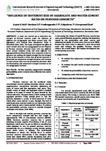
Figure I. Model ofDMP machine
Every electrical machine whether it is AC orDC is a means of energy conversion. A common type of machine in the industry is a machine with one electrical port and one mechanical port. Their perfonnance is based on injecting electrical energy from their electrical port (usually stator) and obtaining mechanical energy from their mechanical port (rotor) in motor mode operation. DMP is a new generation of electrical machine consists of a stator and two rotors. This machine has electrical ports on the stator and inner rotor and mechanical ports on both rotors. Existence of two ports made these machines more flexible and increased their performance relative to previous ones. Because of their flexibility these machines could be applied in systems such as hybrid electric vehicles [1-6], wind energy conversion systems [7] and so on. In this paper, the proposed machine has two mechanical ports and two electrical ports. The paper is organized as follows: in the second part of this paper, structure ofDMP is probed. In the third part, the dynamic model and different modes of operation of DMP is studied. Simulation results are presented in part four. Finally in the last part conclusion is presented. II.
Angular speed in one of the three parts is equal to zero and considered as stator. The two other rotational parts are considered as rotors. In this paper it is supposed that Wi is equal to zero and considered as stator. Part 2 and part 3 are outer rotor and inner rotor respectively. Fig. 2 shows these three discrete parts. The inner rotor is fed with a three-phase winding through slip rings. The stator is also fed with a three phase winding. Permanent magnets are mounted on the outer rotor.
Figure 2. Different parts ofDMP
STRUCTURE OFDMP
A rotating field is caused in the machine due to the existence of three-phase winding on the stator. As the outer rotor is a PM, it rotates synchronously with the stator rotating field like a PMSM operation. Inner rotor voltage frequency is also equal to the slip speed between the outer rotor and the inner rotor and another rotating field is caused in the machine due to the inner rotor. So the stator and the inner rotor fields rotate in the machine with the same speed.
DMP is more similar in structure to a DFIG with an extra outer rotor which makes it more flexible and controllable. In fact it is a compact machine that plays the role of two machines- inner machine consists of inner rotor and outer rotor and outer machine consists of outer rotor and stator. These two machines can function as either motor or generator. Depending on motor or generator function, different modes of operation are possible for DMP. Fig. 1 shows a typical DMP structure [8].
978-1-4673-4484-5/13/$31.00 ©2013 IEEE
If Wz > UJ3 or UJz < UJ3, in both cases there will be a slip between the rotors. Energy flow in the inner rotor is
125
In equation (3) unlike equation
proportional to slip of two rotors. Depending on the slip sign
(2)
mechanical energy of
between the two rotors, direction of power flow between the
inner rotor considered as input of the machine, also transferred
two rotors will be positive or negative [8].
energy from the stator to the battery considered as the output of the machine. The direction of inner rotor electrical power could
The rotors can be controlled by the control of stator
be positive or negative, depending on the slip sign of two
electrical port. Moreover the machine can be controlled by the
rotors. In this condition DMP act as a power combiner.
effect of external mechanical energy through mechanical ports
Because
(two rotor shafts). In the hybrid electric vehicle application,
the
mechanical
energy
of
mechanical
ports
is
combined together and appears as electrical energy in the
outer rotor of DMP is mechanically connected to the wheels
electrical port of stator and can be saved in battery. This
and inner rotor is connected to the internal combustion engine
situation
(ICE). Electrical ports also have a sharedDC link (battery).
can
deceleration.
be
occurred
Consequently
in
the
hybrid
mechanical
vehicles energy
during of
the
vehicle and ICE will be saved in the battery.
DMP machine is made in three forms namely radial flux, axial flux and combination of two previous cases. Different
+Pe,stator - Pm,pm-rotor ± Pe,wd-rotor + Pm,wd-rotot
structures ofDMP machine are illustrated in fig. 3 [9].
In equation
(4),
=
0
(4)
some constraints are applied to equation
(1). In this condition mechanical energy and electrical energy are in equilibrium, and DMP shows performance of a gearbox with different gear ratios. The rotors are in energy equilibrium while speeds of rotors are different. Obviously, torque of the rotors are proportional too. In this situation, electrical energy of a)======�
the inner rotor and the stator are in equilibrium and DMP acts as
an
EVT
(Electrical
Variable
Transmission),
because
performance of CVT (Continuous Variable Transmission) is obtained by using an electromechanical appliance. Dynamic equations of DMP machine according to outer rotor reference frame are as follows:
b) ====�J
(5)
Figure 3. Structure ofDMP machine: a) radial flux, b) axial flux, c) axial-radial flux
(6) (7) (8)
III.
OPERATION MODES OFDMP
Energy balance equation in theDMP machine regardless of its losses is written as follows [1][3][8]:
±Pe,stator ± Pm,pm-rotor ± Pe,wd-rotor ± Pm,wd-rotot = 0 Where
m
indicates the mechanical energy and
e
(1)
Aqs = Lsiqs + Lmiqr
(9)
Ads = Am + Lsids + Lmidr
(10)
Aqr = Lriqr + Lmiqs
(11)
Adr = Am + Lridr + Lmids
(12 )
indicates
.ft (
the electrical energy. Depending on the negative or positive
iqsAml + iqrAmz
sign, this equation describes different performances of DMP
Tout = P
machine. In comparison with a common machine with one rotor, DMP has more operation modes.
+Pe,stator - Pm,pm-rotor ± Pe,wd-rotor - Pm,wd-rotot = 0 In equation
(2),
(2)
)+
� ( LSd - Lsq )idsiqs + � (Lrd - Lrq )idriqr + � ( Lmd - Lmq )(idSiqr + iqsidr )
(13)
electrical energy is applied through stator
ports and mechanical energy is received from mechanical ports
(14)
of rotors. Depending on the relative speed between the rotors (outer rotor considered as reference) slip can be positive or negative, thus the flow of electrical energy to the electrical ports of the rotor can be positive or negative. In this condition
Eqs. (1) through
DMP acts as a power splitter, because electrical energy of
(4)
are the voltage equations for the stator
and the inner rotor windings. rs and rr are the stator winding resistance and the inner rotor winding resistance respectively.
stator divides in various ports of the machine.
Eqs
-Pe,stator + Pm,pm-rotor ± Pe,wd-rotor + Pm,wd-rotot = 0 (3)
(5)
through (8) are the flux linkage equations for stator and
rotor windings. Ls and Lr are the self-inductance of the stator and rotor windings respectively. Lm is the mutual inductance
126
between the inner rotor winding and the stator winding. Ami and Amz are the flux linkages produced by the PM-rotor and
and lO(rad/s) respectively, the voltage frequency and amplitude
link the stator and inner rotor respectively. p is the number of
get fixed. This happens at t=lO (s). Moreover, two loads, which
While the outer rotor and inner rotor speeds get to 20(rad/s)
are equal to 10 (N.m), are mounted on the outer rotor and inner
pole pairs. Tout and Tin are the outer rotor and inner rotor
rotor shaft at t=ll (s) and t=17 (s) respectively.
torque respectively. According to the above equations, inner and outer machine are not independent but have interaction
outer rotor speed (radfs)
with each other.
.2.:: r----r--.,.---,---r--,--.,.-__,
IV.
SIMULATION
Z)J
In order to analyze the DMP dynamics a DMP with the
1-5 ------------- - -
following characteristics is simulated in an open loop test and 10
without any controller. This machine has two pole pairs.
Unit
--------------------------
- --------
PARAMETERS OF DMP[IO][II]
TABLE!. Parameter
- - - - - - - - - - - - - - - - - - - -.r-�-----�- _i
Inner rotor
AmI
Wb
0.15
Am2
Inner rotor and stator interaction
Stator
Outer rotor
irmer rotor speed (radfs)
1 Z r------r--.,.---,---r---r----r--.-------r--.,.-__,
***
***
***
Wb
***
***
***
0.2
r
n
0. 2
***
0.35
***
Ld/Lq
mH
314.5
***
9/15
***
Ldm/Lqm
mH
***
0.5/1.5
***
***
J
kg/m2
0.16
***
***
0.1
10
-
- -
- -
- -
- -
- -
- -
- - - -�_+_-------;,...._-__1 -
-
S
-
10
I...
l2
time
�
Figure 5. Outer rotor and inner rotor speed
outer rotor torque
In this test, three-phase voltages are injected to the stator
Z)Jr-----r--.,.--.--r--,--�-.___----r-_,-__,
and inner rotor windings as inputs of the system. Inner and outer rotor speeds are measured as outputs of the system. As
I'; - ----------------------
the outer rotor is a PM, it can not be started without controller,
10
like a PMSM, so the VIf control is applied to start the machine. Variations of the stator and inner rotor voltages are shown in
- ,",-"'--=--=-- ."..,=-=-=-=1 - - - - - - - - - - - - - - - - - - - - - - - .,-'"'-"' --=--=- - -=-="'-
.; ----------------------- ------------
fig. 4.
"'1i ----
------------- --------------------
�O��l,-�--7G-�S��IO--��-·I�.-�����Z)J irmer rotor torque ;»),.-----r--.,.---,--,--.___----r--.., 1-5 10
___________________________________ _
- - - - - - - - - - - - ------------t--__1 -
-
-
-
-
-
-
-
-
-
-
-
.;: -- - - - - - - - - - - - - - - - - - - - - o
irmer rotor voltage
�
Al
�r
____________________
- I O�-�l:-----'-----+G--:!:-� �--;IL . -��:---+-� I O:---+� -,'. Z)J S O
time
Figure 6. Outer rotor and inner rotor torque
As the measurement shows (fig.
5)
the electrical speed of
the outer rotor is equal to the stator voltage frequency and the G
electrical speed of the inner rotor is equal to the difference
S
between the stator and inner rotor voltage frequencies. In such
Figure 4. Stator and inner rotor voltage
condition inner rotor field, outer rotor field and stator field are all rotate with the same angular speed in DMP machine
127
volume. Moreover, as it is shown in fig. 6, the torque caused in
torque of the other rotor. This result shows that the outer
each rotor is equal to the mechanical load torques.
machine and the inner one are not independent but have interaction with each other.
In the next step, a DMP is simulated in a close loop test and with a PI controller. The control algorithm is shown in fig. 7.
200 1-150 100 � 50 o -00 ·100 ·150 � ·200o 2 4 6 8 10 12 measured speed (radfs)
--- -
0
-
-
-
ruter rotor speed - - . ima" rrtCf' s�ed
0
1
--- ---'-
0
I lf
0
I
I
0
-
-
�
.A
I
-
"
]"
0
,-
0
I
!
,
0
I
I
0
0
I
o IL---
I
0
,-
Figure 7. control diagram
lime
In this test, speed references and mechanical load torques of
:: � -4 � � �
variation of the inputs. Inner rotor speed, outer rotor speed,
stator current
inner rotor current and stator current are considered as the outputs of the system.
li �
I
10 �12
flPM_ � .
�
'
': �
· 10 1L. -�-L......:I'----= ::...J...---'''---''----=---'-''- _ ....::...J 8 8.1 81 13.3 13.4 8.5
1:0 LJ12
irmer rotor current
50 r---�-----r--,_--�--r_--_, O
1:0 112
..__..�.-��----�
�O Lo
�____-L____�____L-____L-__�
__
2
4
6
13
10
12
:�
irmer rotor reference speed (rpm)
1:0 12f
�---'----�---'-----'---� �13 13.1 13.2 13 .3 13 .4 85
Figure 10. Stator and inner rotor current V.
Simulation results are as follows: as the simulation results
CONCLUSION
In this paper the structure and dynamics of DMP machine
show, speed of both rotors track their refrence speed in fig. 9.
was scrutinized. DMP machine has different ports that make
According to fig. 10, stator current frequency is equal to the outer rotor electrical speed.
paTi
.'IIlj
_,-- _ _,-- _ -"-- _ _,-- _ _,-- _ --, 2 4 6 13 10 12
o
outer rotor reference speed (rpm)
Figure 8. System inputs
I
,---
outer rotor load torque (N .m)
irmer rotor load torque (N .m)
0
Figure 9. Inner rotor and outer rotor speed
both rotors are the inputs of the system. Fig. 8 shows the
]�0 2 4� 6: 8: : ·5�f0 2 4: 6: 8 1000 [ .100�0 2I 4: 6: 8: 200� f ·20000 2 4: 6i 8:
r
-- ' -
different modes of operation and high flexibility for DMP
Inner rotor current frequency is
rather than usual machines. Performance of the machine was
also equal to difference between the outer rotor electrical speed
tested by simulation. Results of the simulation were what is
and the inner rotor electrical speed. It can also be seen that the
expected to and confirm the validity of dynamic equations.
changes in speed and torque of each rotor effect on speed and
128
4
[5]
According to the DMP explanation by the application of this energy
conversion
and
so
on,
losses
are
reduced
and
[6]
[7]
of
F.tao,
W.xuhui,
Mechanical
electrical
and
L.Xu,
Y.Zhang,
Strategies
of
Machine X.Wen,"
[8]
G.xizheng,"
Permanent
Design
Hybrid
for
Magnet
Electric
Vehicle
[9]
Multi
operational
Dual-Mechanical-Port Machine
Modes for
and
PhD Workshop OWD 2011, 22-25 October 2011.
Control
Hybrid Electrical
[10] Z.Feng, W.Xuhui, C.Jingwei, "Modeling of PM-PM Dual Mechanical Ports Electric Machines",2006 IEEE. [II] A Ghayebloo, A Radan," Maximum Torque per Ampere (MTPA)
S.Xuelei, W.Xuhui, Z.Feng, L.Jun, X.Longya,"A Control and Drive
Control of Dual Mechanical Ports Electric Machine", Power Electronic
System for Permanent Magnetic Dual Mechanical Port Electric Machine in
Hybrid
P.Pisek," Basic structure and operational principles of double rotor permanent magnet synchronous machines used in HEV". International
VOL. 45, NO. 2, MARCH/APRIL 2009.
Used
L.Xu, "Dual-Mechanical-Port Electric Machines - A New Concept in USA,IAS,2005,IEEE.
Dual
Vehicles", IEEE TRANSACTIONS ON INDUSTRY APPLICATIONS, [4]
Y.Zhang, L.Xu, X.Sun,"Design and Evaluation of a 300 kW Dual
University.
Computer
Application", 2008 IEEE. [3]
Y.Cheng, R.Trigui, C.Espanet, ABouscayrol, S.Cui," Specifications and
Design and Analysis of Electric Machines", The Ohio State University
C.jingwei,
Port
HEV
Generation", Department of Electrical Engineering, The Ohio State
Engineering,2006 IEEE [2]
for
Mechanical Port Machine Used as Variable Gearbox in Wind Power
Y.Zhang, L.Xu,"Application of Dual Mechanical Port Machine in Dept.
Transmission
9, NOVEMBER 2011.
REFERENCES
Vehicles",
Variable
TRANSACTIONS ON VEHICULAR TECHNOLOGY, VOL. 60, NO.
DMP machine has been fabricated in power electronics
Electrical
Electric
Design of a PM ElectricVariable Transmission for Toyota Prius II" IEEE
laboratory ofK. N. Toosi University of technology.
Hybrid
Magnet
Applications"
consequently efficiency and quality got better.
[I]
Y.Cheng, C.Espanet, R.Trigui, ABouscayro, S.Cui,," Design of a Permanent
machine in systems such as hybrid electric vehicles or wind
Electric
Vehicles
",Ohio
State
& Drive Systems & Technologies Conference, 20I0 IEEE
University,
Columbus,USA.
129