Modeling and Simulation of Individual User Behavior for Building Performance Predictions Gerhard Zimmermann University of Kaiserslautern Germany
[email protected]
preferences and interactions. Post-occupancy-evaluations show that these features are considered as most important for the user satisfaction [Hewitt et al. 2005]. Control systems are designed today following engineering principles with assumptions about user preference averages. This may lead to theoretically optimal solutions, but in practice users can behave very differently from the assumed average. It is the extreme user behavior that has to be considered more than the average. We model all users and user groups as individual agents with different behaviors. Independently of the users, we model different roles and functional units such as work places. All three define user activities over time. The assignment of individuals to roles to functional units can also change over time. Even with a small number of types in each of the three areas we can create a large number of behaviors to map the reality. At the current state-of-the-art we do not try to create a universal model of user behavior. User behavior is defined in a huge feature space, with large areas still unexplored or not understood. Our approach is to define domain specific models, start with limited scenarios for simulation applications, and model as many features of users as necessary for each scenario. For each scenario we will experimentally compare simulation results with reality to verify the partial model and then extend and generalize it. In order to make such experiments feasible and efficient we use a new software engineering approach. Based on a semantically well defined modelling language we create specific models for each project that on the one hand are derived from more general models, on the other hand can be automatically translated into executable code. We call such models executable models. To increase efficiency, reuse of model components is mandatory. To make this possible, a well structured, homogeneous modeling environment is necessary. Therefore, not only individuals, roles, and functional units are modeled as communicating agents, but also building components, service units, and control system components. This approach eliminates the problem of integrating different models and simulators.
Keywords: User behavior, building performance simulation, multi-agent simulation, event driven simulation, simulation software engineering Abstract User behavior is a key to the correct prediction of building performance. Performance is meant here not only in relation to energy consumption, but more importantly to user satisfaction and, in commercial buildings, job performance. The contributions of this paper are static and dynamic models of individual users and user activities in an office environment in relation to building control systems. The models are based on a well structured general model of five different domains of building entities, including user activities. Models for specific simulation projects are refinements of this general model. It is shown how multi-agent based simulations can be automatically derived from such models. A case study of an university office with irregular occupancy is introduced as an example. 1.
INTRODUCTION Contemporary buildings are becoming more complex in structure, control, and operation. At the same time, demands for energy savings, user comfort, and security for example are increasing. Therefore, simulations during the design, construction, commissioning, and operation phases are becoming more and more important. So far, building simulations are primarily performance simulations. Most simulators assume simple algorithms for the control of internal air temperature and humidity, illuminance and other human comfort parameters and also assume fixed schedules for occupancy. With today’s flexible work hours and more sophisticated occupation based and interactive controls these assumptions may lead to erroneous simulation results, which do not reflect the situation of the buildings during its operation. Therefore, the behaviors of individuals and user groups have to be modeled and integrated into building performance simulators to get more realistic results. This is the goal of our research work. Applications that we envision are for example in the design and test of control systems for heating, cooling, air quality, and natural lighting that react to individual user
SCSC 2007
913
ISBN # 1-56555-316-0
control strategies in an office building with different user interactions [Zimmermann 2006b]. It could be shown that user interactions together with semi-automatic controls result in drastic energy savings under study assumptions. The current paper is an extension of this work to heating and cooling and a much more sophisticated user activity model.
As a case study we use a real scenario of an open-plan university office which faculty members, visiting scientists, and graduate students share. The office is used 24 hours a day with strongly varying occupation patterns. Currently a new HVAC system is installed to individually control and condition work spaces based on occupancy. The goal of the simulation project is to design and test control algorithms that minimize energy consumption while maintaining user comfort.
3.
THE MODELLING ENVIRONMENT Executable models are composed of static and dynamic descriptions. In relation to agents the static model defines agents, subagents and communication channels between agents. The dynamic models describe the dynamic behavior of the agents and the messages. The general domain for our models is that of buildings and building environments. In order to structure the model, we define five subdomains: user activity domain functional unit domain control domain service domain building domain The control domain models all control modules and functions, structured by the spheres they control. The service domain models the zones for heating, cooling, lighting etc. and the related equipment. The building domain models all geometric spaces and the related building fabric components with their physical properties and dynamic behavior. Details of these domains can be found in [Zimmermann 2003]. The first two domains will be described in more detail in the following chapters.
2.
RELATED WORK User activity modeling is an emerging field in architecture. A large body of work exists in urban planning in order to predict pedestrian movements. Models and simulators based on cellular automata and multiple agents are used, e.g. [Dijkstra and Timmermans 2002]. Emergency evacuation simulation is an important subfield. One very interesting branch is the evacuation simulation of sinking ships [MeyerKönig et al. 2005], because real life experiments prohibit themselves. Extensions that include user decision making processes have been applied to household migration questions in cities as well [Devisch et al. 2006]. Urban planners also investigate pedestrian behavior in buildings, for example shopping centers and office buildings [Tabak et al. 2005]. Because not much is known about user activities in buildings, several experiments observe the motions of real users with cameras and others means of locating people [Tabak et al. 2005]. In another experiment user activities regarding light control have been monitored, providing useful statistics to improve lighting control [Mahdavi et.al. 2007]. Although such experiments provide realistic user patterns, it is not easy to extract the reasons for activities and thus derive abstract dynamic models. Early on, static building models have been developed that incorporate user activities [Eastman and Siabiris 1995] and [Eckholm and Fridquist 2000]. An extension of these models can be found in [Zimmermann 2001]. The industry foundation classes model [ifc2x3] has some entities that look like users and roles, e.g. ifcActor, ifcOccupant, ifcActorRole, but they describe persons and data related to the building project and management, not to users in the building. Also, all descriptions are static. Therefore, ifc is not applicable for this project. Agent models are also well suited for modeling intelligent control systems, but it is not self-evident that the physical behavior of buildings can be mapped onto multiple-agents as well. We showed in several case studies that a correct simulation behavior can be achieved [Zimmermann 2002] and that the simulators can reach a high degree of run-time efficiency in accelerated real-time [Vityaz and Zimmermann 2005]. An initial case study using user activity modeling and simulation has been made with the test of different lighting
ISBN # 1-56555-316-0
SystemLevelModel DomainLevelModel ApplDomainLevelModel ProjectLevelModel RunTimeLevelModel
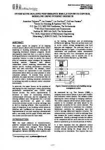
Figure 1: Modeling specialization levels. The triangle stands for generalization, the straight line for instantiation 3.1. Static Models Several levels of refinement are used to reduce the complexity of the model, as shown in Figure 1. Two different relations are used between these levels: specialization (inheritance) and instantiation. The three top levels define a modeling language or ontology. The system level introduces the five subdomains and relations between entities in differ-
914
SCSC 2007
ent domains. The system level also introduces the distinction between immaterial (space) and material (matter) entities. The first specialization is the domain level, giving a specific structure to each sub domain, as for example Figure 2. A further specialization, the application domain level, introduces entities and relations typical for an application domain, for example office buildings, hospitals, or homes. This partitioning reduces the modeling complexity and introduces a terminology for communication with field experts. From the application domain model project level models are derived by instantiations of agent types and relations that are parts of a specific application, as for example the case study. By keeping the number of types small and by another instantiation into agents with individual parameters, the modeling effort can be kept reasonable. This last step is done automatically by compilers and creates the run-time code for execution. Instance parameters can be introduced at run-time. One common feature of all project level models is that no inheritance is used. The reason is that the modeling language SDL-92 [Olsen et al. 1994] which we are using incorporates inheritances, but it is not very obvious what it means in the behavioral models, specifically in state transition graphs. In order to keep the meaning of the models clear to the modeler and also to domain experts, we only use composition as structuring relation. Composition relations create tree structures of agent types which are also projected into the instance structure at runtime. A strict model architecture has been introduced to simplify the construction of agent type structures: all agent types have the same basic structure. They are composed of a process that defines its behavior and of 0..n subagents. Each agent has one input and one output port and all the ports of the subagents are only connected to the parent process. This provides a simple communication structure along the branches of the tree. Such tree structures have the advantage that subtrees can be easily replaced by other subtrees without changing the basic communication structure and thus support model reuse and modifications. A disadvantage is that direct communications between agents without direct composition relations is not possible. This is compensated by a second communication network based on remote procedure calls between agents which can be made visible in the structure diagrams by additional relations. Figure 2 shows the user activity domain model. All entities are types of agent types, marked by a trailing T. On the immaterial left side of the diagram roles of user groups and of individuals are composed of activities. Correspondingly, the roles are realized by groups of individuals and by individuals. This distinction of roles and persons is an important means to be able to let individuals or groups take or quit roles dynamically. For example, a person may have different jobs or a job is done by different persons during a day. An individual has
SCSC 2007
1..*
realizedBy
GroupRoleT 1
roleFct UserGroupT has
*
GroupActT
member 1..* realizedBy
1
IndivRoleT 1
1..*
IndividualT
roleFct 1..*
IndivActT
Figure 2: user activity domain model. The trailing T indicates that all entities are types of agent types personal properties and preferences, whereas a role determines the workflow of a job. In the application domain, roles can be further specialized, for example in university professor, student, or secretary roles. Also, the activities can be refined to lecturing, desk work, moving, meeting. The case study will show how these entities are used.
OrgUnitT
FctUnitT
realizedBy PlaceT InventoryT
Figure 3: Functional unit domain model The functional unit domain model in Figure 3 is of similar simplicity. This is of great importance for our software engineering approach to produce specific simulators for each application with the smallest possible effort. By keeping the number of different types of agents small, the modelling, implementation, and testing effort is also small. 3.2. Dynamic Models The dynamic models are the key to simulation. We use different representations to describe the models during the development process. On the one hand, the models have to be descriptive enough for modelers and domain experts to understand and communicate with each other. For example, the
915
ISBN # 1-56555-316-0
SDL is sufficient to describe models in all details, at the structural level it also uses an abstraction of the composition and communication structure, but it lacks the ability to show the interaction of messages and state transitions in an abstract form. Message Sequence Charts (MSC) are supported by the “Tau SDL Suite” for this purpose, but we found MTCs a better abstraction to develop and document complicated scenarios. We will show an example in Chapter 5.2. Let use start with user groups and individual users. We only model the begin and the end time of the work day and personally induced activities a user performs during the work day. Times off work are of no interest for office building domain simulations. Start and stop times of all activities are modeled as stochastic variables with individual parameters. Typically some parameters can change for every day of the week, others are constant. Since, at the moment, we do not have data about measured probability distributions, we use uniform distributions with average and range as parameters. Typical personal activities during a work day are: get a drink, go to toilet, take a break. All job or role related activities are modeled in the role agent. Other individual specific parameters are preferences related to comfort. They are sent from the individual to the places and are typically temperature and humidity ranges and light levels for different activities. These values may change with the season of the year. Roles of groups and individuals are defined by tasks. Each day the dynamics of roles are determined by schedules of task related activities. We distinguish: continuous activities: typically the work done between other activities, e.g. desk work regular activities: executed at fixed times and durations, e.g.lectures, lunch break irregular activities: executed spontaneously or triggered from the environment, e.g. ad hoc meetings secondary activities: induced by the above activities, e.g. copying, filing These activities are modeled only to the degree of detail that influences the experiment. For example, if we test occupancy detector controlled service systems, it does not matter what is done at the desk or at a meeting. It only matters if a place is occupied or not, at most the number of persons to control air quality. But if task specific automatic lighting is tested, reading, manual drawing, or computer terminal usage should be distinguished, if possible with sensors. Scheduling is based on task priorities. Regular activities can be scheduled for a work day when the role is taken by an individual. Irregular activities are also scheduled at this point randomly in between activities with higher priority, based on a total number per workday or a frequency of events. Continuous activities just fill the time that is left over. Typically, an
modeling expert may be a computer scientist, the domain expert an architect, a work-flow expert, or a control engineer. Therefore, the basic representation is always textual, although in a structured way to be able to manage text components in a structured software development process (see [Zimmermann and Metzger 2004] for more details). MTC
agent1
agent2 state1
state1 msg3
msg1
state2
state1
[condition] msg4
msg2
state2
state2
msg1
agent1
msg2
msg3
agent2
msg4
Figure 4: Simple MTC example with state transitions (top) and abstractions (bottom). Thick arrows denote messages A more formal representation is based on Message Transition Charts (MTC) as shown in Figure 4. In order to explain the need for MTCs we have to explain the behavior of the used model architecture. Multi-agent simulations consist of many independent agents that exchange messages between themselves and with the environment. Agents have internal states and functions, react to and produce messages. Therefore, a perfect model of an agent is a process with states, each executing on an individual digital processor. This would achieve full concurrency of processes and is a good abstraction during modeling. Since this hardware effort is not necessary, many or all processes are mapped onto one processor by a scheduler that simulates the behavior of many processors. Each process is modeled as an extended finite state machine (EFSM) with a message input queue. Messages and timers cause state transitions. A state transition can perform computations, changing the states of local variables, and send new messages. State transitions can depend on conditions. We use the graphical modeling language SDL-92 [Olsen et al. 1994] and a tool environment “Tau SDL Suite” for editing, syntactic and semantic analysis, and debugging [Telelogic]. This environment also provides a code generator that translates the static and dynamic models into executable code and a run-time environment for virtual- or real-time simulations.
ISBN # 1-56555-316-0
916
SCSC 2007
irregular, extending throughout most of the nights and weekends. Existing occupation patterns have been documented in interviews with occupants. Air conditioning is currently provided by forced air from ducts under the raised floor, provided by a central air handling unit. In addition, water mullions, that are vertical water pipes between the window elements, provide radiation above or below air temperature to compensate the window radiation. The mullions also act as radiators. Because of the irregular occupancy, the whole office is heated or cooled 24 hours 7 days per week to guarantee user comfort at all times. This situation will be changed in the future by inserting fan coil units in the floor and by controlling each office separately using occupancy sensors. Central air supply shall be reduced just to provide air quality and to control humidity. Several control strategies shall be compared to find the best compromise between energy savings and comfort. The purpose of the case study is to test control strategies with realistic individual user behavior by simulation before the hardware is installed to be able to select and program control algorithms to be implemented when the hardware becomes operational. Only in such a way the office can be used with minimal disruption. As further experiments it is planned to experiment with different office separation heights, with different occupancy detection schemes, with different combinations of radiation and air temperature to provide comfort, and with natural lighting control. Also, different sets of individual comfort preferences will be tested. Simulation outputs are satisfaction ratings (based on thermal comfort and air quality) and energy consumption. l
individual performs only one continuous activity for the job, for example desk work. This may be the main task of the role, but in practice it gets a low priority and is often interrupted. If a minimum duration for the continuous task is defined by the role, this may lead to extending the work day beyond the time planned by the individual or group. Secondary activities are not scheduled. They are created randomly by an activity, based on role specific frequencies. Personal activities interrupt role activities by messages from the individuals, if the priority is set high enough. If the priority is too low, two things can happen: the interrupt is forgotten, because the activity is no longer necessary (drinks are served at meetings) or handled on the way (go to toilet coming back from a meeting), or the personal activity is postponed until after the current activity. For one important aspect of user behavior we have no solution yet. Users react to changes in the work environment in different ways that are very difficult to predict. Depending on past experience, origin, age, sex or other factors, people will open or close windows and shades, change thermostat or dimmer settings and do all sorts of things that the control strategy would like to avoid. Systems that prevent such interactions produce user dissatisfaction. Also, users adapt to the environment and change their comfort parameters. Therefore, the generally accepted indoor comfort functions do not provide reliable user satisfaction predictions. More analyses in real work environments are necessary before such aspects of user behavior can be modeled for predictions. The NEAT project [Loftness et al. 2006] is a good source of data, but these are not yet developed into an abstract model. 4.
THE CASE STUDY Before project domain models are introduced, the case study is shortly explained. The office example is a part of the Robert L. Preger Intelligent Workplace (IW) that is used by the Center of Building Performance and Diagnostic, Architecture Department, Carnegie Mellon University, Pittsburgh, for staff and student workplaces. It also serves as a lived-in laboratory for HVAC and lighting experiments for teaching and research purposes. The office is in principal open-plan, but due to the regular roof structure, 5m wide parallel bays partition the space. In the south end of the IW, 5 bays are further partitioned into 2 office spaces and a central hall space, providing 10 offices. The partitions are created by furniture of different height, not reaching the ceiling. These separations provide some visual, acoustic, and thermal isolation, but some air can still circulate between adjacent spaces. 3 offices are occupied by one professor each, 1 office is a meeting place, 6 offices have desks for 3 graduate students and visiting scientists each. Due to lectures, meetings, and personal work hour preferences the occupation pattern is very
SCSC 2007
GenSys obj1 IWSouth fdm1
cdm1
sdm1
bdm1
FctUnitDomain
ControlDomain
ServiceDomain
BuildingDomain
udm1 UserActDomain usg1
UserGroup
ind1..25
mpl1
MeetPlace ahc1
cpl1
CircPlace ssc1
Individual
GroupRole spl1..8
grr1 inr1..25
IndivRole ppl1..3
dew1 DeskWork
StudPlace
ahu1
AHUCtrl
fsc1 FCUSupplyCtrl fcp1
rmc ProfPlace 1..10
RoomCtrl
msp1
OccupDet
RoomPanel wmp1
fwa1
Meet
mov1
Move
msc1
MulSupplyCtrl
ssp1
SouthSpace
FCUSupply rom1..10 FCUSupPipe
fcu1..10
occ1 rmp1
AHU
SouthSphCtrl fsp1
Room Facade
fac1..2
FCU
flr1
Floor
MulSupply
rof1
Roof
MulSupPipe
mul1..10
Mullion
env1
Environment
oud1..4
Outdoor
Figure 5: Agent type structure with instance names and cardinalities 5.
PROJECT MODELS For the purpose of the case study, a static agent type model and a dynamic model have been derived from the application domain level as introduced in Chapter 3.
917
ISBN # 1-56555-316-0
Reaction Chain Individual offWork
IndividualRole
Move
DeskWork
undefined
still
idle
atWork
StudentPlace
RoomCtrl
empty
loop
occupyDesk
takeRole (activity, move quitTime) schedule
startTimer
CircPlace
loopTimer
(nP:=1) acting
acting
occupied
wait
empty
setValves setFan loop
[quit] nextActv Timer
breakTimer
(np:=nP+1)
away
occupied atWork
acting
Timer
moving (nP:=nP-1) [nP>0]
actStop
quitTimer
acting/away offWork
undefined
occupied
still
takeBreak
idle
occupied
[occ>0] (setpoint:=day) loop
acting
[quit]
newOcc(1)
release Desk
(nP:=nP-1) [nP=0]
newOcc(0)
empty
[occ>0] (setpoint:=night) loop
empty
Figure 6: MTC of the domains User Activity, Functional Unit Domain, Control Domain for the main workplace scenario and sends a message back to Move to set a timer accordingly. CircPlace also counts the individuals for lighting control. Once at the workplace, e.g. StudentPlace, the continuous activity is executed until IndividualRole triggers another move to another place according to the schedule or the individual takes a break. In the example breaks can only be taken while at the workplace. Breaks at other places are assumed to be either skipped or combined with the other activity. While at the workplace, secondary activities are scheduled randomly according at role induced frequencies. These interruptions are handled in the same way as breaks and are not explicitly shown in the diagram. Workplace occupancy changes environment requirements, such as air temperature, light setpoints, and fresh air volume in the RoomCtrl. This results in changes of valve and fan speed settings of the fan coil units and other parameters. The scenario shows how many agents are involved in the control system of an office, if user activities are considered. MTCs are a good means to create a dynamic model that can be refined and translated into an SDL model. Group meetings are different scenarios, not shown here. Additional MTCs have been created for the interaction of the control agents with service and building domain agents. It has to be pointed out that MTCs are only an intermediate step in the modeling process and do not have to be complete. Completeness is required from SDL models only. As already introduced in Chapter 3, user activity models are so far based on stochastic variables that govern entry and exit times of all activities. The parameters of the distribution functions are different for each experiment setup. In experi-
5.1. Static Model Figure 5 shows the agent structure of the complete simulator for the case study. The components can be easily recognized by descriptive names. Each domain is represented by a common node, for example on the left the UserActivityDomain. These nodes have data distribution and collection functions. The node IWSouth represents simulation control functions such as time synchronization and file handling. The root node is the instance management node GenSys that at system start propagates unique instance names to all agents and retrieves unique process ids for remote procedure calls. Unique names of nodes are constructed by concatenating all instance names of the tree branch above the node. GenSys also provides typical functional extensions to SDL that are used in simulations and control systems. The two top nodes are part of a universal simulation environment, the five domain nodes are reused in all building system simulations, all other nodes are project specific, but can be modified and reused in different projects. In our process, reuse means reuse of models, since code is automatically generated. 5.2. Dynamic models In Figure 6 the main state transitions and messages are shown in an MTC. At first sight this looks rather confusing and we will try to follow the main path of events for a typical scenario from left to right. Depending on individual preferences and role requirements, startTimer triggers the begin of a work day. Each individual takes up a role which starts with scheduling the regular and irregular tasks for the work day. Typically, the individual moves from the entrance to its workplace, using CircPlace. CircPlace knows the distances
ISBN # 1-56555-316-0
918
SCSC 2007
cessor. One simulation run takes 24 minutes accordingly, with set-up times about 30 minutes. For the shown simulations all 10 office spaces were assumed to be separated by walls with indefinite heat resistance to give the largest possible differences between occupancy patterns. Also, the AHU and the mullions have been turned off. All controllers have been assumed to be simple P-controllers. These simplifications have been used to concentrate on the dynamics and the influence of individual user activities. The simulations of all physical components are based on first principles. Room dynamics consider the heat capacitances of walls and furniture. Hot and cold water dynamics are modeled by time delays. Heating and cooling energy calculations are based on supply water temperature differences and flows, integrated over time. The sampling time periods of all different agents are adjusted to the individual time constants.
ment 4 the data from interviews with occupants in the IW are used, the other experiments use constructed parameters. Scheduling is performed in a very simple way, based on the personal experience of the author. Coming into work in the morning, only the regular tasks are scheduled, everything else develops during the day. Attempts for optimal schedules are not the reality. Priority for the main continuous activity is normally low, only increased in the case of strict deadlines. Any more sophisticated scheduling strategies would not provide better experimental results in the case study. 6.
THE SOFTWARE ENGINEERING APPROACH As already mentioned, the formal SDL-92 models are executable. This means that they contain all information necessary to execute a simulation. Because SDL semantics are well defined, models can be translated by compilers into executable code. SDL uses two types of graphical representations: one describes the static component hierarchy of each agent type and its instances, thus representing structures as in Figure 5. The other describes the dynamic model of each agent as processes and communication interfaces, as explained in Chapter 3.2. In this way SDL is used as a very high level graphical programming language that is translated automatically into a high level language, in this case into C. This is the basis of our software engineering approach. On the basis of this, a software engineering process PROBAnD [Metzger and Queins 2002] has been defined with additional structured text documents to guide the designer from informal descriptions to formal models. The process is also based on the model architecture shortly described in Chapter 3. Together with a simple version management and a development time recording tool the process is made as efficient as possible. This allows the fast creation of models and simulators for every simulation project from scratch if necessary. This process is further supported by a tool PROTAGONIST that translates structured textual descriptions into SDL models [Metzger and Queins 2003]. In projects with known simulation principles a development time of about 2 personhours per agent type could be achieved. In the current project with 38 new agent types and some new principles, the time had to be doubled. This effort is still in the time range necessary to personalize commercial simulation environments, if they existed for all five domains.
Table 1: Experimental results Exp
Heating Energy
Cooling Energy
Total Energy
1
24h/day
16.1kWh
1.8kWh
17.9kWh
2
0h/day
11.9kWh
0.8kWh
12.7kWh
3
8-17/day
13.9kWh
1.0kWh
14.9kWh
4
actual usage
13.8kWh
1.1kWh
14.9kWh
Table 1 shows some simulation results. Since heating and cooling is provided by the university in the form of hot and chilled grid water supplies and mixed to appropriate temperatures in local supply circuits, energy calculations are based on water flow and the supply and return temperature differences. Exp 1 shows the worst case, 24h heating and cooling with daytime setpoints because of the irregular work hours of the occupants. In contrast, the best case in Exp 2 assumes no occupation at any time and thus 24h nighttime setpoints. Exp 3 shows the energy consumption of an office with regular work hours, in the middle between best and worst case. Under the assumption that the occupants in a university office are less than 9 hours at their desk because of classes and meetings, but at irregular times of the day, a good occupancy controlled air conditioning system should reach the same values as in Exp 3. Exp 4 happens to show this result. Any other occupancy pattern will give different results. Also, the energy consumption will grow with increased heat permeability of the inter office walls.
7.
EXPERIMENTAL RESULTS All experiments were conducted with weather files from a station in the University of Kaiserslautern [Litz]. All data are recorded every minute, providing a sufficient resolution even for light and radiation on cloudy days. From 2003, days 1 to 5 of each month have been combined to 60 consecutive days. The simulation is set up to compute each hour in one second real-time on a laptop with an 850MHz Pentium pro-
SCSC 2007
Description
919
ISBN # 1-56555-316-0
Litz. http://wetter.eit.uni-kl.de/ Loftness, V. et al., 2006, “Workplace 20•20 Field Evaluation of Baseline Environmental Quality & NEAT National Environmental Assessment Toolkit”, ABSIC Meeting. Mahdavi A. 2007, “People as Power Plants - Energy Implications of User Behavior in Office Buildings.” Proc. Intern. Energiewirtschaftstagung (IEWT), Vienna. Meyer-König T. et al. 2005, “Implementing Ship Motion in ARENAS - Model Development and First Results.” In Proc. Pedestrian and Evacuation Dynamics, Vienna, 429441. Metzger, A. and Queins, S. 2002. “Specifying Building Automation Systems with PROBAnD, a Method Based on Prototyping, Reuse, and Object-orientation.” GI-Edition, Lecture Notes in Informatics (LNI), P-5. Bonn: Köllen Verlag, 135–140. Metzger, A and Queins, S. 2003, “Model-Based Generation of SDL Specifications for the Early Prototyping of Reactive Systems.” Telecommunications and beyond: The Broader Applicability of SDL and MSC. Springer Lecture Notes in Computer Science, LNCS 2599. Heidelberg: Springer-Verlag, 158–169. Olsen, A. et al. 1994. System Engineering using SDL-92. Amsterdam: Elsevier. Tabak, V. et al. 2005. “Model for Office Building Usage Simulation.” In Proc. Pedestrian and Evacuation Dynamics, Vienna 2005, 391-403. Telelogic Tau SDL Suite, http://www.telelogic.com Vityaz, O. and Zimmermann, G. 2005, “Real-Time Simulation Using Graceful Degradation of Accuracy”, Energy and Buildings, Volume 37, Issue 8, August, 795-806. Zimmermann, G. 2001. “A new approach to building simulation based on communicating objects.” Seventh International IBPSA Conference Proceedings. Vol. 2. Rio de Janeiro, Brazil, 707–714. Zimmermann, G. 2002. “Efficient creation of building performance simulators using automatic code generation.” Energy and Buildings. 34. (2002): 973–983. Zimmermann, G. 2003. “Modeling the building as a system.” Eighth International IBPSA Conference Proceedings. Eindhoven, Netherlands. (2003): 1483–1490. Zimmermann, G and Metzger, A. 2004. “A software-generation process for user-centered dynamic building system models.” Proc. ECPPM 2004, Istanbul. Zimmermann, G. 2006a, “Multi-Agent Model to Multi-Process Transformation - A housing market case study.” In Proc. 8th International Design and Decision Support Systems Conference, Einhoven, 203-219. Zimmermann, G. 2006b, “Modeling and Simulation of Dynamic User Behavior in Buildings - a Lighting Control Case Study.” In Proceedings ECPPM'2006, Valencia.
8.
CONCLUSION AND OUTLOOK Our main result is that user activities of individuals and groups in office environments can be modeled on the basis communicating agents. By separating persons from roles and work places, the individual agents are relative simple entities. They are personalized by parameters such that a small number of agent types has to be modeled and implemented. Integration into building performance simulations is achieved by modeling the building fabric, service system components and control subsystems as agents as well in the same modeling and implementation environment. Experiments show that this approach is feasible, provides tangible results, and executes in acceptable run times despite automatically generated simulation codes. As further extensions, the building and service models will be refined and different control strategies will be developed and tested, including user satisfaction models. Also, the simulated user activity patterns will be compared with observations of real patterns and changed accordingly. It is planned to use the observations in other environments to extend, refine, and generalize the user activity model. Also, its application in building space utilization simulations will be tested. Another, more important goal is the modeling and simulation of user reactions to new building control and service strategies. Humans are very adaptable and often counteract to the intentions of energy saving systems, thus letting the intentions fail. Simulation could help to predict and avoid such failures. This research is based on results from earlier projects funded by the Deutsche Forschungsgemeinschaft and is partially supported by the Center for Building Performance, CMU. The author also has to thank for the use of the experimental facilities and informations of the Robert L. Preger Intelligent Workplace. References Devisch, O.T.J et al. 2006, “Modeling Residential Search and Location Choice.” In Proc. 8th International Design and Decision Support Systems Conference, Einhoven, 185-200. Dijkstra, J. and Timmermans, H. 2002, “Towards a multiagent model for visualizing simulated user behavior to support the assessment of design performance.” Automation in Construction, 11, 135–145. Eastman, C. M. and Siabiris, A. 1995, “A generic building model incorporating building type information.” Automation in Construction. 3: 283–304. Eckholm, A.and Fridquist, S. 2000, “A concept of space for building classification, product modelling, and design.” Automation in Construction 9, 315–328. Hewitt, D. et al. 2005, “A Market-Friendly Post-Occupancy Evaluation: Building Performance Report.” Final ReportContract C 10091, New Buildings Institute. ifc2x3: http://www.iai-international.org/Model/R2x3_final
ISBN # 1-56555-316-0
920
SCSC 2007