Modeling and Understanding End-to-End Class of Service Policies in Operational Networks Yu-Wei Eric Sung† , Carsten Lund‡ , Mark Lyn? , Sanjay Rao† , and Subhabrata Sen‡ †
Purdue University, ‡ AT&T Labs – Research, ? AT&T Inc.
{sungy,sanjay}@ecn.purdue.edu, {lund,sen}@research.att.com,
[email protected] ABSTRACT Business and economic considerations are driving the extensive use of service differentiation in Virtual Private Networks (VPNs) operated for business enterprises today. The resulting Class of Service (CoS) designs embed complex policy decisions based on the described priorities of various applications, extent of bandwidth availability, and cost considerations. These inherently complex high-level policies are realized through low-level router configurations. The configuration process is tedious and error-prone given the highly intertwined nature of CoS configuration, the multiple router configurations over which the policies are instantiated, and the complex access control lists (ACLs) involved. Our contributions include (i) a formal approach to modeling CoS policies from router configuration files in a precise manner; (ii) a practical and computationally efficient tool that can determine the CoS treatments received by an arbitrary set of flows across multiple routers; and (iii) a validation of our approach in enabling applications such as troubleshooting, auditing, and visualization of network-wide CoS design, using router configuration data from a cross-section of 150 diverse enterprise VPNs. To our knowledge, this is the first effort aimed at modeling and analyzing CoS configurations. Categories and Subject Descriptors: C.2.3 [Network Operations]: Network Management General Terms: Design, Management, Measurement Keywords: Configuration modeling, differentiated service
1. INTRODUCTION Service differentiation using Class of Service (CoS) is being increasingly adopted in a wide variety of network settings including enterprise Virtual Private Networks (VPNs). The need to support CoS differentiation arises from several considerations: (i) IP networks today carry traffic from a diverse set of applications with very different performance needs such as low delay and low loss for Voice over IP (VoIP) traffic, and high throughput for bulk data transfer like FTP; (ii) different applications can have very different relative importance to an enterprise customer, e.g., web service transactions supporting a vital workflow are likely to be accorded
Permission to make digital or hard copies of all or part of this work for personal or classroom use is granted without fee provided that copies are not made or distributed for profit or commercial advantage and that copies bear this notice and the full citation on the first page. To copy otherwise, to republish, to post on servers or to redistribute to lists, requires prior specific permission and/or a fee. SIGCOMM’09, August 17–21, 2009, Barcelona, Spain. Copyright 2009 ACM 978-1-60558-594-9/09/08 ...$10.00.
much higher priority compared to traffic associated with browsing external web sites; and (iii) economic considerations drive the need to optimize the usage of existing network infrastructures under finite capacity and cost constraints, while ensuring good performance for important applications. CoS designs embed inherently complex policy decisions based on the described priorities of various applications, extent of bandwidth availability, and cost considerations. Realizing these policy objectives involves configuring multiple routers in low-level, device-specific configuration languages. Troubleshooting customer complaints regarding poor performance involves tracing the configured CoS treatment of individual flows by looking across router configuration files, each of which can contain thousands of command lines. Misconfiguration could potentially lead to violations of the service level agreements (SLAs), business service disruptions for the enterprise, and penalties for the service provider. The problem is daunting considering the large number of enterprise networks managed, their large size and geographical span, and the diversity of services and configuration options. While managing network configuration is hard in general, CoS configuration poses several unique challenges. First, CoS configuration is highly intertwined, with dependencies across different parts of a configuration file. Second, the overall CoS treatment seen by a flow between two end-points may be impacted by policy blocks (i.e., parts of the configuration specifying CoS policy rules) instantiated in multiple device, possibly on both input and output interfaces of each device, and by multiple policy blocks even on a single interface. Third, each policy block can transform a packet before it enters the next policy block – for instance, a router may mark a packet at the inbound interface to indicate the priority class, and the actions of the router’s outbound interface or a downstream router may depend on the marking. Finally, each policy block classifies flows into different classes using multiple access control lists (ACLs), each of which can have hundreds of inter-dependent rules.
1.1 Contributions In this paper, we make the following contributions: • We draw attention to the prevalence of CoS, and the complexity inherent in managing CoS configuration, a topic that is little known outside the operational community. Our understanding has been gleaned from repeated inspections of router configuration files from a large number of enterprise VPNs, and through close interactions with network designers. We believe our efforts pave the way for the research community to further engage in the area. • We propose a formal representation of CoS policies that is independent of the underlying configuration syntax. This representation is easily derivable from low-level configurations and can enable us to systematically compose CoS policies across multiple policy blocks within a single router and across multiple routers.
Enterprise VPN New York
LA Æ Dallas branch traffic
LA
San Diego
CER1
PER4
CER: Customer-Edge Router PER: Provider-Edge Router
LA
Dallas
PER3
P routers CER1
MPLS Backbone
CER4b
CER4
CER3 PER1
Dallas PER2
CER2 CER5
Houston
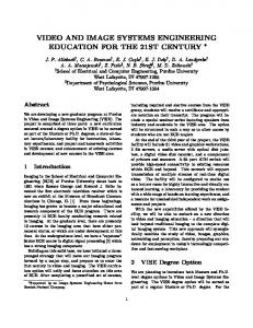
Figure 1: An enterprise VPN spanning multiple sites. • Based on our framework, we have built a query tool that enables operators to determine how an arbitrary set of flows are treated on an “end-to-end” basis. We use the term “end-to-end” throughout this paper to refer to the fact that the tool can model the net effect that a flow would see if it were to traverse a given sequence of devices, each of which could potentially have multiple CoS policy blocks. The set of devices of interest is assumed to be known, though in the future, routing table information could be incorporated to automate the discovery of the devices involved. The tool leverages binary decision diagrams (BDD) [14], a practical and efficient data structure for manipulating boolean operations. With our tool, the computation time for query resolution is in the order of seconds for the real-world datasets we considered. While we believe our modeling approach is itself more general, the current implementation of the tool is targeted at Cisco IOS configurations, and enterprise VPN settings. Further, the focus is on CoS policies instantiated in routers at the customer and provider edge, at both the ingress and egress. We focus on these policies as they reflect unique requirements of individual customers and tend to change frequently. CoS policies in the core are not considered as they reflect provider policies which are relatively homogeneous and stable, and do not involve IP packet transformations. • We have evaluated our tool on a cross-section of 150 different enterprise VPNs. Even though the VPNs are managed by the same provider, their CoS designs show significant diversity across enterprises, perhaps reflecting the different application mixes and cost considerations of each enterprise. Further, their designs show a large degree of heterogeneity in terms of how different routers within an enterprise are configured, reflecting the different functionality offered by sites within an enterprise (e.g., a VoIP customer service center may be configured differently than a data center). The results also confirm the importance and effectiveness of our approach in assisting operators to reason about network-wide CoS operations. In particular, our tool enables operators to audit the overall CoS design, identify potentially anomalous flow treatments and configuration lines that are never triggered, and derive a network-wide view of the CoS design which summarizes the traffic classes that can be exchanged between every pair of VPN sites. The rest of the paper is organized as follows. §2 presents the background on CoS in enterprise VPN settings and motivates our formal modeling approach. §3 describes a framework for modeling CoS configuration. §4 outlines the design and key implementation aspects of our CoS query tool. §5 describes potential usage scenarios for the tool. §6 studies CoS usage in practice and evaluates the effectiveness of the tool in troubleshooting, auditing, and deriving network-wide CoS designs. §7 summarizes related works. §8 discusses some open issues, and finally §9 concludes the paper.
2. BACKGROUND AND MOTIVATION Enterprise networks are increasingly moving from using dedicated private lines to using VPNs, especially layer-3 Multi Protocol
PER1
PER2
CER2
Packets are Packets are still marked marked Packets are policed with the same DSCP inbound off depending on whether LAN – given they are conforming or MPLS VPN Backbone value as they were when they left CER1. DSCP setting non-conforming. for appropriate DSCP-based CoS Packets are scheduled Packets are scheduled CoS. using various queuing EXP-based CoS using various queuing disciplines and disciplines and congestion avoidance congestion avoidance mechanisms. mechanisms.
Figure 2: CoS treatment along an end-to-end path. Label Switching (MPLS) VPN technology, to connect geographically disparate sites. In this architecture (see Fig. 1), each site has one or more customer edge routers (CER), which can be jointly configured by the enterprise customer and service provider. Each CER connects to the provider network via one or more provider edge routers (PER). Customer IP traffic from a CER is encapsulated by MPLS labels at the ingress PER, carried over MPLS tunnels across core routers (referred to as Provider or P routers) in the MPLS provider backbone, decapsulated by a remote egress PER, and sent to the appropriate destination CER. Such provider-based VPNs provide a scalable and secure way for service providers to support different customers across a common MPLS backbone.
2.1 Service differentiation in VPNs A primary consideration for service providers in designing enterprise VPNs is to satisfy various application needs such as delay, jitter, and bandwidth. In this architecture, both the enterprise and provider are faced with supporting traffic for applications with different performance requirements and service priorities over a common network infrastructure. Furthermore, in the provider backbone, services with different requirements such as VPNs, Internet, multicast, and VoIP may coexist. At the edge of the network, between the enterprise and the provider, limited available bandwidth capacity coupled with the high cost of deploying and provisioning additional capacity means that bandwidth needs to be carefully managed across the applications competing for it. While the core is typically overprovisioned, bandwidth must still be carefully managed under failure scenarios. Service differentiation is essential to traffic management in such a heterogeneous environment. A provider and an enterprise customer enter into service level agreements (SLAs) that describe the agreed-to requirements on performance for different applications – this involves complex choices based on application requirements and behaviors, the relative priorities of applications used by that enterprise, and cost. The routers in the VPN need to then be configured appropriately to honor the SLAs. SLA violations can have adverse consequences, potentially involving disruption of critical enterprise activity and heavy penalties for the service provider.
2.2 Realizing service differentiation using CoS Class of Service (CoS) is a way of realizing service differentiation, by grouping traffic with similar service requirements and treating each group as a class with its own level of service priority. The Type of Service (ToS) field of the IP header of each packet indicates the priority class to which it belongs. Typically, the first 6 bits of the ToS field encodes the class information, and these bits are referred to as the Differentiated Services Code Point (DSCP) bits. The DSCP bits are directly used by the CERs and PERs in deciding the treatment that a packet must receive on the CER-PER
1 2 3 4 5 6 7 8 9 10 11 12 13 14 15 16 17 18 19 20 21 22 23 24 25 26 27 28 29 30 31 32 33 34 35 36 37 38
class-map match-any REALTIME match access-group VOICE match access-group INTERACTIVE-VIDEO match ip dscp 46 class-map match-all ... ! OTHER class-maps ! policy-map REALTIME-POLICER class REALTIME police 30000 conform-action set-dscp-transmit 46 exceed-action drop policy-map CRITICAL-DATA-POLICER class ROUTING set ip dscp 48 class OTHER-CRITICAL-DATA police 15000 conform-action set-dscp-transmit 26 exceed-action set-dscp-transmit 28 policy-map BEST-EFFORT-MARKER ... ! policy-map WAN-EGRESS-POLICER-QUEUE class REALTIME priority percent 35 service-policy REALTIME-POLICER class CRITICAL-DATA bandwidth percent 40 service-policy CRITICAL-DATA-POLICER class class-default bandwidth percent 25 service-policy BEST-EFFORT-MARKER ! interface Ethernet0/1 ! INTERFACE TO LA BRANCH’s LAN ... ! LAN INGRESS MARKING POLICY ! interface Serial1/0 ! INTERFACE TO PER1 service-policy output WAN-EGRESS-POLICER-QUEUE ! ip access-list extended VOICE permit ip 192.168.1.0 0.0.0.255 any permit ip any 192.168.1.0 0.0.0.255 ip access-list ... ! ACLs FOR OTHER TRAFFIC TYPES
Figure 3: Class of Service configuration of CER1. and PER-CER links. Before forwarding an IP packet to the backbone, the PER encapsulates it with an MPLS label and maps the DSCP value of the packet to a 3-bit field in the MPLS label referred to as the experimental (EXP) value. This EXP value is used by P routers to differentially treat traffic in the core. Fig. 2 illustrates the overall process of realizing differentiated treatment along an end-to-end path. Based on the SLAs and customer input, the network designer is tasked with determining the CoS policies to instantiate at each CER and PER for a given VPN. Conceptually, there are three main components to CoS policies: • Marking: This component involves rules to determine how incoming traffic may be assigned to a particular class by setting appropriate ToS values based on packet parameters. Typically, the parameters used are a subset of the 6-tuple: source and destination IPs and ports, protocol, and ToS. Note that the ToS field is included as the classification decision may depend on the ToS field set by an earlier device, e.g., a router at the customer premise. • Policing: This component involves rules that determine whether the packet arrival rate of a class conforms to the specified traffic rates and what actions should be taken. For example, conformant and non-conformant traffic of each data class could be assigned different DSCP bits to indicate they must be treated differently. Alternately, non-conformant traffic could simply be dropped. • Queuing: This component applies queuing rules to outgoing router interfaces that may experience congestion (e.g., a PER-facing CER interface). The rules for each queue specify the discipline (e.g., RED, Weighted Fair Queuing) and allocated bandwidth of the queue, as well as attributes (e.g., drop rate) for different traffic classes assigned to the queue.
1 2 3 4 5 6 7 8 9 10 11 12 13 14 15 16 17 18 19
class-map match-any REALTIME match ip dscp 46 class-map match-any CRITICAL-DATA match ip dscp 48 match ip dscp 26 match ip dscp 28 ! policy-map WAN-INGRESS-POLICING class REALTIME police 95000 conform-action set-mpls-exp-transmit 5 exceed-action drop class CRITICAL-DATA police 60000 conform-action set-mpls-exp-transmit 3 exceed-action set-mpls-exp-transmit 7 class class-default police 75000 conform-action set-mpls-exp-transmit 0 exceed-action set-mpls-exp-transmit 4 ! interface Serial1/0 ! INTERFACE TO CER1 service-policy input WAN-INGRESS-POLICING service-policy output WAN-EGRESS-QUEUE ! TO LA !
Figure 4: Class of Service configuration of PER1.
2.3 Complexity of CoS configuration In this section, we draw attention to a few key aspects of CoS configuration that make CoS policies particularly complex to manage and understand. Our insights are drawn from extensive analysis of configuration data from operational enterprise VPNs (see §6). Our discussion is conducted in the context of Fig. 3 and Fig. 4 which respectively present CoS configuration snippets of CER1 and PER1 in Fig. 2. The configurations are based on Cisco IOS and are significantly simplified for ease of illustration. Instantiated over multiple devices: CoS policies may be instantiated at the CERs, PERs, and P routers, all of which may impact the treatment of a flow traversing these routers. For example, policies in the ingress CER are customized to individual customers and impact how different traffic flows are prioritized on the CER-PER link. Policies in the ingress PER typically set the appropriate EXP value in the MPLS label based on the DSCP marking from the ingress CER, and traffic conformance. Policies in the P routers determine the per-hop queuing strategy inside the core based on the EXP bits and are typically homogeneous across enterprises since they reflect provider-level priorities inside the backbone. Finally, policies in the egress PER prioritize flows on the PER-CER link according to their ToS values. Diversity and dynamics of customer policies: The configuration of the ingress CER is tailored to meet the unique requirements of individual customers. As our analysis of real enterprise VPN datasets in §6.2 will show, CERs within an enterprise VPN may be very different and heterogeneous in terms of the data classes that each CER supports, while the polices used across enterprises may be very diverse. Further, these policies are very dynamic, requiring configuration changes over time to reflect the evolving nature of customer requirements, emergence of new applications, and shifts in traffic patterns (e.g., migration of a database server to another site). Multiple policy blocks per device: The CoS configuration of each router can be composed of multiple CoS policy blocks. Typically, the output PER-facing interface of a CER is associated with two policy blocks, corresponding to the policing and queuing rules. In addition, every input interface may be associated with a policy block corresponding to the marking rules, or the marking rules may be merged with the policing rules on the output interface. Fig. 3 illustrates CER1’s configuration, which employs the latter style. Lines 32-34 show the definition of the PER1-facing WAN interface, which is associated with a single policy construct embedding two egress policy blocks (policing and queueing). Lines 18-28 show
100
CER
CONFIG BLOCK
CDF(CER)
80
60
Ethernet0/1
……
LAN-POLICY
……
policy-map (parent)
WAN-EGRESS-POLICER-QUEUE CRITICAL-DATA-POLICER
40
……
……
REALTIME-POLICER
policy-map (child)
BEST-EFFORT-MARKER
20
ROUTING REALTIME
0
interface
Serial1/0
0
100 200 300 400 Number of ACL rules related to CoS
classdefault
CRITICALDATA
OTHER-CRITICALDATA
500
Figure 5: CDF of the number of CoS-related ACL rules per CER.
……
INTERACTIVEVIDEO
VOICE
TRANSACTIONALDATA
BGP
class-map
access-list
Figure 6: Syntactic reference structure of configuration in Fig. 3. the definition of the queuing policy block, and lines 7-17 show the definition of the policing block. Each of these configuration blocks starts with the keyword policy-map and is organized into multiple sub-blocks, each of which starts with the keyword class. Each of these sub-blocks corresponds to a particular class of traffic, and defines the (policing or queuing) rules for that class. For instance, for the REALTIME class, line 9 indicates that based on the parameter, traffic is either marked with a DSCP value of 46 to indicate it is conformant, or dropped if it is non-conformant, while line 20 indicates that the queueing discipline to be used is a priority queue. Specifying class membership using multiple large ACLs: Flows are usually classified into different classes by using multiple ACLs. For instance, in Fig. 3, the class membership is specified in lines 1-5 using configuration blocks that start with the keyword class-map. Each class-map identifies matching flows with a list of criteria, such as ACLs (lines 2-3) or packet parameters (line 4), and based on the match-all or match-any keyword might declare a packet to be a member of that class if all or any of the criteria is matched. An ACL consists of a list of permit/deny rules evaluated sequentially, and the membership described by an ACL includes all the permitted flows. For example, the ACL used by line 2 describes VOICE traffic with two permit rules (lines 35-37). Fig. 5 shows a CDF of the total number of ACL rules used by CoS policies configured in a CER, across all VPNs in our dataset. We see that more than 100 ACL rules are configured for CoS in 20% of the CERs, and the CER with the most ACL rules has more than 500 rules. Discussions with the designers revealed that the large number of rules may be due to (i) a customer not using contiguous subnet or port ranges to classify applications; and (ii) evolution of classification policies, when ACL entries are added without consolidating existing entries. Given that each policy block can specify membership of multiple classes, each expressed as a logical combination of multiple ACLs with potentially hundreds of rules, manually determining the class which each flow in a set of flows belongs to is impractical from the perspective of operators. Transformations of flows: Each CoS policy block may modify the packet headers or MPLS labels, impacting how they are treated at the next policy block or device. For instance, marking rules may be instantiated in the input LAN-facing interface of a CER, which can modify the DSCP header of a packet, which in turn affects how the packet is treated by the policing and queueing rules. Likewise, the treatment of a flow at the PER may depend on how it has been marked at the CER. Fig. 4 presents a configuration snippet of PER1. The configuration has a similar structure to that of CER1. For each class of traffic, the appropriate EXP value in the MPLS label is set based on the DSCP value and traffic conformance as shown in the policy-map block in lines 8-15. Interestingly, we note that traffic is labeled with the same EXP bits for multiple DSCP values of 48, 26, and 28. Thus, though the traffic belonging to these classes may
be treated differently at the CER1-PER1 link, they are treated in the same fashion in the backbone. Given such complexity in design, it is necessary to consider potential transformations by every router in determining the end-to-end treatment of a flow. Potential for errors: CoS configuration is highly intertwined, with several dependencies that exist across different logical blocks of the configuration. Fig. 6 illustrates the syntactic dependencies of CER1’s configuration. Configurations with such a highly intertwined structure are hard to manually navigate and prone to misconfigurations. An example misconfiguration may involve realtime traffic being incorrectly configured to enter the queue corresponding to best-effort traffic. As another example, errors may arise due to the complex ordering relationships in the configuration. For instance, consider the policy-map block in lines 18-28 of Fig. 3. If the class-map REALTIME had a catch-all clause (all traffic is matched), then, no traffic would match the class CRITICALDATA. This would imply that no traffic would be sent to that particular queue, even though this is not obvious from a casual inspection of the configuration. We refer to a situation where a policy corresponding to a traffic class can never see traffic as a shadowed policy. We discuss more examples of such errors in §6.
3. MODELING CLASS OF SERVICE In this section, we present a model to extract the end-to-end CoS policies between a pair of devices from low-level configurations. We view such a model as an essential building block that can enable applications useful to operators such as troubleshooting, visualization of network-wide CoS designs, auditing, and analysis of configuration changes. Performing these tasks is challenging today due to the complex nature of CoS configuration, motivating the need for formal modeling of CoS policies. In modeling CoS configuration, we had several objectives. First, we wanted a formal representation of CoS policies that precisely and unambiguously captures the policy goals, yet is independent of low-level configuration syntax. Second, the representation should be easily derivable from low-level configurations through a simple parser. Third, we wanted the representation to be amenable to composition, i.e., it should be possible to compose the formal representations corresponding to different policy blocks in a router, or across routers to obtain an end-to-end view of the CoS design. We provide an overview of our approach to achieve these goals in §3.1, and discuss the details in the rest of the section.
3.1 Overview We model the overall CoS policy as a function that we call a ruleset that takes a multiple dimensional input and produces an output. The input is a flowset, which is an arbitrary set of flows. A single flow is identified by the 6-tuple IP header fields: source and
destination IP addresses, source and destination port numbers, protocol, and ToS byte. In addition, there may be other inputs that model attributes outside the scope of a static analysis. For example, a policing policy treats packets differently depending on their conformance to the SLA. We handle this by having an additional bit in the input that specifies whether the model should treat the packets in a flow as conformant or not. The output provides information about the treatment seen by a packet corresponding to each flow (e.g., which queue would be used by the packet), how the packet gets changed (e.g., how the routers modify the ToS byte), and where the packet ends up (e.g., does it get dropped by a policer if non-conformant). Our overall approach consists of three steps: • First, we construct a root ruleset that models each CoS policy block of every device from the configuration files. For instance, for the CER configuration in Fig. 3, two root rulesets are constructed, which correspond to the policing rules (lines 7-17) and the queuing rules (lines 18-28). For the PER configuration in Fig. 4, one root ruleset is constructed corresponding to the policing rules (lines 815). • We initially begin with a representation of a root ruleset which is itself expressed in terms of other rulesets. These dependencies mirror the inherent nested structure of configuration, enabling the root ruleset to be easily derivable from the low-level configurations. We then show how a flat representation which eliminates these dependencies may be derived. The flat representation makes it feasible to compose multiple root rulesets. • Finally, we model the end-to-end CoS policy as a sequence of root rulesets in flat representation, with each root ruleset being allowed to transform the input before sending it to the next root ruleset. We take such a sequence and collapse it into one single ruleset in flat representation that contains the overall CoS behavior.
3.2 Recursive representation of rulesets A ruleset can be viewed as a generalization of access control lists (ACLs), typically used for reachability control [18]. A standard ACL has only two basic actions: “permit” and “deny”. Thus, it can be seen as a function that maps an input to one of these two output values. A ruleset generalizes the notion in a few ways. First, a ruleset may recursively depend on other rulesets. The ruleset at the top of the recursive hierarchy is a root ruleset that encompasses a single CoS policy block. The rulesets at the bottom of the hierarchy, which we refer to as leaf rulesets, capture the matching criteria for a flow (typically by using ACLs). Second, a ruleset permits a broader range of actions than simple permit/deny. Third, a ruleset can have an output action that transforms an input and forwards it to another ruleset. We note however that only the root ruleset is allowed to have an output action that transforms the input – the other rulesets in the hierarchy are restricted to having simple outputs. More formally, a ruleset is represented as a table F that maps an input N-tuple flow f to an output action. Each column j in the table is associated with either a basic field value (e.g., source IP) of the input flow f (denoted by vj (f )), or another ruleset Fj , which is itself represented as another mapping table. Let varsF = {j| column j is associated with a basic input field}. For j ∈ varsF , the cell Fij specifies a match expression. The match expression can include wildcards, and ranges of values just like for standard ACLs. For j ∈ 6 varsF the cell Fij contains a subset of possible outputs that could be produced by ruleset Fj . In addition, for each row i, an output action act(i) gives the output of this row. Given an input flow f we evaluate a ruleset by recursively evaluating the Fj for each j ∈ 6 varsF . Flow f is said to match a row i if and only if it matches every cell in row i. The output of table F given an
VOICE
srcIP srcPort destIP destPort protocol output 192.168.1.0/24 * * * permit * * * 192.168.1.0/24 * permit * * * * * deny *
(a) VOICE
REALTIME
CRITICALDATA
ROUTING
ok * * * *
* ok ok ok *
* ok * * *
INTERACTIVEdscp output VIDEO * permit * *
permit * * *
* * 46 *
ok ok ok no
(b) REALTIME OTHERCRITICAL- output DATA * * ok * *
P1 P2 P3 P4 P5
(c) WAN-EGRESS-POLICER-QUEUE (Policer)
REALTIME ok * *
CRITICALoutput DATA * Q1 ok Q2 * Q3
(d) WAN-EGRESS-POLICER-QUEUE (Queue)
Figure 7: Recursive ruleset representation of CoS configuration in Fig. 3. Columns in italics refer to rulesets which are not shown.
input flow f , denoted F (f ), is defined as the output action for the row with the smallest index i that matches f , i.e., the action for the first-matching row is taken. If no match is found until the end of the table, a special output empty is associated with the flow. Example: Fig. 7 shows how the example configuration presented in Fig. 3 can be depicted using two recursive hierarchies of rulesets. Fig. 3 has two CoS policy blocks describing the policing rules (lines 7-17) and queueing rules (lines 18-28). Each of these blocks corresponds to a root ruleset as shown in Fig. 7(c) and Fig. 7(d), respectively. Each ACL can be represented as a leaf ruleset, while configuration constructs such as class-map correspond to intermediate rulesets. For instance, Fig. 7(a) and 7(b) respectively show the ruleset representation of the ACL VOICE and the class-map REALTIME. Intermediate and root rulesets are expressed in terms of other rulesets lower in the hierarchy. For instance, consider Fig. 7(b). The first two columns refer to the outputs of the rulesets VOICE and INTERACTIVE-VIDEO. The first row is matched as long as the ruleset VOICE produces an output of permit. The second row is matched for flows not matching the ruleset VOICE, but matching the ruleset INTERACTIVE-VIDEO. The remaining rows are matched in a similar fashion. Likewise, in Fig. 7(c), each column refers to the output of the ruleset indicated, and the output action of each row corresponds to a policing rule to be invoked. For example, the policing rule P2 (line 12 in Fig. 3) is invoked only if both the CRITICAL-DATA and ROUTING rulesets are matched, and the REALTIME ruleset is not matched.
3.3 Flat representation of rulesets The representation of a ruleset as defined in §3.2 is recursive in that it may depend on other rulesets. While this recursive representation is easily derivable from the configurations, we require a non-recursive, flat representation for composing multiple rulesets. The flat representation of a ruleset F consists of a set of unique output actions {al }, and an associated subset S(F, al ) including all inputs (simply abbreviated as Sl when the context is clear), for which action al is triggered. The subsets are non-overlapping (e.g., l 6= l0 =⇒ Sl ∩ Sl0 = ∅). Note that the non-overlapping property makes the ordering of the actions irrelevant. We now present expressions that can construct the flat representation of a ruleset from its recursive representation using set operations. Let M (F, k) denote the set of flows that match row k of ruleset F . Let F M (F, k) denote the set of flows that match row k of function F and none prior to it. We can define S(F, A) to be the set of flows for which the function F produces an output action A. Then, S(F, A) = ∪∀k,act(k)=A F M (F, k) F M (F, k) =
k−1 ∩i=1 (¬M (F, i))
∩ M (F, k)
(1a) (1b)
M (F, k) = ∩j6∈varsF S(Fj , Fkj ) ∩j∈varsF {f |vj (f ) ∈ Fkj } (1c)
End-to-end router path
P
M
Q
dscp=40|(P4,n/a,Q) srcIP•1.2.2.0/24|(M4,set dscp=40,P) dscp=10&C|(P1,set dscp=10,Q) srcIP•1.2.2.0/24|(M1,set dscp=10,P)
dscp=10|(Q1,n/a,done)
dscp=10&NC|(P1,n/a,drop)
Section 3.3 Flat Ruleset Representation
Q
srcIP•1.2.2.0/24|(M4ÆP4,set dscp=40,Q)
dscp=10|(Q1,n/a,done)
srcIP•1.2.2.0/24&NC|(M1ÆP1,set dscp=10,drop) drop
done
srcIP•1.2.2.0/24&C|(M1ÆP1ÆQ1,set dscp=10,done) srcIP•1.2.2.0/24&NC|(M1ÆP1ÆQ1,set dscp=10,drop)
drop
Figure 8: Example of composing a tree of rulesets. Sl and al are separated by "|". C and NC respectively denote conformant and nonconformant flows.
3.4 Composing rulesets Once each CoS policy block (e.g., marking, policing, queuing) of each device (e.g., CER, PER) is expressed using a flat ruleset representation, these rulesets can be composed into a single ruleset that captures the end-to-end CoS policies. There are two key considerations when composing rulesets. First, an output action may change the input flow, e.g., the marking action, which sets the DSCP bits to some specific value. Second, some action may change the path of the flow. For example, a policing policy may choose to drop non-conformant traffic while allowing conformant traffic to continue on the path. This leads us to the following formulation. An end-to-end policy can be described by a tree of nodes with each node of the tree having a ruleset. Each unique output action in a ruleset is a triplet (tag, func, next), where tag is a sequence of string tags recording output actions encountered so far, func is a mapping of the input (e.g., setting the DSCP bits), and next is a reference to another node. Note that next can also be an empty reference – in this case, the semantic is that the flow stops here. All leaf nodes have a single triplet with an empty next for all incoming flows. An input flow starts at the root of the tree and will then get forwarded to the next node until reaching a leaf node. Two types of leaf nodes drop and done exist to respectively signal the discard of the flow and the end of the path traversed by the flow. The func, if exists, transforms the input at each ruleset, and the end-to-end treatment received by the flow is the concatenation of all the tags on the path. We can now more formally describe the composition steps needed to collapse a tree of rulesets. Given a node n and a child node n0 , we combine them by replacing the ruleset in node n0 with a combined ruleset and redirect any node that previously referred to n to now refer to n0 . In particular, let S and S 0 be the flat representations for the rulesets in nodes n and n0 , respectively. We can derive the flat representation of the combined ruleset (denoted by S 00 ) by using a cross-product construction with S and S 0 , where we replace the flows in S belonging to triplets having next = n0 with flows in S 0 using the func mapping, and leave the other flows 00 in S unchanged. More formally, we define the set of flows Sl→l 0 00 associated with the combined action al→l0 in S as follows: 00 0 Sl→l 0 = {f |f ∈ Sl and al (f ) ∈ Sl0 }
(2a)
al→l0 = (tagl → tagl0 , funcl0 ◦ funcl , nextl0 )
(2b)
00 00 Note that if Sl→l 0 is empty, we just delete it from S .
End-to-end treatment of input flows
Auxiliary Information (e.g., Forwarding Tables, Flow Conformance)
Figure 9: Overview of CoS query tool.
done
MÆPÆQ
srcIP•1.2.2.0/24|(M4ÆP4ÆQ4,set dscp=40,done)
Composing Rulesets End-to-end router path
dscpz10|(Q4,n/a,done)
Preprocessing
Section 3.4 Input Flow Specification (in ACL form)
srcIP•1.2.2.0/24&C|(M1ÆP1,set dscp=10,Q)
(c)
Recursive Ruleset Representation
Query Processing done
MÆP
(b)
Section 3.2
dscpz10|(Q4,n/a,done)
drop
(a)
Router Configs
Auxiliary Information (e.g., Routing Table, Flow Conformance)
With ruleset composition, any tree can be flattened into a single node representation. Thus, we can derive the sequence of tags that explain the per-ruleset treatment of a set Sl of flows along the path, the funcl (Sl ) will describe how the flows are transformed at the end of the path. By examining the path of tags, design patterns and any misbehavior can be easily discovered. Example: Fig. 8(a) shows an example tree of flat rulesets including marking (M), policing (P) and queueing (Q) policies. Each output action is stored in a tag (e.g., M1 contains the marking action set dscp=10). For the M ruleset, any flow not from 1.2.2.0/24 subnet is marked with DSCP of 40, and any flow from 1.2.2.0/24 is marked with DSCP of 10. The P ruleset examines the DSCP value of flows output from the M ruleset and performs the corresponding output action. Note that for flows marked with DSCP of 10, nonconformant traffic is dropped, which is modeled with next pointing to a drop node. For flows marked with DSCP 40, no action is taken. The rules for the Q ruleset are simple: flows marked with DSCP of 10 goes into Q1 queue, and flows with all other DSCP values goes into the Q4 queue. Flows leaving the Q ruleset enter a done node, indicating that the end of the path is reached and the end-to-end treatments of the flows can be reported. Fig. 8(b) and Fig. 8(c) respectively show the rulesets after composing the M and P rulesets, and after composing the M, P, and Q rulesets.
4. A TOOL FOR QUERYING COS TREATMENTS OF FLOWSETS Based on our model in §3, we have designed and implemented a query tool that can trace the end-to-end CoS treatments of flowsets. In building the tool, our primary focus was on efficient and practical composition of rulesets in a real-time fashion. As a secondary goal, we were interested in augmenting the tool with auxiliary information such as router forwarding tables. In the rest of this section, we discuss our approach to achieve these goals.
4.1 Efficiently operating on rulesets Fig. 9 shows a conceptual overview of the query tool. The tool consists of two phases. In the preprocessing phase, based on the configuration file of each router in the network, the appropriate rulesets for each CoS policy block are created. Next, the flat ruleset representation for each CoS policy is derived. The query processing phase takes two inputs: (i) a set of flows described by an ACL, whose CoS treatment needs to be determined; and (ii) a sequence of routers that may be traversed by the flowset, over which the analysis must be conducted. Based on the sequence of routers specified in the input, the preprocessed rulesets for the relevant CoS policies on the path are loaded, and these rulesets are composed with the input flowset to generate all possible end-to-end treatments that the set of flows may receive when they traverse the path. Flattening and composing rulesets (Equations (1) and (2)) require performing set operations such as union, intersection and comparison. In general, performing such operations on large multi-
Direction of traffic flow flowset (ACL) deny 192.168.1.1/32 … permit 192.168.1.0/24 … …
marking finvSM1 SM1
fin
SM3
finvSM1 (
T finvSM3 =Ø
,M1)
policing SP1
… End-to-end treatment of input flows
SP3 SP4
CER1
PER1…
Usage Flowset ACL representation troubleshooting a flowset operator specified operator specified auditing a CER universal permit any any address space permit AS(CER) any auditing a path universal permit any any between CERs address space permit AS(CER1) AS(CER2)
Table 1: Potential usage of the query tool. AS(CER) denotes the address space of CER.
4.2 Considering forwarding information
End-to-end router path
Figure 10: Composing a flowset with rulesets on an end-to-end path. Ruleset Composer
dimensional rulesets is computationally expensive. In fact, in our datasets, we found that intuitive approaches to combining rulesets using simple cross-products of ACLs in the recursive representations of the rulesets could result in computation times of several days even for a single enterprise VPN. To effectively describe a set of flows and perform various operations on flowsets, we use binary decision diagrams (BDD) [14] as the underlying data structure. A BDD is an efficient data structure that can compactly and canonically represents a boolean function as a directed acyclic graph, BDDs have been widely used in formal verification of digital circuits, and we have been inspired by their use to encode firewall rules in recent studies [19, 20, 12, 13]. In our context, a single flow is captured by a 6-tuple including source and destination IP addresses and ports, protocol, and ToS byte. Every bit in each of these fields corresponds to a BDD variable – for instance an IP address is modeled with 32 BDD variables. Performing standard set operations such as intersection, union, and complement using BDDs is straightforward. It is also easy to determine membership, i.e., whether a particular flow belongs to a given flowset. We refer readers to [14, 20] for more detailed information about BDDs. While standard set operators for manipulating BDDs are easily implementable, one atypical operation we need in our context is the func operator which may require the transformation of a subset of nodes in a BDD in order to support marking actions during ruleset composition. The steps that we employed to transform a BDD involve first removing all BDD nodes corresponding to bits in the ToS byte using a technique called existential quantification [15], constructing a separate BDD using the new ToS value alone, and merging the two BDDs together using set-union to create the transformed BDD. While in our context, transformations primarily involve a modification of the ToS byte, we defer an investigation on whether more general transformation functions can be efficiently supported by BDDs to future work. Fig. 10 illustrates how we leverage BDDs to compose rulesets. First, the flat representation of each root ruleset is precomputed using BDDs by performing the set operations specified in Equation (1). For instance, in Fig. 10, the ruleset corresponding to the marking policy block might be represented by multiple BDDs (SM 1 and SM 3 ), each corresponding to a set of flows that are associated with marking actions M 1 and M 3, respectively. This computation itself leverages standard BDD operations. The network operator enters an ACL which is converted to a flowset described by a BDD (fin ). The intersections of fin with SM 1 and SM 3 indicates the subset of input flows that are marked M 1 and M 3. In this example, the intersection of fin and SM 3 is a null set, indicating all flows are marked as M 1. Since the marking policy changes the ToS byte, an explicit transformation (T ) of the output BDD is required before the next stage is entered. A similar process is now followed for the policing policy, and the remaining stages.
In the basic version of our tool, the operator specifies a flowset whose treatment needs to be determined, and the list of routers in the path of interest. While this is already useful, the value of the tool would be greatly augmented if it could automatically identify the routers involved. Our tool takes a first but limited step towards this goal by identifying the source and destination CERs and PERs. To achieve this, the tool makes use of the PER forwarding tables for each CER interface. Specifically, each PER has a separate forwarding table known as a VRF (Virtual Routing and Forwarding), one per CERfacing interface. This table is looked up by the PER to forward traffic arriving from the CER. Using this information, we determine the address space of each CER interface by finding all addresses in the VRF for which the CER interface is used as the next hop. When an operator wishes to determine the flow treatment between two 2 IP addresses, the CER interfaces to which they belong is first identified based on the extracted address space information. Once the CERs are determined, it is easy to determine the PERs to which they are attached by correlating interfaces whose IP addresses fall into the same subnet from the router configurations. It is possible that for redundancy/load-sharing reasons, a CER may be attached to multiple PERs, or may have multiple links to a PER. In such scenarios, we determine all possible paths between the pair of CERs, and trace the CoS treatment along each path. In some VPNs, traffic between two CERs may be relayed through other intermediate CERs. Our tool may be extended to provide information about the CoS treatment at each intermediate CER, if in addition to forwarding tables, routing table data is also utilized so intermediate CERs can be determined. We note that our analysis in §6 focuses on VPNs where all sites can directly communicate with each other, and this issue does not arise. Our tool currently does not consider the P routers in the MPLS backbone, as we did not have access to configuration and forwarding table information of P routers. While our techniques can be extended to P routers if this information is made available, the designer indicated that CoS policies in the P routers are typically homogeneous queueing policies that are rarely activated due to bandwidth overprovisioning in the backbone, and do not involve flow transformations.
5. APPLYING THE TOOL The tool enables an operator to input a flowset using an ACL. This flexibility enables us to apply it to various scenarios (summarized in Table 1). We describe some of the scenarios we have explored below: • Troubleshooting and what-if analysis: In its basic usage, the tool could take an operator-specified ACL as input, to study the CoS treatment of any flow(s) of interest, locate the root cause of a potential problem, or conduct a what-if analysis. For a single flow and path, we see a single possible end-to-end treatment. However, if a flowset is provided, or if there are multiple paths that may be taken for redundancy reasons, then the output may include multiple possible flow-treatments. • Auditing individual routers: The tool can be used by an op-
6. EVALUATION AND RESULTS We have applied our tool to study the CoS designs of several operational enterprise VPNs. In this section, we describe our datasets and present results from our analysis.
6.1 Data Sets We collected router configuration files from 150 enterprise VPNs (ENT1∼ENT150). 40% of the enterprises have more than 10 CERs while 5% have more than 100 CERs. Note that these numbers only reflect the number of CERs, and the size of each enterprise site behind a CER can be much larger. These enterprises employ VPNs with any-to-any connectivity (i.e., any site can directly communicate with any other site). The dataset contains CER configuration files from these enterprises, and the relevant PER configuration files from the MPLS backbone. All the routers in our dataset are Cisco routers managed by a tier-1 ISP. In addition, we have information regarding the VRF forwarding tables of every PER on each CERPER interface, as described in §4.2. Running Time: To get a sense of the running time of our tool, we ran the tool with a query involving the universal flowset (the most computationally expensive query) on all CER configurations across all enterprises. On a dual-core Intel Itanium 2 1.6GHz system with 32GB of RAM, the median time across all CER configurations was 1.56 seconds, with values ranging between 0.27 and 6.55 seconds. The larger computation times were in general associated with CERs with larger ACLs. These numbers are very encouraging, and indicate the potential for operators to use the tool for tracing flowsets in an interactive fashion.
6.2 Usage of CoS in practice In this section, we present a high-level analysis of our datasets to better understand the prevalence and usage of CoS policies in operational networks. CoS configuration is the largest single functional piece in CER configurations in our datasets, with 20%−60% of the configuration lines of all CERs associated with CoS alone. Further, we have observed that CoS-related changes are among the most frequent in the VPNs we studied, with each CoS-related change involving modifications to several configuration blocks. Each CER in these VPNs is configured to support up to four different data classes – C1, C2, C3, and C4 (in order of decreasing priority). C1 is the real-time class, designed for jitter and latency sensitive applications like voice and video. C2 is the premium class, designed for critical business applications such as database transactions. C3 is the bulk data class, designed for medium pri-
100
CDF(enterprises)
80
60
40
20
0
0
1
2 3 4 5 6 7 Number of Distinct Data Class Combinations
8
Figure 11: CDF of the number of configured class combinations for CERs in each enterprise. 90 80 Number of Enterprises
erator to trace all possible flow treatments within a router. This may be useful to determine potential misconfigurations such as the presence of policies in the router that are never triggered and non-standard flow treatments. A first interesting mode involves using the universal flowset (the set of all possible flows). A second mode, particularly to our enterprise VPN scenario, involves using a flowset which corresponds to all traffic sourced from addresses in the address space of a CER, determined using forwarding information as described in §4.2. While using address space information helps detect anomalous flow treatments that are potentially present in the network today, using the universal flowset helps detect latent errors that may not exist today, but could arise if the address space of the CER changes. • Auditing policies across a pair of routers: Similar to the above, the tool could be used to understand all possible CoS patterns between a pair of routers either by using (i) the universal flowset; or (ii) the flowset corresponding to all traffic with source and destination addresses corresponding to the address space of the two CERs.
70 60 50 40 30 20 10 0
1
2
3
4
5
6
7
8
9 10 11 12 13 14 15 16
Data Class Combination ID
Figure 12: Number of enterprises with some CER belonging to a particular combination. ority business applications such as email and file transfers. C4 is the best-effort class, designed for the remaining background traffic. In addition, other classes may exist to handle network management traffic, such as SNMP query traffic, and traffic corresponding to routing updates. Considering the data classes alone, each CER could be configured to use the 4 data classes in 16 (24 ) possible ways (which we refer to as combinations), corresponding to whether a particular data class is present or not. For instance, one combination could include both C1 and C4, and another combination could include C1 or C4 alone. Fig. 11 studies the diversity of CoS configuration of CERs within an enterprise. The X-Axis is the number of combinations that are present in an enterprise, and the Y-Axis is the fraction of enterprises that contain fewer than a particular number of combinations. We see that 60% of the enterprises are homogeneous, containing just one single combination (i.e., the same set of classes are configured in all CERs). However, the other enterprises show more diversity, with some having as many as 7 different combinations that are configured. This heterogeneity may stem from variations in bandwidth capacity provisioned across sites, and the unique CoS requirements of each site. For example, a site hosting the VoIP customer service center may only need high priority real-time class, while a site with multiple applications may need a mixture of voice and data classes. As another example, data centers and head offices are often provisioned with higher capacity to the provider backbone than peripheral locations. Fig. 12 studies whether all, or only a subset, of the 16 possible combinations are actually configured. Each combination is taken, and the number of enterprises with at least one CER that uses the combination is considered. It is interesting to see that all possible combinations are configured for some VPN. In addition, some combinations are more popular than the others – 8 combinations (combinations 9 to 16) are each present in over 10 enterprises. These
100
Pm
Qm
exp:4 80
Q2 P2
To CER2
exp:4 S
Tx M3
CDF(enterprises)
M2
Q(C1,C2,NM)
Tx
Q(C3)
Q3
P3
60
40
20
Tx Q4
M4
exp:3
Q(C4)
PER1
PER2
P4 CER1
0
CER2
MPLS Customer LAN
Direction of traffic flow
Figure 13: All possible end-to-end CoS treatments received by flows sent from CER1 to CER2 in enterprise ENT6. Each of the round box corresponds to a CoS policy block.
combinations correspond to different arrangements with the class C3 (i.e., C3 alone, or C3 plus a subset of other classes), with the largest combination (present in 100 enterprises) being the use of C3 alone. Further discussion with the designer indicates that C3 is the recommended default class for customers. Finally, we observe that even across homogeneous enterprises, 11 combinations are used, indicating significant diversity in CoS usage across enterprises. Overall, these results show that (i) the use of CoS is prevalent in enterprise VPNs, (ii) there is significant diversity in CoS usage across enterprises, and (iii) there exists a large degree of heterogeneity in how routers within an enterprise are configured. These results strengthen the case for formal modeling of CoS policies.
6.3 Tracing end-to-end CoS design patterns An application of our tool is to identify all possible treatments that a flowset may receive on an end-to-end path. This can help an operator analyze the design patterns used in putting together the CoS design, as well as identify potentially anomalous patterns. Fig. 13 pictorially shows the output obtained with our tool, when run on the end-to-end path between the two CERs (CER1-PER1PER2-CER2) in ENT6. The left side of the figure shows three policies within CER1, the central portion shows the marking policy at the ingress interface of PER1, and the right side shows the queuing policy at the egress interface of PER2. At CER1, on the input interface, traffic from the customer site (denoted by S) could be marked using markers M2, M3, or M4, as belonging to C2, C3, or C4. Traffic corresponding to each of these classes is policed according to different parameters (dictated by policers P2, P3, and P4), and the compliant/non-compliant traffic of different classes is then queued in separate queues Q2, Q3 and Q4. Some interesting parts of the design deserve further discussion. First, a subset of traffic marked as belonging to each of these classes are simply transmitted (denoted by a policing rule Tx) without checks for compliance and are respectively queued in the appropriate class based on markings obtained at the input interface. This traffic corresponds to SLA probe traffic, which may be injected to help determine that the traffic corresponding to a particular class meets the performance metrics specified in the SLAs. Since the operator may explicitly desire to test the performance of compliant traffic, the traffic must not be subject to normal policing checks and should not be re-marked as non-compliant. Second, a subset of traffic marked as belonging to C2, C3, and C4 in the input interface are overridden and re-marked as corresponding to network management traffic by the policer Pm.
universal shadowing address space shadowing 0
5
10
15
20
25
30
35
Number of CERs with shadowed policies
Figure 14: CDF of the number of CERs with some shadowed traffic class per enterprise. This traffic typically corresponds to SNMP query traffic and BGP routing update traffic, that must be treated separately from the data classes. In fact, we can see this traffic is queued separately in Qm. Customer traffic leaving CER1 enters the ingress interface of PER1. Based on the ToS byte of each packet, PER1 changes the EXP field in its MPLS label (see §2.2). With network management traffic, the EXP value is set unconditionally. However, the EXP value of data traffic is changed conditionally based on compliance to pre-set traffic parameters. Interestingly, traffic corresponding to two of the data classes C2 and C3 is provided with an identical EXP value, indicating that while the differentiation between traffic belonging to C2 and C3 occurs at the enterprise edge, the traffic is treated identically in the MPLS core. However, traffic in C4 continues to be treated at a lower priority level inside the core. Finally, the right side of the figure shows how traffic is treated as it comes out of PER2, and before entering CER2. We see that while C3, and C4 traffic enter separate queues, the same queue is used for C1, C2, and network management (NM) traffic. Note however that the treatment handed out to these 3 traffic classes can still be different (e.g., with different drop probabilities during congestion). This example illustrates the power of our model in automatically extracting the patterns used by the designer in identifying treatment corresponding to various flows. It also highlights the need for a systematic model, given the significant complexity of possible treatments received by a flowset.
6.4 Detecting shadowed policy configurations One application of our model is that it can help highlight shadowed policies (see §2.3). For instance, a CER may have a queuing policy that pertains to four different classes. However, it is possible that no traffic is ever classified as belonging to one of the classes, and hence that portion of the queuing policy is never exercised. In identifying shadowed policy configurations within a CER, we consider two types of shadowing: (i) Universal Shadowing: Here, we consider classes shadowed when the universal set of flows (see §5 and Table 1) are fed through a CER – this indicates that a portion of policy configuration is never utilized regardless of what traffic may flow through the CER; (ii) Address Space Shadowing: we consider shadowing that occurs only when the input flow contains a source address in the address space of the CER. This indicates that a portion of policy configuration is not utilized given the current address space assignments to the CER, but might be used later when the address space changes. Fig. 14 shows the prevalence of shadowed policies in the 150 enterprises. The number of CERs where a particular type of shadowing is present is computed for each enterprise, and a CDF is plotted. We see that around 35% of the enterprises have some CERs with classes shadowed, and 5% of the enterprises have more
CER1
d:C2,C3 a:C2,C3
C1
CER1
C3
CER2
d:C1,C3,C4 a:C1
C3
d:C1,C3,C4 a:C1
(a) ENT1
CER2
C3
CER3
d:C2,C3 a:C2,C3
d:C2,C3 a:C2,C3
(b) ENT20
Figure 15: CoS matrix for enterprises ENT1 and ENT20. CER3b d:C1,C3 a:C1,C3
CER3
CER4
d:C1,C3 a:C1,C3
d:C1,C3 a:C1,C3
CER1
CER2
d:C1 a:C1
CER1b d:C1 a:C1
C1,C3 C1
d:C1 a:C1
CER6
CER5
d:C1,C3 a:C1,C3
d:C1,C3 a:C1,C3
CER2b d:C1 a:C1
ENT83
Figure 16: CoS matrix for enterprise ENT83. than 5 routers shadowed. While the presence of shadowing might correspond to an inadvertent error made by the operator, it may also correspond to legacy configuration lines or actual design intent. For example, the tail in Fig. 14 corresponds to enterprise ENT139, where 36 CERs have universal shadowing of class C4 in the policing and queueing policy configurations. A potential benign explanation is that this was due to a deliberate design intent to remove class C4 from these routers. To achieve this change, the operators possibly modified the marking policy to no longer mark flows as corresponding to C4, but did not remove the policing and queuing rules already configured for that class. While a judgement regarding whether a particular example represents genuine design intent, or an error can only be made by the appropriate operators, a tool like ours can bring such examples to the operators’ attention.
6.5 Mapping network-wide CoS designs Using our tool, one may obtain network-wide views of CoS designs. To derive such views, we consider a simple abstraction, called a CoS matrix that models how various traffic classes can be exchanged between two CERs (see Fig. 15(a) for an example). We can visualize a CoS matrix with a directed graph. Here, each node represents a CER annotated with a set of classes configured (denoted d:) and classes that may actually be active (denoted a:) taking shadowing into account. A bidirectional link between two nodes indicates that when only the address spaces of the two CERs are considered, they can communicate in a symmetric fashion using a particular set of traffic classes as annotated on the link. We have obtained such graphs for all enterprises in our datasets, and we discuss some interesting examples that point the value of our model and abstraction below. Fig. 15(a) illustrates the CoS matrix for ENT1, a simple VPN with two CERs. The annotations on each CER indicate that policies corresponding to C1, C3, and C4 are defined in the configuration, but only traffic corresponding to C1 may exit the router once shadowed policies are considered. Further, the two routers have a link between them annotated with C1 indicating that C1 traffic may be exchanged in either direction. Fig. 15(b) depicts the CoS matrix for
ENT20, which has three CERs. In this case, traffic corresponding to C2 and C3 may exit each router, which is consistent with what is configured by the network operator. However, it is interesting to see that once the address spaces of the CERs are considered, each router pair may only exchange C3 traffic. These examples highlight the value of our model that can enable us to reason about what traffic can be effectively exchanged between two VPN sites. To show the value of our CoS matrix abstraction in reasoning about the network design, Fig. 16 considers ENT83, a more complex VPN with 9 CERs. It is interesting that 4 of the routers, namely CER3, CER4, CER5, and CER6, form a clique and exchange traffic corresponding to C1 and C3 as shown by the dotted lines. However two other routers (CER1 and CER2) are exclusively configured with C1 and can only exchange C1 traffic with other sites. We hypothesize that these two sites correspond to voice call centers and only involve voice traffic. In contrast, the other sites may include both voice and data traffic. Another interesting aspect is that CER1 and CER2 are each co-located with another router (i.e., CER1b and CER2b). This corresponds to a primarybackup arrangement, where each site has two CERs, with one configured as a primary and another configured as a backup. The backup router normally does not involve traffic but may take over if the primary fails. Finally, we note that a primary-backup arrangement is also used with CER3. Interestingly, we observed that CER3 has a default route back to itself. Discussions with the designers shows that this is an indication that CER3 is a gateway site, through which all traffic to the Internet is routed. It makes sense that such redundant arrangements are mainly employed for critical sites such as CER1, CER2, and CER3 that correspond to voice centers or gateway sites, where the costs of having redundancy setups may be worthwhile. One interesting observation is that in some enterprise VPNs, we have seen examples of asymmetric classes between CER pairs. For example, a pair of CERs may be able to communicate in C1 in one direction, but not in the reverse direction. While we are unable to confirm the exact reasons behind this, we hypothesize that there may be two possible scenarios. First, this could correspond to streaming video traffic, or certain traffic types which are usually purely unidirectional. Second, it is possible that the two sites are not intended to exchange C1 traffic in practice. To know this for sure, we would need to combine actual traffic data exchanged between sites with our CoS model.
6.6 Non-standard flow treatments One application of our model and tool is in detecting whether various application flows are treated in a correct and expected fashion, and to identify any non-standard flow treatment that is a departure from best practice. To investigate this further, we used our tool to collect a list of standard flow-treatment patterns that are expected to hold and confirmed them with network designers. These patterns capture the expected consistency in treatment of flows throughout the marking, policing and queuing stages of the CERs. While we have observed several patterns, in this paper we only list three most significant and interesting ones, denoted by P1∼P3. • P1: Flows marked as belonging to a data class by the marking stage are usually re-marked by the policing stage as belonging to the same class, but either conformant or non-conformant. A departure would be a case where a flow marked as belonging to a data class (say C1) is re-marked by the policing stage as corresponding to a different data class (say C2). • P2: Flows leaving the policing stage marked as a particular data class should go to the corresponding queue. A potential departure is a scenario where a flow does not go into any queue defined in the
100
CDF(enterprises)
80
60
40
20
0
departure from P1 departure from P2 departure from P3 0
5
10
15
20
Number of CERs with non-standard flow treatments
Figure 17: CDF of the number of CERs with non-standard flow treatment.
configuration. In such cases, the flow enters a default queue and could see non-deterministic and likely degraded performance, because the behavior of default queues is vendor and model-specific. • P3: Flows that exit the CER should be explicitly marked by the CER. A departure is a concern since the treatment of the flow is not deterministic, and depends on how that flow was marked prior to entering the CER. In detecting the presence of non-standard flow treatments for CERs, we have considered cases where non-standard flow treatments could occur for (i) flows that correspond to the address space of the CER; and (ii) the universal flowset (see §5 and Table 1). For space reasons, we present results only when the address space of the CER is considered. Fig. 17 shows the departure from standard flow treatments across all enterprises, considering the address space of each CER. Each curve corresponds to one of the particular standard flow treatment conditions that were violated. The X-Axis shows the number of routers in an enterprise for which such departure from standard treatment exists, and a point (X, Y ) shows that Y % of the enterprises have at most X CERs with non-standard treatment. For all three patterns, there is no departure from standard treatment for nearly 80% of the enterprises, and at most 5 routers for 95% of the enterprises. This result indicates although non-standard flow treatments are not prevalent, they do exist in a small set of routers in a few enterprises. We further analyzed the cases involving departures from standard treatments, and discussed these cases with designers and operators. We summarize some of the insights from those discussions: • Change in configuration practices, and handling of legacy routers: The departures from pattern P1 corresponded to cases where flows that traverse a CER could be marked on the input interface as corresponding to a particular data class, and could then be re-marked on the output interface as corresponding to another different data class. This was not expected, as the standard expected flow treatments involved each CER marking the flow only once, or re-marking as conformant or non-conformant traffic for the same data class. Discussions with operators revealed that this departure was potentially due to changes in configuration practices, as well the handling of legacy routers. While the earlier practice was to configure marking policies in the input interfaces of routers due to vendor capabilities existing at the time, the newer practice was to configure marking policies in the output interfaces of routers as underlying vendor capabilities evolved. Legacy routers configured using the earlier approach were not typically modified unless an actual policy change was involved, in which case the policy changes were made on the output interfaces, which is consistent with the newer practices. The legacy configuration in the input interface was left behind, though the best practice would have been to remove that.
• Underestimating performance of network through misconfiguration of probe traffic: The departures from pattern P2 corresponded to cases where traffic corresponding to SLA probes from some CERs were incorrectly queued. Recall from §6.3 that SLA probes are used to monitor the performance of each traffic class and ensure that it is in compliance with the requirements. Incorrect configuration of the SLA traffic does not impact the performance of the application itself; however, it could impact the monitoring results. In this scenario, the SLA probes were incorrectly assigned to the default queue which receives a lower priority than any other queues. This would result in the probes underestimating the performance compared to what the traffic classes are actually experiencing. • Pre-marked customer traffic: We found examples where flows that traverse a CER could potentially not be marked at all (neither at the policing nor marking stage) by the CER, thereby departing from pattern P3. The operators indicated that these scenarios likely corresponded to cases where an explicit agreement with the customer stipulates that the customer would properly mark all traffic before it reached the CER. While best practice would have been for the CERs to explicitly re-mark the traffic, the net treatment received by correctly pre-marked flows would not be affected.
7. RELATED WORK In recent years, the modeling and understanding of network designs, and detection of errors through configuration analysis has evolved into an important area of research. Researchers have looked at routing designs [17, 5], route redistribution policies [16], reachability analysis in enterprises [18], modeling of BGP policies [10, 6, 4], and intra-domain traffic engineering [11]. Industry-driven efforts have attempted to simplify configuration through the use of templates [1, 3, 9], or vendor-neutral configuration languages [7, 8, 2]. In contrast to these works, our focus is on CoS policies in enterprise networks, an important area that has received little attention. The CoS domain offers several distinguishing challenges such as highly intertwined and nested configuration, policies instantiated over multiple routers, and the use of large ACLs. Further, managing CoS configuration involves tuning class memberships and CoS policies at the granularity of individual flows, and misconfigurations can result in SLA violations and adverse consequences. The analysis of CoS configuration has some similarity to the analysis of firewall rules in that both domains deal with large ACLs and operate at the granularity of flows. Further, our use of BDDs has been inspired by [20, 12, 13]. However, while much work on firewall analysis deals with issues related to misconfiguration of individual ACLs, our focus is on modeling CoS policies in a networkwide fashion across multiple routers. Recent works on distributed firewalls [20, 12, 13] and enterprise reachability [18, 5] do consider combining ACLs across devices. However, the actions are simple, involving just a permit/deny of flows. With CoS, each router could be associated with multiple policies (marking, policing, queueing), each of which could have multiple ACLs corresponding to different classes, and actions could be much more complex, potentially involving packet transformations. Our approach could thus be viewed as a generalization of modeling simple ACLs.
8. DISCUSSION AND OPEN ISSUES In this section, we discuss some key aspects of our work, and open issues: Scalability of ruleset composition: While our modeling framework allows for the composition of an arbitrary number of rulesets, our current tool implementation focuses on configuration of the CERs and PERs. Thus, relatively few rulesets need to be com-
posed despite each router may have multiple root rulesets, corresponding to each of the marking, policing and queueing policies. We believe that this is reasonable in our MPLS VPN settings given that the CoS policies in the CER and PERs exhibit significant heterogeneity across customer networks and change frequently over time, while the CoS policies in the P routers reflect provider policies, and tend to be homogeneous and stable. That said, one important question pertains to the scalability of our approach with the number of rulesets that need to be composed. We believe that the use of BDDs helps ensure better scaling properties than naive crossproduct techniques, and in the general, the computational complexity would depend on the number of distinct flow treatments, and the types of flow transformations that may occur. In practice, we expect the number of distinct flow treatments to be bounded, and the flow transformations to be relatively simple (such as changing the ToS byte), which would help contain the complexity. We defer a more detailed investigation of these issues to the future. Combining with routing information: In this paper, we focus on composing rulesets given a set of routers, as well as use forwarding table information to determine the appropriate CERs and PERs for a given flow. An interesting direction for future work involves automatically determining the entire set of routers on the path, perhaps through the use of routing table information. Availability of such information will also enable use of the tool in settings such as “hub-and-spoke” VPNs where traffic between two sites may traverse through intermediate PERs and CERs. Extension to other vendors: Our tool is currently based on Cisco IOS. An interesting future direction is to extend our approach to support other vendors such as Juniper and Alcatel. Based on a preliminary inspection of configurations of these vendors, we believe a modeling approach such as ours is still important and relevant. The primary effort in adapting to other vendors involves the development of a language-specific parser that can derive the formal representation that we have proposed. One open question is whether our model is expressive enough to capture all configuration options of these vendors. In general, we believe that if a configuration language uses ACLs to describe matching flows that belong to a traffic class (as is the case with Cisco IOS), it fits naturally into our model. Visualizing CoS matrix: While our CoS matrix abstraction can help identify the set of classes that can be exchanged between every pair of VPN sites, a ripe avenue for future work involves developing better visualization techniques that can compactly show the CoS design for large-scale VPNs. One simple heuristic that we believe can significantly help involves identifying sites that exchange exactly the same set of classes with other sites and collapsing them into a single instance.
9. CONCLUSION In this paper, we have shown how to model CoS policies from low-level device configurations. Our approach centers around rulesets, a formal representation of configuration policies. Our representation captures CoS policies in a manner independent of configuration syntax, allows the composition of policies across multiple policy blocks within and across devices, and enables us to deal with issues such as the transformation of flows across stages. Based on our model, we have built a tool that can trace the endto-end CoS treatments of an arbitrary set of flows. The tool has computation times in the order of seconds on real datasets and is conducive for use by operators in an interactive fashion. Using our tool, we have conducted the first study on CoS designs of operational networks and analyzed a cross-section of 150 different enterprise VPNs. Our analysis shows that the usage of CoS is widely prevalent, points to significant diversity in CoS designs
across enterprises, and indicates that a large degree of heterogeneity exists in terms of how different routers within an enterprise are configured. The results also confirm the importance and effectiveness of our model in assisting operators to reason about network-wide CoS operations. In particular, we have demonstrated the potential of the tool in extracting all possible flow treatments across a given set of devices, identifying non-standard and potentially anomalous flow treatments and shadowed configuration policies, and deriving network-wide views of CoS designs. Moving forward, we are interested in leveraging the concept of rulesets to model other areas of network configuration, extending our tool to consider other vendor configurations, and enhancing the capability of our tool by incorporating models of routing design, control and data plane reachability, as well as traffic data.
10. ACKNOWLEDGMENTS We thank everyone who helped make this research possible, including Jennifer Rexford for her helpful comments on an earlier version of the paper. We also thank the anonymous reviewers and Gianluca Iannaccone, whose suggestions benefited the final version of the paper. This work was supported by NSF grant CNS0721488.
11. REFERENCES [1] Cisco IP solution center. http://www.cisco.com/en/US/products/ sw/netmgtsw/ps4748/index.html. [2] DSL forum TR-069. http://www.broadband-forum.org/ technical/download/TR-069.pdf. [3] Intelliden. http://www.intelliden.com/. [4] C. Alaettinoglu, C. Villamizar, E. Gerich, D. Kessensand, D. Meyer, T. Bates, D. Karrenberg, and M. Terpstra. Routing policy specification language (RPSL). RFC 2622, June 1999. [5] T. Benson, A. Akella, and D. Maltz. Unraveling the complexity of network management. In Proc. NSDI, 2009. [6] H. Boehm, A. Feldmann, O. Maennel, C. Reiser, and R. Volk. Network-wide inter-domain routing policies: Design and realization. In Proc. NANOG 34, 2005. [7] J. Case, M. Fedor, M. Schoffstall, and J. Davin. A simple network management protocol (SNMP). RFC 1157, May 1990. [8] Distributed Management Task Force, Inc. http://www.dmtf.org. [9] W. Enck, P. McDaniel, S. Sen, P. Sebos, S. Spoerel, A. Greenberg, S. Rao, and W. Aiello. Configuration management at massive scale: System design and experience. In Proc. USENIX, 2007. [10] N. Feamster and H. Balakrishnan. Detecting BGP configuration faults with static analysis. In Proc. NSDI, 2005. [11] A. Feldmann and J. Rexford. IP network configuration for intradomain traffic engineering. In IEEE Network Magazine, Sept. 2001. [12] H. Hamed and E. Al-Shaer. Anomaly discovery in distributed firewalls. In Proc. IEEE INFOCOM, 2004. [13] H. Hamed, E. Al-Shaer, and W. Marrero. Modeling and verification of ipsec and vpn security policies. In Proc. IEEE ICNP, 2005. [14] S. Hazelhurst, A. Attar, and R. Sinnappan. Algorithms for improving the dependability of firewall and filter rule lists. In Proc. DSN, 2000. [15] P. G. Hinman. Fundamentals of Mathematical Logic. A K Peters Ltd, 2005. [16] F. Le, G. Xie, D. Pei, J. Wang, and H. Zhang. Shedding light on the glue logic of internet routing architecture. In Proc. ACM SIGCOMM, 2008. [17] D. Maltz, G. Xie, J. Zhan, H. Zhang, G. Hjalmtysson, and A. Greenberg. Routing design in operational networks: A look from the inside. In Proc. ACM SIGCOMM, 2004. [18] G. Xie, J. Zhan, D. A. Maltz, H. Zhang, A. Greenberg, G. Hjalmtysson, and J. Rexford. On static reachability analysis of IP networks. In Proc. IEEE INFOCOM, 2005. [19] L. Yuan, C.-N. Chuah, and P. Mohapatra. Progme: Towards programmable network measurement. In Proc. ACM SIGCOMM, 2007. [20] L. Yuan, J. Mai, Z. Su, H. Chen, C.-N. Chuah, and P. Mohapatra. Fireman: A toolkit for firewall modeling and analysis. In Proc. IEEE Symposium on Security and Privacy, 2006.