Proceedings of COBEM 2011 Copyright © 2011 by ABCM
21st Brazilian Congress of Mechanical Engineering October 24-28, 2011, Natal, RN, Brazil
MODELING OF A HARDWARE-IN-THE-LOOP SIMULATOR FOR UAV AUTOPILOT CONTROLLERS Sérgio Ronaldo Barros dos Santos,
[email protected] Instituto Tecnológico de Aeronáutica, Praça Marechal Eduardo Gomes, 50, Vila das Acácias, São José dos Campos, SP.
Sidney Nascimento Givigi Junior,
[email protected] Royal Military College of Canada, P.O. Box 17000 Station Forces, Kingston, Ontario K7K 7B4, Canada.
Cairo Lúcio Nascimento Júnior,
[email protected] Adriano Bittar,
[email protected] Neusa Maria Franco de Oliveira,
[email protected] Instituto Tecnológico de Aeronáutica, Praça Marechal Eduardo Gomes, 50, Vila das Acácias, São José dos Campos, SP.
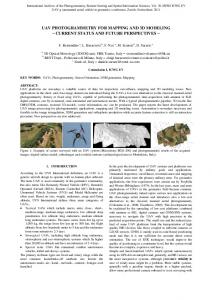
Abstract. Hardware in the Loop (HIL) Simulator is an important step in system design & development. In the present work, a lateral and longitudinal control system for Unmanned Aerial Vehicle (UAV) target was designed and implemented in a dedicated platform. Then, the X-Plane flight simulator is used to test and to validate the controllers designed. Therefore, the controllers to be implemented in the hardware can be rapidly reconfigured and optimized before this hardware is embedded on the vehicle, which makes the development and evaluation of UAV autopilot controllers easier. Presently this technology is used in aerospace engineering area as one method to test the flight guidance and control system in which reliability and high performance is demanded. Also, a Ground Control Station (GCS) was developed to receive telemetry data from the navigation system of the virtual unmanned aircraft available in X-Plane and to transmit the data reference for the closed loop control implemented in dedicated hardware. The data link transmission between the dedicated hardware and the GCS is established using XBee® RF modules. The HIL simulator system developed has the ability to simulate aircraft flight characteristic, sensor modeling and actuator modeling while communicating in real time with the lateral and longitudinal autopilot hardware. HIL simulation can be used to test the lateral and longitudinal autopilot hardware reliability, test the closed loop performance of the overall system and tuning the control parameter. By rigorous tests in the HIL simulator, the risk in the field trial can be minimized. The autopilot has a total of six control loops, pitch, altitude, vertical speed and forward speed for longitudinal control and roll and direction for lateral control. The dedicated platform consists of a microcontroller board, which hosts the digital autopilot. The interconnection between the dedicated hardware and the X-Plane flight simulator running in a PC is made through UDP data communication bus. The Ground Station allows the user to define the reference of autopilot control loop, to tune the gains of all controllers on-line and receive the data navigation from the UAV target via RF modules interface, visualizing these data in graphics. The results presented here were obtained from the digital autopilot used in closed loop control implemented in a microcontroller board, using as reference parameters values adjusted in the Ground Control Station. Keywords: Lateral and Longitudinal Autopilot, UAV, Hardware in the Loop, X-Plane flight simulator. 1. INTRODUCTION Unmanned aerial vehicles (UAVs) have recently aroused great interest in industrial and academic circles, because they have potential military and civil applications as well as scientific significance in academic research. UAVs are capable of carrying out work where the surrounding environment is dangerous or difficult to human beings and they can be utilized as platforms with maneuverability and versatility for pure academic research (Gimenes, Silva, Reis and Oliveira, 2008) and (Hing and Oh, 2009). For small UAVs the limited payload constraint impedes the use of high performance avionics systems, equipped with complete inertial and air data sensors. A successful certification of a new autopilot can only be enabled by extensive flight testing to debug both the hardware and the software before deploying the UAV in the field. Despite the necessity of real flight tests, simulation-based testing also plays a very important role. It can save time and effort prior to conduct actual flight tests. In particular, hardware in the-loop (HIL) simulation tests should be adopted whenever possible to validate together both the hardware and the software under realistic conditions (Bin and Justice, 2009) and (Tanwer, Hussain and Reel, 2010) The developed Hardware in the loop (HIL) simulator system has the ability to simulate aircraft flight characteristic, sensor modeling and actuator modeling while communicating in real time with the autopilot hardware. Hardware in the loop (HIL) simulator simulates a process such that the input and output signals show the same time-dependent values as the real dynamically operating components. This makes it possible to test the final embedded system under real working conditions, with different working loads and in critical/dangerous situations. The chosen simulation software for HIL simulator development was X-Plane (Adiprawita, Ahmad and Semibiring, 2007).
Proceedings of COBEM 2011 Copyright © 2011 by ABCM
21st Brazilian Congress of Mechanical Engineering October 24-28, 2011, Natal, RN, Brazil
This article describes a complete simulation environment which has been developed for testing and validating UAV lateral and longitudinal control systems. The details for building a comprehensive HIL simulation to test digital autopilot are presented. The remote autopilot consists of a microcontroller board, which hosts the digital autopilot and a PC running the commercial X-Plane flight simulator. The two components are interfaced via Ethernet (TCP/IP) using UDP protocol. With this set-up, autopilot prototypes can be tested with X-Plane’s sophisticated flight and atmospheric models. The data navigation from the UAV target used in X-Plane is transmitted to the Ground Control Station through the data link established by XBee® RF modules. Besides, the tuned gains of controllers and the data references for closed loop control are transmitted from Ground Station Control to digital autopilot implemented in the hardware dedicated. The HIL simulation environment allows not only testing the hardware and software but also conducting simulated flight tests with minimal cost and effort. 2. PROBLEM STATEMENT The autopilot control system is composed of a longitudinal control for controlling the altitude, forward speed, vertical speed and pitch attitude and a lateral control for controlling the direction of the airplane along with a bank angle control. Figure 1 represents the block diagram overview of the 5 DoF (Degree of Freedom) flight control system. It also shows the tasks done by PC host, running the X-Plane Simulator and by the dedicated microcontroller, running the digital autopilot controllers. Therefore, the controllers to be implemented in the hardware can be rapidly reconfigured and optimized before this hardware is embedded on the vehicle, which makes the development and evaluation of UAV autopilot controllers easier (Frutiger and Kim, 2003) and (Santos and Oliveira, 2009).
Figure 1. Lateral and Longitudinal Autopilot Controller Architecture. In Figure 1, the aircraft controllers are split into longitudinal (yellow blocks) and lateral (red blocks) controllers. The longitudinal controllers are responsible for regulating the aircraft’s forward speed, climb rate and altitude. The autopilot makes changes in vertical speed and altitude by changing the pitch angle after control the engine thrust (Nelson, 1998). Thus, we have at the heart of the longitudinal control the pitch controller. It controls the elevator angle to achieve a desired reference pitch angle. However, the user/pilot doesn’t have the ability to command pitch directly using the pitch controller. It is merely used as an inner loop for the vertical speed and altitude controllers. Also, the user can not command roll directly using the roll controller, it’s only possible by the use of the direction controller. During a climb or descent, the vertical speed controller will switch over to the altitude controller when the actual altitude gets close to the target altitude. The forward speed loop control uses the current airspeed, in feet/s, from the sensor and a PID controller to generate the control command which is sent to the throttle servo. In addition, the vertical speed and altitude hold outer control loops use the pitch attitude and pitch rate feedback, in degree and radian/sec, respectively, and two gains as inner loop control to generate the control command which is sent to the elevator servo from UAV target (Santos, 2009).
21st Brazilian Congress of Mechanical Engineering October 24-28, 2011, Natal, RN, Brazil
Proceedings of COBEM 2011 Copyright © 2011 by ABCM
The lateral control is used to hold the aircraft stable along the lateral axis. In other words, to control the lateral motion for maintaining desired heading. The yaw outer loop control uses the current magnetic heading, in degree, from the AHRS (Attitude and Heading Reference System) of virtual UAV and a PID controller to generate the control command used by bank angle control. Thus, the bank angle control inner loop uses the roll attitude and roll rate feedback, in degree and radian/sec, respectively, and two gains to form the control command which is sent to the aileron servo of the UAV target. The main objective of these controllers is to make the aircraft return to its trim conditions with minimum disturbances in terms of motion (Blakelock, 1991) and (Roskam, 2001). 3. HARDWARE IN THE LOOP SIMULATION Field trial is one of the most critical steps in UAV development. When there is failure in the field trial and the airframe crash occurs, usually only minor part of the crashed UAV continues operative. So, as usually UAVs consist of relatively high priced system, the field test proved to be one of the main problems in UAV research and development. One of the solutions to minimize the effect of control system failure in field trial is Hardware in the Loop (HIL) Simulation (Santos, 2009). The HIL simulator consists of four main parts; sensors, actuators, process and autopilot hardware. The sensors simulate the UAV sensor's output data in the airframe. The actuator simulates how the UAV autopilot hardware changes the surface controls of the airplane. The process consists of dynamics model of aircraft, which simulates how the airframe will react to the input given by the UAV autopilot hardware. Finally, the autopilot hardware to run the digital autopilot controllers used to control the aircraft (Santos, 2009).
Figure 2. Hardware in the Loop Simulator. HIL simulation can be used to test the longitudinal and lateral autopilot hardware reliability, test the closed loop performance of the overall system and tune the controller’s parameter. By rigorous testing in the HIL simulator, the risk in the field trial can be minimized. 4. X- PLANE FLIGHT SIMULATOR Although there exist several simulators like Microsoft’s Flight Simulator, and Flight Gear, the X-Plane was chosen since it provides extremely accurate aerodynamic and flight models and allows for real time data to be sent into and out of the program as well as airfoil design. X-Plane has been used in the UAV research community as a visualization and validation tool for autonomous flight controllers. Differently of the Microsoft Flight Simulator, the X-Plane allows input from and output to external sources. While Flight Gear has I/O capabilities similar to X-Plane, it is not quite as stable as X-Plane and doesn’t provide the same level of support. As noted in (Santos, 2009), X-Plane provides future capabilities that unmanned aerial vehicles will need, including navigation markers, changing weather conditions, and air traffic control communication. For all these reasons, the X-Plane was chosen to be employed in HIL simulator. The X-Plane is the most comprehensive and powerful flight simulator that exist, has the most realistic flight and atmospheric model and also has the built-in capability to exchange flight parameters with external applications, via a variety of protocols available for personal computers. In addition, X-Plane includes an easy-to-use program for creating one’s own aircraft model. This provides builders of autonomous aircraft the ability to quickly create an X-Plane model of their aircraft for use with the platform. The physics model is based on a process called Blade Element Theory, which involves breaking the aircraft down into many small elements (areas) and then finding the forces on each little element many times per second. These forces are converted into accelerations which are then integrated to velocities and positions. Factors such as drag coefficients are then calculated at each one of these areas to ensure the entire plane is being affected in some way by external forces. It also results in extremely precise physical properties that can be computed very quickly during flight,
Proceedings of COBEM 2011 Copyright © 2011 by ABCM
21st Brazilian Congress of Mechanical Engineering October 24-28, 2011, Natal, RN, Brazil
resulting in a much more realistic flight model. The X-Plane accuracy of the flight model is already approved by Federal Aviation Administration (FAA), for full motion simulator to train commercial airline pilot (Santos, 2009). Figure 3 show the PT-60 radio controlled available in X - Plane flight simulator. The aircraft dynamics equations for this airplane are not provided by simulator.
Figure 3. PT-60 Radio Controlled. The PT-60 is the default radio controlled aircraft on the X-Plane Fight simulator. Based on those natures, this aircraft was chosen to be subject on this work. The X-Plane’s standard method for communicating with external autopilot hardware or other devices is User Datagram Protocol (UDP). UDP provides a minimal overhead communication method for passing data between nodes. Unlike Transmission Control Protocol (TCP), UDP is a non-guaranteed protocol and gives no assurances that data packets will arrive in order or at all. UDP is designed to minimize bandwidth usage but presents a possible problem resulting from corrupt data. Although this problem does exist and may need to be addressed in certain cases, degradation of control and simulation has been unseen in X-Plane experimentations. X-Plane is able to receive up to 99.9 data packets per second across a local network; this has an important impact on controller functionality and simulation because they require sufficient update speed to operate correctly. It should be noted that X-Plane communication packets as well as data rates are user selectable on “Setting / Data Input & Output” window available in the X - Plane flight simulator (Ribeiro, and Oliveira, 2010). Besides, data rates cannot exceed the rending speed of the simulator. Thus, the data rate was adjusted to 20 Hz. Also, rendering rates can be improved by limiting rending options in the simulator, decreasing visibility, and removing weather items such as cloud cover. The X-Plane input or output data package follows a pattern shown on Fig. 4.
Figure 4. X-Plane data package. Basically, the data is formed by a sequence of bytes that need to be properly interpreted. The X-Plane flight simulator transmits and receives data using 32 bits precision floating point format. Thus, the first four bytes of the packet shown on Figure 4 represents the characters “DATA” used to indicate that this is a data packet. The fifth byte is an internal code (I). The next four bytes represent the parameter label (L1, L2, L3, and L4). Following there are 5 sets of 4 bytes (B11, B12, B13, B14 to B51, B52, B53, B54) representing the data itself in single precision floating point. Taking each set of 4 bytes, the first bit is the sign bit. It tells whether the number is positive or negative. The next 8 bits are the biased exponent. The remaining 23 bits represents the mantissa (Ribeiro, and Oliveira, 2010). 5. IMPLEMETATION The HIL simulator developed was based on commercially available simulation software. By using this approach, the basic simulation feature doesn't have to be implemented from scratch. Thus, the HIL simulator relates with interfacing between simulation software and dedicated hardware. In the case of aircraft autopilot system development, a HIL simulator can be developed to simulate the flight characteristic of the airframe including the sensor output and the control input signal. The aircraft autopilot system can be installed with the HIL simulator to see how the overall system works as a closed loop system. Here we can tune the PID gain parameter as well as other system parameters and watch the airframe behavior in the HIL simulator. The actual autopilot hardware is placed inside the simulation loop in order to test, verify and validate the on- board digital control algorithm implemented. Three independent computer systems were used in the hardware-in-the loop
Proceedings of COBEM 2011 Copyright © 2011 by ABCM
21st Brazilian Congress of Mechanical Engineering October 24-28, 2011, Natal, RN, Brazil
(HIL) simulation as illustrated in Fig. 5. These computers systems are the flight simulation computer, the autopilot microcontroller, and the ground station computer console.
Figure 5. Hardware in the Loop Setup. The flight simulation computer has as its main feature main to simulate aircraft dynamics flight characteristic, sensor modeling and actuator modeling through the X-plane Flight simulator. The UAV available in X-Plane provide a realistic model, immersed in a standard atmospheric model and an Earth and gravity model (WGS-84). X-Plane is a flight simulator framework which has been widely used in various research environments, providing a total simulation environment of the manned and unmanned aircraft models. The X-Plane sends the simulated states and receives the data commands from the autopilot hardware at a fixed update rate to constantly refresh the virtual scenes. In the autopilot microcontroller, the autopilot functions are tested identically as in a real flight, computing control commands to each actuator. These commands are then sent to the target UAV in flight simulator in order to drive the actuator model of the control surface. Each control surface is represented as a first order system whose time constant was identified experimentally with a rate limiter and the saturation angle. Consequently, a simulation loop is built using the X-Plane Flight Simulator and the autopilot microcontroller (dedicated hardware) exchanging the simulated data between them. The ground station computer console is a user friendly interface, used to receive telemetry data from the navigation system, such as, attitude, speeds, altitude and direction of the UAV available in X-Plane. This data can be visualized in graphics plotted into the GSC. Besides, transmit the data reference for closed loop control implemented in hardware dedicated. The data link between the hardware dedicated and the GCS is established using XBee® RF modules. This GCS permit the user tuning the PID parameters on-line, in other words, the parameters of controllers can be adjusted while the flight simulation and on-board algorithm are running simultaneously, being this another important functionality of GSC developed. Thus, the HIL simulation can be used to test the lateral and longitudinal autopilot hardware reliability, verify the closed loop performance of the overall system and tuning the control parameter. The ZigBee® wireless modems used in the project are the xBee® modules from Digi. The xBee® hardware consumes an average 50 mA and can support up to 115200 bps. It was an appropriate choice because of its reasonable price, low power, small footprint, light weight, and hardware upgradeability. A higher power model can be easily dropped in the place of the current model. This also gives the user the ability to customize the range for different missions by easily replacing the wireless module. The module used is shown in Fig. 6.
Figure 6. xBee® wireless ZigBee®. The microcontroller chosen should be programmable in the standard C language. So, we initially proposed using a Cypress Semiconductor CY8C29466 PSoC family because of our past experience with this architecture and its solid C compiler. However, the lack of the digital Input/Output capabilities to allow a timely implementation of the connection to X-Plane prevented its use. Instead, we chose the Rabbit 2000 TCP/IP development kit C-Programmable
Proceedings of COBEM 2011 Copyright © 2011 by ABCM
21st Brazilian Congress of Mechanical Engineering October 24-28, 2011, Natal, RN, Brazil
Microcontroller Module. The mainly components of the hardware Rabbit 2000 TCP/IP development kit are: Microprocessor Rabbit 2000 operating in 18.4 Mhz, flash memory of 256 kbytes, SRAM data memory of 128 kbytes, Ethernet port 10BaseT, serial port RS - 232 and RS - 485, real time clock, 4 digital input, 4 digital output, 7 timers of 8 bits, watchdog and size of 11 cm x 12 cm. The microprocessor Rabbit 2000 has two options of the Integrated Development Environment (IDE), the dynamic C tool distributed by Rabbit and the WinIDE tool of Softools. These tools use C language and a debugger to the program verification, however these tools does not emulate the programs. The availability of onboard Ethernet makes it possible to communicate with X-Plane Flight Simulator using the UDP (Uniform Datagram Protocol) (Santos and Oliveira, 2009). Figure 7 shows the Rabbit microcontroller used to implement the digital autopilot controllers and the wireless network interface.
Figure 7. Digital Autopilot Hardware. The interconnection between dedicated hardware and the X-Plane flight simulator is made through data communication bus based on network protocol, Ethernet communication module (TCP/IP) and Uniform Datagram Protocol (UDP) available in both systems. The X-Plane has the built-in capability of transmitting flight parameters at a set interval over Ethernet using UDP (Uniform Datagram Protocol). UDP is well suited for our purpose because it has low overhead. Similarly, X-Plane accepts UDP packets sent to it for modifying X-Plane flight parameters, or any other exportable variable. The interface algorithm on the test platform receives UDP packets from X-Plane, extracts flight parameters from it, and passes these on to the autopilot routine, which calculates the control inputs for the next time step. It then assembles control inputs from the autopilot into a UDP packet and sends that to X-Plane. This process then repeats with the arrival of the next packet (Santos, 2009). The computational ability of the autopilot hardware is directly related to the method of control being tested. If the autopilot hardware is unable to perform the necessary calculations, then, this hardware must be changed to a more powerful one or the utilized method of control must be changed to a method with less computational efforts. This can be verified by using hardware in the loop and should be considered experimentation all in itself. Ultimately, if the researcher is unconcerned with processing capacity of the microprocessor, the controlling autopilot hardware can simply be upgraded to a machine (PC) capable of the desired computations. The Ground Control Station software was implemented using the Graphic User Interface (GUI) available in Matlab. This interface is connected with the autopilot hardware through the wireless network. It allows the user to send reference commands to the control loop and tuning on-line the controller’s gains. It also displays telemetry received from the UAV target. The telemetry includes but is not limited to pitch, roll, altitude, climb rate, airspeed and direction. Figure 8 illustrate the GCS used to tune the gains of controllers and to define the references for control loops and graphics plot of data navigations.
Figure 8. User Friendly Interface.
21st Brazilian Congress of Mechanical Engineering October 24-28, 2011, Natal, RN, Brazil
Proceedings of COBEM 2011 Copyright © 2011 by ABCM
This application was implemented to give the user a friendly tool to fine tune the control parameters through a graphical interface over the wireless network. The gains defined by user are transmitted to autopilot hardware, then, these parameters are used to update the digital PIDs in real time implemented on-board. The parameters of controllers adjusted for altitude, vertical speed, forward speed and direction control, as well as, the values tuned for the gains of the pitch and roll attitude control loop are shown in Tab. 1. Table 1. Parameters of controllers adjusted for the PT-60 radio controlled.
The HIL simulator enables the PID gain tuning based on trial end error basis. The analytical method of PID gains tuning can not to be done, because we don’t have the aircraft dynamics model, in other words, the airframe transfer function. Thus, it’s considered easier for this user to tune the PID gain on trial and error basis since airframe crash is not a problem in HIL simulator. The digital control laws should be implemented and tested into dedicated microprocessor in the standard C language. Then, in order to implement the continuous PID controller on a digital device it is necessary to convert it into a digital PID controller (Santos and Oliveira, 2009). One approach used to obtain a digital controller similar to the continuous controller with the gains as in Table 1 is implementing in the digital processor the Eq. (1) and (2). kd kd kd C (k ) = kp + kiT + e( k ) − kp + 2 e( k − 1 ) + e( k − 2 ) T T T
(1)
U (k ) = C (k ) + C( k − 1 )
(2)
Where T is the sample period used in the system, the value chosen was 50ms. 6. RESULTS The ability of sending and receiving external data allows the simulation environment replace a real experiment to save time and effort. The closed loop control performance can be verified and demonstrated by conducting virtual experiments in advance to a real flight test. As shown in figure 1, the longitudinal autopilot takes in as inputs the commanded altitude, hc, forward speed, Fsc, vertical speed, Vsc and direction, ψc. The outputs are the elevator deflection, δe, and the throttle command, δt. The vertical speed or altitude hold autopilot converts the signal error into a commanded pitch angle θc. Then, the pitch attitude gain converts pitch attitude error into a commanded pitch rate qc, which in turn is converted to the elevator command. The Forward speed autopilot converts airspeed error to throttle command.
Figure 9. Aircraft Altitude Change in Ideal World.
21st Brazilian Congress of Mechanical Engineering October 24-28, 2011, Natal, RN, Brazil
Proceedings of COBEM 2011 Copyright © 2011 by ABCM
First of all, some conditions were established for the longitudinal motion: the PT-60 radio controlled in straight and level flight condition, with vertical speed and pitch angle nearly zero and forward speed of 65 knot, is commanded to change its altitude to a desired altitude, assuming that hdesired > hactual. In an ideal world, with longitudinal control loop responding instantaneously and with perfect controllers, the expected response of the aircraft altitude (h) would be like in Figure 9. It represents graphically the behavior of this parameter, showing the condition of vertical speed (Vs), forward speed (Fs) and pitch attitude angle (θ) during the simulation of control system. Therefore, using the HIL simulation to test, verification and validation of the longitudinal control loop, the UAV response will be presented by the behavior of the four aircraft status, pitch attitude, forward speed, vertical speed and altitude. The longitudinal control loop utilize as reference value 800 ft/m to vertical speed, 65 knot to forward speed, and 3000 ft to altitude. Initially, the aircraft is controlled by vertical speed and forward speed controller. Thus, when the current altitude of UAV reached 90% of desired value, then, the switching of the vertical speed to altitude controller occurs. The UAV will be controlled by altitude controller, since that the altitude reference is not modified. Saturation routine was added into algorithm to limit the commanded pitch to +/- 5 degrees, and commanded elevator deflection to +/- 10 degrees for safety. The commanded throttle setting was saturated between 40 and 95 percent of maximum value. To altitude control it was used a PID controller. The vertical speed and forward speed controller is similar in structure. Figures 10(a), (b), (c) and (d) show the response of longitudinal autopilot for PT-60 available in X-Plane Flight simulator for the desired altitude of the 3000ft.
(a)
(c)
(b)
(d)
Figure 10. Longitudinal control of the PT-60 Radio Controlled for the desired altitude of the 3000 ft. As shown in Fig. 10, when the altitude reaches the reference input after 30 s, as illustrated in Fig. 10(c), the vertical speed and pitch attitude angle become nearly zero, as showed in Fig. 10(a) and (b). The forward speed response during the UAV control is shown in Fig. 10(d). Modifying the altitude reference to 5000 ft, another test was made. The others data reference were not modified. Figures 11(a), (b), (c) and (d) show the response of longitudinal autopilot for PT-60 available in X-Plane Flight simulator for the desired altitude of the 5000 ft.
(a)
(b)
21st Brazilian Congress of Mechanical Engineering October 24-28, 2011, Natal, RN, Brazil
Proceedings of COBEM 2011 Copyright © 2011 by ABCM
(c)
(d)
Figure 11. Longitudinal control of the PT-60 Radio Controlled for the desired altitude of the 5000 ft Figure 12 (a) shows the PT-60 during the climbing. Figure 12 (b) and (c) shows the straight and level flight after the aircraft has reached the desired altitude.
(a)
(b)
(c)
Figure 12. Climb rate and straight and level flight of the PT-60 Radio Controlled. The lateral autopilot is also shown in Figure 1. The input command to the lateral autopilot is the commanded heading, ψc. The output is the aileron command δa. The heading hold autopilot converts heading error to roll attitude command, φc. The roll attitude autopilot converts roll angle error to roll rate command, pc. The roll rate autopilot converts the roll rate error to aileron command, δa. Figures 13(a) illustrate the response of roll attitude control of the PT-60 and in figure 13(b) show the response of heading of the UAV. Note, the direction is switched of 120 to 200 degree after 28 s.
(a)
(b)
Figure 13. Lateral control of the PT-60 Radio Controlled for the desired heading of the 120 and 200 degree.
(a)
(b) Figure 14. Lateral movements control of the PT-60 Radio Controlled.
(c)
Proceedings of COBEM 2011 Copyright © 2011 by ABCM
21st Brazilian Congress of Mechanical Engineering October 24-28, 2011, Natal, RN, Brazil
Figure 14 (a) shows the PT-60 maneuvering to a desired direction of 120 degree. Figure 14 (b) illustrates the straight and level flight after the UAV has reached the desired direction of 120 degree. Figure 14(c) shows the PT-60 maneuvering to the new desired direction of 200 degree. 7. CONCLUSION Hardware in the Loop (HIL) simulation environment has been built to test, validate and verify hardware and software of digital autopilot development of a small UAV. This HIL approach enable the developer to evaluate several aspects of the UAV autopilot hardware, finding the problem, refine the firmware, test the reliability, fine tune system parameter, and many others. The HIL simulator in the UAV development is proved to be very valuable. It is also demonstrated that it is possible to find the controllers parameters for the lateral and longitudinal autopilot without using the UAV dynamics model, through an interactive ground station and a digital autopilot controller implemented in a dedicated microprocessor. The tests using using X-Plane’s UAV performed successfully as expected. The interactive process is done inside the development environment without risking the valuable airframe and payload. The small size and large number of connectivity options of the Rabbit makes it possible to remove it from the platform and use it in an actual aircraft without having to rewrite the autopilot code. The HIL simulation is an indispensable tool for performing simulated flight support tests of developed lateral and longitudinal control for small UAV with minimal cost and effort. 8. FUTURE WORKS The present HIL experiment already demonstrate the ability of using this approach in lab tests before embedding the autopilot in the aircraft to perform the field tests. Future works consist in establish a process to design, configure and test an autopilot in lab environment before the hardware be actually embedded. To achieve this aim, it will be necessary to study and compare the consistency between the models used in the development process. Nominally, these models are, a nonlinear representing the target aircraft and that shall be used to design the control loops; a X-Plane model to be used in SIF (Software in the Loop) and HIL tests. Finally, the similarity between these models and the behavior of the aircraft to be used in the field tests will be verified. With this process established, the improvement of the autopilot performance, for example changing the guidance law or the controller gains, will be done in a very straightful way. 9. REFERENCES Gimenes, R., Silva, D.C., Reis, L.P. and Oliveira, E., 2008, “Using Flight Simulation Environments with AgentControlled UAVs”, Proceedings of the 8th Conference on Autonomous Robot Systems and Competitions, Portuguese Robotics Open, Aveiro, Portugal, pp 21-26. Hing, J.T. and . Oh, P.Y., 2009, “Development of an Unmanned Aerial Vehicle Piloting System with Integrated Motion Cueing for Training and Pilot Evaluation.”, Journal of Intelligent & Robotic Systems. Vol. 54, Numbers 1-3, 17p. Tanwer, A., Hussain, M. and Reel P., 2010, “Deployable Low Cost Outdoor Aerial Surveillance System”, “International Journal of Advancements in Technology”. Vol. 1, Numbers 1, pp 131-147. Adiprawita, W., Ahmad, A.S. and Semibiring, J., 2007, “Hardware in the Loop Simulation for Simple Low Cost Autonomous UAV (Unmanned Aerial Vehicle) Autopilot System Research and Development”, Proceedings of the International Conference on Electrical Engineering and Informatics, Bandung, Indonesia, pp 218-221. Bin, H. and Justice, A., 2009, “The Design of an Unmanned Aerial Vehicle Based on the ArduPilot”, Indian Journal of Science and Technology, Vol. 2, No. 4, pp. 12–15. Frutiger, M., Kim C., 2003, “Digital Autopilot Test Platform with Reference Design and Implementation of a 2-Axis Autopilot for Small Airplanes”, Departament of Electrical and Computer Enginnering, University of illinois. Santos, S.R.B. and Oliveira, N.M.F., 2009, ”Testbed for Controllers of Longitudinal Movements of aircraft”, 20th International Congress of Mechanical Engineering, Gramdo, Brazil. Nelson, R. C., 1998, “Flight Stability and Automatic Control,” 2nd ed., McGraw-Hill. Blakelock, J. H., 1991, “ Automatic control of Aircraft and Missiles”, 2nd ed., John Wiley & Sons. Roskam, J., 2001, “Airplane Flight Dynamics and Automatic Flight Controls”, Design, Analysis and Research Corporation. Santos S. R. B., 2009, “Arquitetura de um Piloto Automático Longitudinal Hardware in the Loop com o simulador de vôo X-Plane”, Tese de Mestrado, Instituto Tecnologico de Aeronautica, São Jose dos Campos. Ribeiro, L.R. and Oliveira, N.M.F., 2010, “UAV Autopilot Controllers Test Platform using MATLAB/SIMUlLINk and X-Plane”, 40th ASEE/IEEE Frontiers in Education Conference, DC, USA. Santos, S.R.B Oliveira, N.M.F., 2009, “ Test platform to pitch angle using hardware in the loop” 39th ASEE/IEEE Frontiers in Education Conference, San Antonio, USA.