Available online at www.sciencedirect.com
ScienceDirect Energy Procedia 109 (2017) 78 – 85
International Conference on Recent Advancement in Air Conditioning and Refrigeration, RAAR 2016, 10-12 November 2016, Bhubaneswar, India
Modelling and simulation of concentrating photovoltaic system with earth water heat exchanger cooling Sanjeev Jakhar1*, M.S.Soni1, Nikhil Gakkhar2 1
Centre for Renewable Energy and Environment Development (CREED),Department of Mechanical Engineering, Birla Institute of Technology and Science, Pilani, Rajasthan, India 333031 2 Scientist B, Ministry of New and Renewable Energy, Government of India, New Delhi, India 110003
Abstract In the present paper, a novel cooling system for concentrating photovoltaic (CPV) which is termed as earth water heat exchanger (EWHE) is modeled and simulated for local conditions of Pilani, Rajasthan. The CPV temperature and power output are obtained with respect to variation in mass flow rate of fluid and concentration ratio (CR). The simulation results shows that the maximum CPV temperature goes up to 416.36 °C at 3 Suns without any cooling, while with cooling it is reduced down to 85.28 °C for the mass flow rate of 0.022 kg/s. CPV temperature drop and power output increases with increasing in mass flow rate when it operated with EWHE in a closed loop. The mass flow rate of 0.022 kg/s is estimated as suitable flow rate as it may be used for the practical applications. It is also observed that with increase in mass flow rate the outlet temperature of CPV/T decreased. © Published by by Elsevier Ltd.Ltd. This is an open access article under the CC BY-NC-ND license © 2017 2017The TheAuthors. Authors. Published Elsevier (http://creativecommons.org/licenses/by-nc-nd/4.0/). Peer-review under responsibility ofthe organizing committee of RAAR 2016. Peer-review under responsibility of the organizing committee of RAAR 2016. Keywords:Concentrating Photovoltaic; Earth Water Heat Exchanger; TRNSYS (v17.0); Modelling.
1. Introduction Among various renewable energy sources, Solar energy has a huge potential to overcome energy demand, due to its abundant availability [1-2]. The energy from the sun can be harnessed in the form of either heat, like solar thermal, or electricity like photovoltaic (PV) and is termed as clean energy. PV technology is quite mature
* Corresponding author. Tel.: +91 1596 516455; fax: 91 1596 244183. E-mail address:
[email protected],
[email protected]
1876-6102 © 2017 The Authors. Published by Elsevier Ltd. This is an open access article under the CC BY-NC-ND license (http://creativecommons.org/licenses/by-nc-nd/4.0/). Peer-review under responsibility of the organizing committee of RAAR 2016. doi:10.1016/j.egypro.2017.03.054
Sanjeev Jakhar et al. / Energy Procedia 109 (2017) 78 – 85
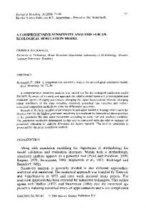
technology and enjoys long and wide field experiences all over the world [3-5]. However, with the requirement of large area of the PV, the cost of this technology is still on the higher side when compared with traditional power generation sources. The generation cost of SPV can be minimized if the smaller area is used for same power output. This can be done by using concentrating photovoltaic (CPV) in which solar radiation is concentrated with the help of mirrors or lenses to focus the sunlight on a smaller area [6]. Such systems are classified according to the number of times, the radiation is focused to a particular point, which is termed as Concentration Ratio (CR) and usually referred as 'Suns'.[7]. But the main problem with the CPV system is that with increase in CR, the cell temperature increases and this temperature growth leads to reduction in the cell efficiency and may damage the cell’s integrity. If the temperature increased to a certain limit the cell's life-span would reduce rapidly [8-9], so proper cooling system is required to maintain the temperature within the limits. Many researchers have worked on various CPV cooling techniques. When PV cells are coupled with thermal collectors so that the concentrated solar energy can produce both thermal and electrical power, the system is termed as concentrating photovoltaic/thermal (CPV/T) systems [10-11]. Such technology has been discussed in the literature for various applications, like water heating [12], air heating [13], desalination [14] etc. Coventry [15] investigated the performance of a CPV/T collector where the row of cells were cooled by fluid flowing through an aluminum tube which has finned internally. Renno and Petito [16] presented a research on domestic application based CPV/T system which works on 900 Suns. They obtained the CPV/T outlet temperature as 90 °C which can be used to run an absorption heat pump for cooling during summer period. Helmers et al. [17] presented an energy balance model for the CPV/T system. They found that for higher CR, the electrical efficiency increases and the thermal losses decreases. Mittelman et al. [14] proposed a coupled system of multiple effect evaporation with CPV/T to generate both electric power output and desalinated water. The cooling of CPV cells can be achieved by coupling it with geothermal cooling system. Geothermal cooling works on the concept that at a certain depth, the soil temperature remains almost constant throughout the year and is approximately equals to the mean surrounding temperature over a year. So the soil can be used as a thermal sink for the cooling of CPV/T system[18]. Various researchers have used earth water heat exchanger (EWHE) and earth pipe air heat exchanger for air conditioning using water and air as a cooling medium respectively [19-22]. The EWHE pipes are buried below the ground to a particular depth, and the inlet of the pipes carries the hot water which transferred the energy from the high temperature fluid to the soil, thus resulting in the decrease in outlet temperature [23-25]. The present research work deals with the utilization of geothermal cooling principle for the removal of waste heat of CPV/T thus providing a new cooling technique. The objective of this paper is to provide transient investigation of coupled CPV/T and EWHE system using TRNSYS (v17.0) by modelling and simulation for peak summer duration of Pilani, Rajasthan. 2. Modelling and simulation of CPV/T system with EWHE The proposed system is modeled and simulated for the Pilani region of Rajasthan, India using TRNSYS software. TRNSYS is a transient analysis simulation tool for the study of renewable energy systems [26]. The simulation of CPV/T coupled with EWHE requires climatic data such solar radiation, wind velocity, ambient temperature, relative humidity etc. Weather data for Pilani, Rajasthan (India) have been generated using inbuilt Meteonorm files provided within TRNSYS. Soil properties like density and thermal conductivity have been determined using available testing standards. The simulation model consists of components (called as Types) which are inbuilt and can be linked to other Types and takes time dependent inputs and technical parameters to give transient output. Fig. 1 represents the simplified flow diagram for the coupled system under consideration for this research.
79
80
Sanjeev Jakhar et al. / Energy Procedia 109 (2017) 78 – 85
Output
Simulation summary
Weather data processor (TMY)
System sizing parameters
Printer
CPV/T collector
Controller
Variable speed pump
EWHE
Output Fig.1.TRNSYS information flow diagram for the CPV/T with EWHE cooling.
As shown in Fig.1 the component for the CPV/T is connected to pump (Type 3), which is further connected to EWHE to make it as a close loop. CPV/T is a hybrid collector which produces both electrical and thermal energy. Within the ground heat pump library of TRNSYS, EWHE is a horizontal heat exchanger model which interacts thermally with the ground. It considers convection within the tunnel and conduction to the soil. In the closed loop simulation, the excess waste heat of CPV/T is dissipated to the soil by EWHE. Furthermore, weather data component (Type 15) is connected with CPV/T to provide the climatic data of the local conditions. For the simulation, the physical and thermal parameters of the system taken are shown in Table 1. Table1. Physical and thermal parameters used in simulation. Parameters
Properties
CPV/T collector area
5 m2
Thermal conductivity of absorber plate
385 W/m K
Absorber plate thickness
0.002 m
Copper tube diameter (OD)
0.012 m
CPV panel reference temperature
25 °C
CPV/T collector thickness
0.04 m
Insulation conductivity
0.045 W/mK
Back Insulation thickness
0.05 m
Edge Insulation thickness
0.025 m
Concentration ratio (CR)
2 to 6
High Density Polyethylene (HDPE) pipe thermal conductivity
0.40 W/mK
Fluid density
1000 kg/m3
Sanjeev Jakhar et al. / Energy Procedia 109 (2017) 78 – 85
3. Results and discussion The simulation of the proposed system ran for 10 hours, which is mean sunshine hours during peak summer period (June 21). The performance of the EWHE was calculated for the pipe length of 90 m at the burial depth of 3.5 m, where uniform soil temperature is maintained throughout the year. The parametric variation is carried out for different mass flow rate, CR and power output.
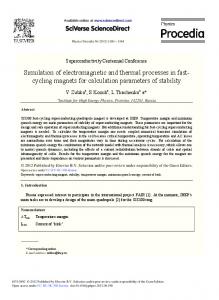
Fig.2. CPV panel temperature with cooling and without cooling for various mass flow rates (Suns=3).
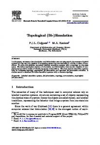
The temperature variation of CPV panel for different mass flow rates in case of cooling and without cooling is shown in Fig. 2. It is observed that the temperature of CPV panel ranges from 122.48 °C to 416.36 °C with 3 Suns in case of without cooling when there is no flow. With EWHE cooling scenario, the CPV panel temperature decreases drastically and it varies between 64.71 °C - 128.51°C, 43.43 °C - 91.40 °C, 38.49 °C- 79.87 °C and 37.05 °C- 76.48 °C for mass flow rates of 0.006 kg/s, 0.018 kg/s, 0.026 kg/s and 0.03 kg/s respectively. It shows that with increase in the mass flow rate, the CPV temperature decreases. The maximum temperature drop is observed for 0.03 kg/s and it remains almost constant for flow rate of 0.026 kg/s and 0.022 kg/s. Since 0.03 kg/s is high flow rate that is high pumping power, so 0.022 kg/s may be selected for the practical applications as the temperature variation in these three flow rates are almost similar. When the simulation is carried out for the 3 suns, with the simulation time of 10 hour duration, it is observed that in case of without cooling there is no CPV power output from 9 am to 5 pm due to high cell temperature. However the power is obtained for simulations of early morning (8 am) and late evening (6 pm). The CPV power output for same CR with different mass flow rates in case of EWHE cooling is shown in Fig. 3. It is found out that in case of EWHE cooling the CPV produces power for the entire simulation duration. For the flow rate of 0.022 kg/s, the power output varies from 137.98 W to 722.43 W. It is also observed that the CPV power gradually increases as mass flow rate increases. However during the peak hours the lower mass flow rates (0.006 kg/s, 0.01 kg/s) experiences lesser power output. The reason for the same is that they carried away less heat and thus resulting is less CPV temperature drop. This causes the variation in CPV power for lower and higher flow rates with peak output obtained at 1400 hrs for later case.
81
82
Sanjeev Jakhar et al. / Energy Procedia 109 (2017) 78 – 85
Fig.3.CPV power output with cooling for different mass flow rates (Suns=3).
For the mass flow rate of 0.022 kg/s, the effect on the performance of CPV for the CR varying from 2 to 6 Suns is estimated. The results are shown in Fig.4 and Fig.5. It is observed that with increase in CR the maximum CPV temperature varies from 290.68 °C to 793.39 °C for CR variation of 2 to 6 respectively in case of without cooling at 1400 hrs. Similarly it decreases with EWHE cooling and ranges between 36.79 °C - 72.53 °C, 43.92 °C - 95.49 °C and 50.97 °C - 117.12 °C for 2 Suns, 4 Suns and 6 Suns respectively.
Fig.4. CPV temperature without cooling for different concentration ratios.
Sanjeev Jakhar et al. / Energy Procedia 109 (2017) 78 – 85
Fig.5. CPV temperature with cooling for different concentration ratios (flow rate=0.022 kg/s).
As discussed earlier, CPV does not produces power without any cooling for CR of 2 to 6 Suns due to fact that CPV power depends on the operating temperature and without cooling the temperature is very high. The CPV power with cooling for different CR is shown in Fig. 6. It is observed that the power output is of the range from 134.15 W665.29 W, 140.59 W- 714.18 W and 145.24 W - 749.64 W for 2 Suns, 4 Suns and 6 Suns respectively. Thus, it is clearly seen that the high CR is beneficial for CPV cells but at the same time the cooling is essential.
Fig.6. CPV power output with cooling for different concentration ratios (flow rate=0.022 kg/s).
The variation of CPV/T water outlet temperature at 3 Suns for different mass flow rates is shown in Fig. 7. It is observed that the outlet temperature of CPV/T decreases with increase in mass flow rate, as expected. The outlet
83
84
Sanjeev Jakhar et al. / Energy Procedia 109 (2017) 78 – 85
temperatures obtained after six hours of simulation (i.e. 1400 hrs) are 80.23 °C for 0.006 kg/s and 62.10 °C for 0.026 kg/s respectively. Moreover Fig. 7 depicts that the temperature difference between 0.022 kg/s and 0.026 kg/s flow rates is merely 1.9 °C for the same conditions. Considering the small variation in temperature for these flow rates, it can be concluded that the 0.022 kg/s flow rate may be sufficient for CPV/T system with 3 Suns. From the Fig. 2 and Fig. 7 it is also observed that the temperature of CPV cells is higher than CPV/T water outlet temperature with different mass flow rates which makes it possible to cool the CPV cells.
Fig.7. CPV/T water outlet temperature for different mass flow rates (Suns=3).
4. Conclusion The current research discusses the transient thermal analysis of CPV/T with EWHE coupled system for the local conditions of Pilani, Rajasthan. The model of combined system has been designed and simulated in the TRNSYS (v17.0) for ten hour operation during peak summer day (21 June). For the simulation, the parametric variation is carried out for difference cases of with and without cooling. The variation in mass flow rate and CR has been done to estimate the CPV power output and cell temperature. The simulation results show that at 3 Suns, the maximum CPV temperature goes up to 416.36 °C without any cooling. With EWHE cooling, the CPV temperature decreases drastically to 85.28 °C for the mass flow rate of 0.022 kg/s. The mass flow rate of 0.022 kg/s is considered to be optimum flow rate and it may be used for the practical applications. For a constant CR the simulation results of CPV power output with different mass flow rates shows that in case of EWHE cooling, the CPV produces significant power output for the entire simulation time. However, in case of no cooling, the CPV doesn't produce any power during peak summer, due to very high cell temperature. It is also observed that the CPV power gradually increases as mass flow rate increases. The effect of different CR on the performance of CPV is estimated for a stipulated flow rate of 0.022 kg/s. The results show that with increase in CR the maximum CPV temperature increases from 290.68 °C to 793.39 °C for CR variation of 2 to 6 respectively. The cell temperature decreases significantly with the help of EWHE cooling. In the end, the variation of CPV/T water outlet temperature at 3 Suns for different mass flow rates shows that as the mass flow rate increases, the outlet temperature of CPV/T decreases. The simulation of CPV/T with EWHE shows the positive improvement in the system. Such system may be applicable to western Rajasthan which is arid region and receives high solar insolation for more than 325 days in a year. This system will be very much helpful in summer as outside temperature reach up to 50 °C, leaving very little
Sanjeev Jakhar et al. / Energy Procedia 109 (2017) 78 – 85
room for consumption of thermal energy. The excess waste heat, thus easily dissipated with the help of geothermal principle. Acknowledgements Authors gratefully acknowledge the support from the Center for Renewable Energy and Environment Development, Birla Institute of Technology and Science, Pilani, Rajasthan, for this research. References [1] Gakkhar N, Soni MS, Jakhar S. Second law thermodynamic study of solar assisted distillation system: A review. Renew Sustain Energy Rev 2016;56:519–35. [2] Soni MS, Gakkhar N. Techno-economic parametric assessment of solar power in India: A survey. Renew Sustain Energy Rev 2014;40:326– 34. [3] Würfel P, Würfel U. Physics of Solar Cells: From Basic Principles to Advanced Concepts. John Wiley & Sons; 2009. [4] Solanki C, Sangani C, Gunashekar D, Antony G. Enhanced heat dissipation of V-trough PV modules for better performance. Sol Energy Mater Sol Cells 2008;92:1634–8. [5] Jakhar S, Soni MS, Gakkhar N. Performance Analysis of Photovoltaic Panels with Earth Water Heat Exchanger Cooling. MATEC Web Conf 2016;55:1–6. [6] Jakhar S, Soni MS, Gakkhar N. Historical and recent development of concentrating photovoltaic cooling technologies. Renew Sustain Energy Rev 2016;60:41–59. [7] Pérez-Higueras P, Muñoz E, Almonacid G, Vidal PG. High Concentrator PhotoVoltaics efficiencies: Present status and forecast. Renew Sustain Energy Rev 2011;15:1810–5. [8] Royne A, Dey CJ, Mills DR. Cooling of photovoltaic cells under concentrated illumination: a critical review. Sol Energy Mater Sol Cells 2005;86:451–83. [9] Al-Amri F, Mallick TK. Alleviating operating temperature of concentration solar cell by air active cooling and surface radiation. Appl Therm Eng 2013;59:348–54. [10] Sonneveld PJ, Swinkels GL a. M, Tuijl B a. J Van, Janssen HJJ, Campen J, Bot GP a. Performance of a concentrated photovoltaic energy system with static linear Fresnel lenses. Sol Energy 2011;85:432–42. [11] Kolhe M, Bin D, Hu E. Water Cooled Concentrated Photovoltaic System. Int J Smart Grid Clean Energy 2012;2:2–6. [12] Zhang L, Jing D, Zhao L, Wei J, Guo L. Concentrating PV/T Hybrid System for Simultaneous Electricity and Usable Heat Generation: A Review. Int J Photoenergy 2012;2012:1–8. [13] Hegazy AA. Comparative study of the performances of four photovoltaic/thermal solar air collectors. Energy Convers Manag 2000;41:861– 81. [14] Mittelman G, Kribus A, Mouchtar O, Dayan A. Water desalination with concentrating photovoltaic/thermal (CPVT) systems. Sol Energy 2009;83:1322–34. [15] Coventry JS. Performance of a concentrating photovoltaic/thermal solar collector. Sol Energy 2005;78:211–22. [16] Renno C, Petito F. Design and modeling of a concentrating photovoltaic thermal (CPV/T) system for a domestic application. Energy Build 2013;62:392–402. [17] Helmers H, Bett AW, Parisi J, Agert C. Modeling of concentrating photovoltaic and thermal systems. Prog Photovoltaics Res Appl 2014;22:427–39. [18] ASHRAE. Handbook of application. Atlanta Ga. American Society of Heating Refrigerating and Air Conditioning engineers Inc., 1985. [19] Jakhar S, Misra R, Bansal V, Soni MS. Thermal performance investigation of earth air tunnel heat exchanger coupled with a solar air heating duct for northwestern India. Energy Build 2015;87:360–9. [20] Jakhar S, Misra R, Soni MS, Gakkhar N. Parametric simulation and experimental analysis of earth air heat exchanger with solar air heating duct. Eng Sci Technol an Int J 2016;19 (2):1059-1066. [21]Bansal V, Misra R, Agrawal G Das, Mathur J. Performance analysis of earth–pipe–air heat exchanger for summer cooling. Energy Build 2010;42:645–8. [22] Sodha MS, Sharma AK, Singh SP, Bansal NK, Kumar A. Evaluation of an earth—air tunnel system for cooling/heating of a hospital complex. Build Environ 1985;20:115–22. [23] Jakhar S, Soni MS, Gakkhar N. Parametric modeling and simulation of photovoltaic panels with earth water heat exchanger cooling. Geothermal energy 2016; 4:10. DOI 10.1186/s40517-016-0054-8. [24] Chel A, Janssens A, Paepe M De. Thermal performance of a nearly zero energy passive house integrated with the air – air heat exchanger and the earth – water heat exchanger. Energy Build 2015;96:53–63. [25] Joen, Christophe T, Liu Liping PD me. Comparison of Earth-Air and Earth-Water Ground Tube Heat Exchangers for Residentialal Application. Int. Refrig. Air Cond. Conf. Purdue Univ., 2012, p. 2194–10. [26] TRNSYS 17: Transient System Simulation Program, University of Wisconsin, Madison.
85