Abstract - In the present paper a complete model of the self-controlled synchronous motor considering the variable saturation effects is presented. This effects is ...
MODELLING AND SIMULATION OF SELFCONTROLLED SYNCHRONOUS MOTOR CONSIDERING SATURATION Vasile Manoliu, Dragos Ovidiu Kisck Depart. of Electrical Machines and Drive Systems, Faculty of Electrotechnics, University “POLITEHNICA” of Bucharest, Splaiul Independentei 313 - 77206, Bucharest, Romania Abstract - In the present paper a complete model of the self-controlled synchronous motor considering the variable saturation effects is presented. This effects is considered by determining some computing specific inductances for an operating point of saturated region of magnetic characteristic. Two sets of differential equations is developed in d - q frame, one for conduction state, and the other for the commutation state. Using two auxiliary variable angles, only the two sets of equations describes all 12 sequences of operation. The correlation between these variable angles and the rotor angle of position is established by calculating the static torque using the Finite Element package FLUX2D[1]. The model is able to determinate the damper currents and torque variations, and the influence of the damper resistances variations upon d.c. and field currents and upon electromagnetic torque. Keywords: synchronous motor, self-control, modelling, simulation
1. INTRODUCTION
2. PRINCIPLES OF MODELLING
In the evaluating of transient performances of an synchronous motor associated with current source inverter, an integral system of equations must be realised, which include the interactions machine-converter for both, conduction and commutation periods, in the thyristors. Self-controlled synchronous machine modelling has been developed by many authors, but most of them assume that magnetic saturation effects can be neglected. Because the achievement of the valid model for an great extent of operation, in which the nonlinearities dues of saturation can be considered is practical impossible, the saturation effects is appreciated by means of some computed inductances [2], for an operating point described by its co-ordinated situated on the saturated portion of magnetic characteristic. Field analysis using FLUX2D allows determination of firing instants of inverter thyristors by the condition of producing a maximum average torque. We compute static torque using the “moving airgap” feature of FLUX2D. FLUX2D allows the determination of synchronous and subtransient parameters, and, also, the evaluation of degree of saturation for synchronous inductances. Based on the d-q model for the self-controlled synchronous motor considering the effects of magnetic saturation, using the design and calculated parameters for a experimental drive system, it was realised a simulation program which allows the representation of unmeasurable variations of ones quantities, such as: damping winding currents and electromagnetic torque.
For an saturated machine cannot be used some of main assumptions used in derivation of synchronous machine equations, such as: sinusoidal distribution of the field in the airgap, linearity of relationship between field and magnetisation current. Many authors have dealt global the problems in magnetically saturated region, or uses the approximates methods to improve the influence of saturation upon the q-parameters. A much simpler and faster, but less accurate approach, is to assume that only certain inductances in the equivalent circuits saturate. Following this approach, it is usual to assume that the stator and rotor winding leakage inductances have constant values. This implies that only mutual flux path are subject to saturation, thereby affecting Lmd and Lmq. In a previous paper [4] the magnetic saturation property of a synchronous motor was characterised with magnetic permeance, which is determined through the relation between the induced back electromotive force and the field current obtained from no-load saturation curve of the motor. Noted that, the no-load saturation curve obtained experimental not expresses the global saturation effects, describing the effects of saturation in direct-axis only. In this paper we suppose that a variable saturated machine can be considered as a machine having a fictitious variable airgap function of the magnetisation current; the presence of iron determine a proportionality between the saturation level and the equivalent airgap. Thus, a salient pole machine can be replaced with a equivalent machine, having constant airgap and the same non-saturated inductances Ld and Lq.
By defining the magnetisation currents:
imd id i ' f i 'D ;
(1)
imq iq i 'Q
where all currents is referred to stator, can be expressed: a global magnetisation current[2]: 2 2 im imd ( Ld / Lq ) imq
(2)
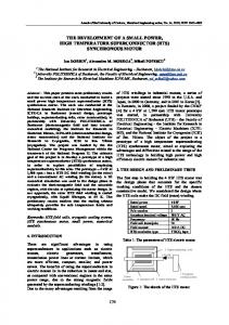
The 4-pole synchronous machine studied, of inversely construction, has an outer diameter of 316 mm and a stack length of 100 mm. The rotor circuit has a 3-phase 2layer winding disposed in 27 slots. Due to the fractional slot number, the motor cannot be modelled over one pole pitch; therefore, the entire motor must be modelled. Figure 1 shows the cross section of the motor.
and the flux through all the windings in the d and q axes: md Lm (im ) imd ; mq Lm (im ) ( Ld / Lq ) imq (3) the “inductance” Lm depending of the global magnetisation current of machine, because the real machine have a variable airgap. Considering the no-load saturation curve obtained experimental as d-axis saturation curve, the saturation curve for the quadrature axis can be calculated as:
mq ( Lad / Laq imd ) Laq / Lad md (imd )
(4)
where the inductances (LadLmd; LaqLmq) have nonsaturated values. By the magnetisation characteristic of machine can be expressed: Lm=md /imd and incremental inductance: (5) L d ( Lm im ) / dim Thus can be calculated the “self” inductances:
L'd L cos2 Lm sin2 ; L'q L sin2 Lm cos2
(6)
and the “mutual” inductance:
L'dq L'qd ( L Lm ) sin 2 / 2 Lq
which depend, by angle arctg
(7)
i mq of Ld i md
Figure 1. Cross-section of the synchronous motor
The variations of inductances Ld and Lq with stator current was calculated; from the representations of this dependencies, in p.u., (figure 2.) the influence of magnetic saturation, dues of current is upon the synchronous inductances values can be seen (the magnetic saturation affect much more the d-axis parameters than those of q-axis). Thus, for a current variation between 0,1 and 1, ld decrease with 6,63%, and lq decrease with 1,2%.
saturation level of machine. Thus, in a d-q model, the magnetic interaction between axes can be considered.
3. FIELD ANALYSIS USING FLUX2D Most studies was reported in literature considering constant values for parameters, writing equations in the dq variables. However, in the self-controlled synchronous motor operation, the synchronous inductances varies with currents due of saturation effects and the commutation inductance is, also, variable being calculated in terms of subtransient inductances and the leading angle of commutation. Using the Finite Element package FLUX2D, using a magnetostatic application was determined the inductances Ld and Lq; afterwards, using a Standstill Frequency Response (SSFR) test simulation was calculated Ld and Lq and, also, the subtransient inductances L”d and L”q, for unsaturated and saturated conditions. Based on this approach, it was obtained that the subtransient inductances is less affected by saturation; also, without damper cage, is obtained increased values for these inductances (for example, for L” d the value increase with 18%).
Figure 2. The variation of inductances with stator current
In a classical self-controlled synchronous motor, the torque is driven by the currents in the stator windings, and these currents depend on the rotor position. Since the stator phases are wye-connected, the static torque generated by two stator phases connected in series and powered with a constant current offers sufficient information to design a suitable current control strategy. For calculation of static torque using FLUX2D, we used a conventional circuit analysis method to assemble the magnetic potential equations and the current and voltage
equations for each conductor. Non-linear properties are taken into account using the Newton-Raphson algorithm and a conjugate gradient method is used to solve the system at each time step. The on and off states of thyristors are modelled using a resistance with a low value (on state) or high value (off state). With a circuit structure of figure 3, by magnetostatic simulation in FLUX2D, the variation of static torque shown in figure 4, for if = 4A and constant armature current (10A), is obtained.
Figure 5. Structure of complete circuit for static torque simulation
Figure 6. Static torque maximised Figure 3. Structure of circuit for static torque simulation
From the static torque waveform (fig. 4) we determine the sequence of switching of the inverter thyristors: depending on the rotor position, the thyristors are turned on and off, for each 60 electrical degrees rotation, to produce a maximum average torque.
Based on this informations, and considering the leading angle of commutation as x0, we conclude that the correlation between firing instants of thyristors and the leading angle x0 (which is related to rotor position) is that expressed in Table 1. Table 1
Thyristor to be fired T1 and T2 T2 and T3 T3 and T4 T4 and T5 T5 and T6 T6 and T1
Rotor position 0 /2 - x0 5 /6 - x0 7 /6 - x0 3 /2 - x0 11 /6 - x0 /6 - x0
4. RESULTS OF SIMULATION CONSIDERING SATURATION
Figure 4. Static torque (two phases in series)
With a circuit structure of figure 5, considering the lowvalue of equivalent resistance of thyristor for on-state: 10m, respectively, for off-state: 100000, the variation of maximised static torque is obtained; it is shown in figure 6, for specified currents.
PROGRAM
The self-controlled synchronous motor system equations have been solved by means of a computer program, writing in Turbo Pascal, based on a fourth order RungeKutta-Gill method. Using the procedure describes in [2], and introducing the auxiliary variable angles: 1 for conduction and 1 for commutation, the six periods for conduction is reduced to only one, and, also, the six periods for commutation is reduced to only one. The correlations between rotor osition angle, , and auxiliary angles 1 and 1 is shown in Table 2. Both for conduction and commutation sequences as state variable is used the rotor winding currents if, iD, iQ and the speed (in p.u.). Furthermore, for
conduction period is used the d.c. link current i0, and for commutation period - the currents id and iq.
The electromagnetic torque is expressed as function of currents and of auxiliary angles: 1 (conduction) and 1 (commutation). Table 2
Commutation
Conduction
Sequence T2 &(T1T3)
[5/6-x0 ; 5/6-x0+]
1 - /3
T3 & (T2-T4)
[7/6-x0 ; 7/6-x0+]
- 2/3
T4 & (T3-T5)
[3/2-x0 ; 3/2-x0+]
-
T5 & (T4-T6)
[11/6-x0 ;11/6-x0+]
- 4/3
T6 & (T5-T1)
[/6-x0 ; /6-x0+]
- 5/3
T1 & (T6-T2)
[/2-x0; /2-x0+]
The simulation program realised allows the representation of unmeasurable variations of ones quantities, such as: damping winding currents and electromagnetic torque. In figures 7 and 8 the simulated waveforms of currents and electromagnetic torque for no-load starting process, and leading angle x0 = /4 is represented.
Figure 7. D.c. link and damper windings currents (t - 1s/div.;i - 1p.u./div.)
Figure 8. Field current and electromagnetic torque (t - 1s/div.; m, i - 0.5p.u./div.)
1
T2 & T3
[5/6-x0+ ; 7/6-x0]
-
T3 & T4
[7/6-x0+ ; 3/2-x0]
- 4/3
T4 & T5
[3/2-x0+ ; 11/6-x0]
- 5/3
T5 & T6
[-/6-x0+ ; /6-x0]
T6 & T1
[/6-x0+ ; /2-x0]
- /3
T1 & T2
[/2-x0+ ; 5/6-x0]
- 2/3
Sequence
The motor rated values is: PN = 3.2 kW; UN = 220 V; IN = 12.35 A; nN = 1500 rpm.
5. CONCLUSIONS A method of including saturation in the d-q axis model of a synchronous machine is proposed. The parameters are related to the slope and change in slope of the magnetisation characteristic which describe the saturation function. By expressing the association machine-converter equations in a d-q model incorporating magnetic saturation, is avoided to write the equations of the association for each converter topology by using the parameters defined in the phases frame. A useful application of FLUX2D in determination of realistic values of parameters and calculation of static torque of synchronous motor is, also, realised.
6. REFERENCES [1] ***** - FLUX2D - Finite element software for electromagnetic applications; Version 7.20; CEDRAT (CEE), MAGSOFT (USA),1997. [2] I. Iglesias, L. Garcia-Tabares, J. Tamarit - “A d-q model for the self-controlled synchronous machine considering the effects of magnetic saturation”, IEEE Trans. on E.C., vol. 7, 1992, pp. 768-775. [3] L. Pierrat - “Models unification for the saturated synchronous machine”, Proc. I.C.E.M.A. - S.M. Conference, Zurich, 1991, vol. 1, pp. 44-48; [4] V. Manoliu - "Performance and operation of selfcontrolled synchronous motor considering saturation", Proc. of ICEM '94 Conference, Paris, 5-8 September 1994, vol.1, pp. 263-266.