Such toroidal rotation is known to have a stabilising effect on resistive wall modes[1]. ... The effects of plasma rotation on different MHD instabilities has been ...
Modelling the effect of toroidal plasma rotation on magnetohydrodynamic instabilities in MAST IT Chapman∗ , S Saarelma∗, TC Hender∗, SE Sharapov∗ , GTA Huysmans† , AB Mikhailovskii∗∗ , H Meyer∗ , A Kirk∗ and HR Wilson‡ ∗
UKAEA Fusion Association, Culham Science Centre, Abingdon, Oxfordshire OX14 3DB, UK † Association EURATOM-CEA Cadarache, 13108 St. Paul-Lez-Durance, France ∗∗ RRC Kurchatov Institute, Kurchatov Sqr 1, Moscow 123182, Russia ‡ University of York, Heslington, York YO10 5DD, UK
Abstract. Present day tokamaks are capable of generating toroidal flows approaching the ion sound speed. Such toroidal rotation is known to have a stabilising effect on resistive wall modes[1]. Here the effects of plasma rotation and diamagnetic drifts on the n = 1 internal kink mode and highn ballooning modes are presented with specific comparison to experimental data from MAST. Results from MAST concerning the effect of toroidal rotation driven by neutral beam injection (NBI) on sawteeth are presented. The sawtooth period is shown to increase as the co-NBI power, and thus the toroidal plasma rotation, is increased. Conversely, as the counter-NBI is increased, the sawtooth period decreases to some minimum that is shorter than in Ohmically heated plasmas, before lengthening at high toroidal flows. Magnetohydrodynamic stability analyses of the n = 1 internal kink mode with respect to toroidal rotation at finite ion diamagnetic frequency have been performed using a new code, called MISHKA-F[2]. The results indicate that the marginally stable radial location of the q = 1 surface reaches a minimum at approximately the same counter-toroidal rotation as that which minimises the sawtooth period experimentally[3]. It has also been shown that sheared toroidal rotation is able to stabilise the peeling-ballooning modes which are thought to be the likely trigger of Edge Localised Modes (ELMs). A model for ELM triggering in MAST is proposed, such that, initially the rotation shear keeps the edge stabilised until the pressure gradient sufficiently exceeds the stability boundary for static plasmas. When the mode becomes unstable, it grows, ties the flux surfaces together and consequently flattens the rotation profile. This further destabilises the plasma edge, leading to the ELM crash[4]. Keywords: MHD,rotation,sawteeth,ELMs PACS: 52.55.Fa
1. INTRODUCTION In order to obtain the maximum fusion yield it is imperative to control the magnetohydrodynamic (MHD) instabilities which can limit plasma performance in a tokamak. A careful assessment of how to control or alleviate such MHD activity is best provided by numerical computations which assess the stability of the plasma. In modern-day tokamaks, the toroidal rotation of the plasma induced by neutral beam injection (NBI) heating can approach ion sound speed. The toroidal rotation in the Mega Ampère Spherical Tokamak (MAST) can be significantly higher than in conventional tokamaks for two reasons: Firstly the tight aspect ratio geometry means that MAST plasmas have a smaller moment of inertia than comparable plasmas in conventional tokamaks; secondly, MAST has a high beam power available per plasma volume. This strong plasma rotation introduces new effects such as centrifugal and Coriolis forces and redistribution of pressure CP871, Theory of Fusion Plasmas: Joint Varenna-Lausanne International Workshop, edited by J. W. Connor, O. Sauter, and E. Sindoni © 2006 American Institute of Physics 978-0-7354-0376-5/06/$23.00
39
Downloaded 24 Aug 2011 to 194.81.223.66. Redistribution subject to AIP license or copyright; see http://proceedings.aip.org/about/rights_permissions
and density. Since this fast plasma rotation can influence the stability of ideal and resistive magnetohydrodynamic instabilities, it is necessary to include the effects of rotation in linear stability analyses. The effects of plasma rotation on different MHD instabilities has been discussed in numerous analytical studies. Resistive wall modes can be stabilised by sufficiently fast toroidal rotation [5]; ballooning modes are stabilised by sheared toroidal flows [6, 7] and the internal kink mode also exhibits stabilisation with toroidal rotation [8, 9, 10]. There is also substantial experimental work which suggests stabilisation of instabilities due to toroidal rotation. The energy losses due to edge localised modes (ELMs) have been shown to reduce due to NBI directed counter to the plasma current in JT-60U[11] and DIII-D [12]. It has also been shown that sawtooth oscillations are stabilised with increasing toroidal rotation [13] and that the direction of momentum input has a profound impact on the stabilisation of the sawteeth in JET [14], TEXTOR [15] and MAST [3]. In NSTX it has been proposed that sawteeth periods are extended by 2-3 times due to the very fast toroidal rotation of the plasma [16]. In Section 2 details of the MISHKA-F stability analysis code and benchmarks against analytic theory are presented. Results from MAST concerning the effect of NBI heating on the sawtooth period are described in Section 3. In Section 4 the equilibria employed in MISHKA-F modelling are detailed and the stability analyses results are presented. Here we discuss the stabilising effect of toroidal rotation on the ideal n = 1 internal kink mode and the relationship to the experimentally observed asymmetry in sawtooth period. In Section 5 we discuss the stabilising effect of toroidal rotation shear on highn peeling-ballooning modes and present an ELM triggering model for the spherical tokamak. Finally, conclusions are made in Section 6
2. MISHKA-F STABILITY ANALYSIS CODE A new code, MISHKA-F (Flow), has been developed as an extension of the ideal MHD code MISHKA-1 [17] in order to investigate the linear MHD stability of ideal and resistive eigenmodes with respect to the effects of toroidal rotation in tokamaks in general toroidal geometry with the ion diamagnetic drift effect taken into account. The code solves a set of two-fluid equations in order to compute the spectrum of eigenmodes and eigenfrequencies for general tokamak configurations. We take the starting momentum equations in the form
ρ0
dv 1 + ∇ · πΛi = −∇p˜ + H dt μ0
(1)
Here p˜ is the perturbed plasma pressure, the function H is introduced by (see Reference [17]) ˜ − B0 × [∇ × B] ˜ H = [∇ × B0 ] × B (2) where B˜ is the perturbed magnetic field, ρ0 = ρ0 (s) is the equilibrium plasma mass density, d/dt = ∂ /∂ t + v0i · ∇, v0i is the equilibrium ion velocity and πΛi is the ion
40
Downloaded 24 Aug 2011 to 194.81.223.66. Redistribution subject to AIP license or copyright; see http://proceedings.aip.org/about/rights_permissions
gyroviscosity tensor. We take the perpendicular Ohm’s Law in the form ˜ ⊥ + [˜v × B0 ]⊥ − T0i ∇⊥ n˜ + n˜ ∇p0i = 0 E˜ ⊥ + [v0 × B] en0 en20
(3)
where e is the ion charge. Similarly, the parallel Ohm’s law is represented in the form ˜ �+ E˜� + [v0 × B]
T0e ∇� n˜ =0 en0
(4)
Here ⊥ and � represent the directions perpendicular and parallel to the equilibrium magnetic field respectively. The perturbed electric field is related to the vector potential A by E˜ = −∂ A/∂ t. Therefore, for ∂ /∂ t → λ we have ˜ = −λ A E
(5)
The set of equations is completed with the pressure equation in the form
λ p˜ = −∇ · (p0 v˜ + pv ˜ 0 ) − Γ∇ · (p0 v˜ + pv ˜ 0)
(6)
As a benchmark case for the MISHKA-F code, the stabilisation of the n = 1 internal kink mode with respect to toroidal velocity is analysed. Analytically, the growth rate of the internal kink mode as a function of the toroidal velocity can be found by using Equation (3.17) of Reference [18]: Ω=
ω∗i 1 ± (1 − κ 2 )1/2 [ω∗i2 − 4(1 − κ 2 )Λ2 ωA2 ]1/2 2 2
(7)
where Ω is the Doppler shifted mode frequency, Ω = ω − vE (r0 )ky , ω is the mode frequency, ω∗i is the ion diamagnetic frequency, ωA = svA√/qR, s is the magnetic shear, s = r/qdq/dr evaluated at the q = 1 surface, vA = B/ n0 Mi , B is the equilibrium magnetic field, n0 is the plasma density, Mi is the mass of the ions, ky = m/r, m is the poloidal mode number and Λ is proportional to the static growth rate and is defined in Reference [18]. The dimensionless parameter κ is the normalised velocity shear, � � � � RΩφ 1 Rq dΩφ qR d rvφ −1 + (8) κ= = svA dr Rq vA s vA dq where vφ is the toroidal rotation prescribed as a profile input to MISHKA-F and Ω φ is the angular velocity. In this test we ignore the diamagnetic effects, so ω∗i = 0. As such, the flow-shear stabilisation of the n = 1 internal kink mode is described by Ω = ±i(1 − κ 2 )
(9)
MISHKA-F was tested by varying the toroidal velocity with both a constant rotation profile and a linearly sheared rotation profile.
41
Downloaded 24 Aug 2011 to 194.81.223.66. Redistribution subject to AIP license or copyright; see http://proceedings.aip.org/about/rights_permissions
0.025
0.8
0.02 Growth Rate
Normalised Growth Rate
1
0.6
s = 0.3475 s = 0.3729 s = 0.3958
0.015
0.4
0.01
Analytical Expression - Linear Sheared Profile Analytical Expression - Flat Profile
0.2
0.005
MISHKA-Flow - Linear Sheared Profile MISHKA-Flow - Flat Profile
0
0
0.01 0.02 0.03 Toroidal Velocity / Alfven Velocity
0 0
0.04
0.25
0.5
0.75
κ
1
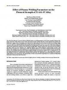
FIGURE 2. The growth rate of looning modes at an ITB as tion of dimensionless parameter tifying the sheared toroidal κ = qR/SvA × d/dr(rvT /Rq).
FIGURE 1. The growth rate of the n = 1 internal kink mode as a function of toroidal velocity with flat and linearly sheared rotation profiles. Also shown for comparison is the predicted stabilisation from reference [18].
1.25
1.5
the bala funcκ quanrotation,
Figure 1 shows the growth rate, γ = Re(λ ) of the internal kink mode normalised to unity as a function of the toroidal velocity normalised to the Alfvén speed, which is in good accordance with Equation (9). The growth rate of the mode decreases as the toroidal velocity increases, whether the flow is sheared or constant. As the flow reaches κ = 1 the mode is stabilised. The value of flow required to stabilise the internal kink mode is within 15% of the analytical predictions based on considering the inertial layer only. The n = 1 internal kink mode is stabilised by flows of the order vφ /cs < 0.15, (cs = (Te /mi )1/2 ) for which it has been shown [19] that a static equilibrium is an appropriate approximation. The influence of toroidal flow shear on finite-n ballooning modes is analysed and compared to analytic theory as another benchmark test of MISHKA-F. Ideal MHD predicts that ballooning modes will be unstable in regions of high pressure gradients, for instance, as found at transport barriers established in high confinement mode (Hmode). Ballooning mode stability at an internal transport barrier (ITB) with respect to the sheared toroidal flow was predicted in Reference [20] where it is suggested that the effect of flow shear will become more significant at low magnetic shear. The equilibrium used for this benchmark has a steep localised pressure gradient and is unstable to ballooning modes but stable to Mercier modes. Figure 2 shows the growth rate of the ballooning modes as a function of the parameter κ representing the sheared toroidal flow. In accordance with Equation (9) the growth rate reaches zero when κ ≈ 1. Here the magnetic shear and the flow shear are evaluated at the radial position at which the ballooning mode is most unstable. As the sheared toroidal rotation is increased, the ballooning mode eigenfunction narrows in radial extent, consistent with the predictions made in Reference [20]. This narrowing of the mode structure continues to the point when κ is sufficiently high to stabilise the mode, at which point the eigenfunction disappears. In this case, the low magnetic shear means that κ ∼ 1 can be reached by low toroidal flows, vφ /cs < 0.1, which satisfies the criterion for using a static equilibrium.
42
Downloaded 24 Aug 2011 to 194.81.223.66. Redistribution subject to AIP license or copyright; see http://proceedings.aip.org/about/rights_permissions
4
0.0
0.34
0.37
0.36
0.35
Sawtooth Period (s)
SXR
13575 (1.56MW Counter)
0.38
SXR
13369 (1.61MW Co)
3
0.0
2
0.0
1
0.0
0
0.36
0.37
Time (s)
0.38
-150
0.39
FIGURE 3. Soft X-ray emission for two approximately identical MAST discharges with similar beam power injected in opposite directions with respect to I p .
-100
0 -50 Toroidal Velocity (km/s)
50
100
FIGURE 4. Sawtooth period for MAST discharges with respect to the toroidal rotation speed at the q = 1 surface.
3. SAWTEETH EXPERIMENTAL RESULTS FROM MAST Sawtooth behaviour is compared in MAST plasmas with approximately matching flattop currents, magnetic fields and plasma shapes. The experimental results presented here expand the range of rotation speeds over which sawtooth behaviour has been considered since flows in MAST are significantly higher than in the previous JET results [14]. Figure 3 shows the soft X-ray traces from two shots in MAST with similar injected beam power but oriented in opposite directions with respect to the plasma current. At the time of the first sawtooth crash, in shot 13575, I p = 719kA, BT = 0.36T and n¯ e = 2.24 × 10²⁰ m−3 whilst in discharge 13369, I p = 723kA, BT = 0.4T and n¯ e = 2.26 × 10²⁰ m−3 . The NBI directed in the co-current direction (discharge 13369) results in a quiescent time which is over twice as long as that when the NB is injected in the counter-current direction. Figure 4 shows the sawtooth period with respect to the rotation speed at the q = 1 surface for plasmas which have the following parameter ranges: I p ∈ [680, 740]kA, BT ∈ [0.35, 0.45]T and ne ∈ [1.6, 2.2] × 1020 m−3 . Here we use the convention that negative rotation velocity is in the counter-I p direction whereas positive rotation is in the co-I p direction. The plasma toroidal velocity is found by using charge exchange measurements of carbon ions. The sawtooth inversion radius is found from the soft Xray signals and this is used to estimate the radial location of the q = 1 resonant surface. As the co-NBI is increased in MAST, the sawtooth period also increases. Conversely, as the counter-NBI is increased, the quiescent time decreases until it reaches a minimum at vφ ∼ 60km/s, and then subsequently lengthens, analogous to the co-NBI regime. The results obtained are consistent with those from JET [14]. The rotation profile is significantly flatter and broader in counter-NBI discharges, where large first-orbit losses are caused by the fact that the injected ions move radially outward from the point of ionisation [21]. A typical counter-injected trapped ion is lost
43
Downloaded 24 Aug 2011 to 194.81.223.66. Redistribution subject to AIP license or copyright; see http://proceedings.aip.org/about/rights_permissions
Precursor Frequency (kHz)
40 30 20 10 0 -10 -20 -30 -2
-1
0 NBI Power (MW)
1
FIGURE 5. Sawtooth precursor frequency as a function of injected beam power. The convention here is that negative precursor frequency corresponds to the mode rotating in the counter-I p direction and positive frequency means that mode rotates in the co-I p direction. The frequency changes direction when the plasma rotation and ion diamagnetic rotation are balanced by the momentum input from the injected neutral beams.
on the outboard leg of its banana orbit, when it is moving in the co-current direction. This means that counter-NBI can result in larger rotation speeds [21], since the angular momentum transferred to the plasma through the J × B torque is larger than during co-injection. Koslowski proposed that the sawtooth period has a minimum when the MHD rotation in the tokamak frame is stopped [15]. This occurs when the rotation resulting from the beam momentum input balances the sum of the toroidal components of the E × B rotation and the ion diamagnetic drift. The sawtooth crash is preceded by a growing oscillation known as the sawtooth precursor. In Ohmically heated discharges in MAST, the precursor mode rotates in the same direction as the plasma current. As such, momentum input in the counter-current direction is required to balance the MHD rotation, at which point the sawtooth period is minimised. Figure 5 shows the frequency of the sawtooth precursor with respect to the injected neutral beam power. Here we use the convention that negative precursor frequency indicates that the mode is rotating in the opposite direction to the plasma current. This means that the precursor mode changes direction of rotation when PNBI ≥ 0.6MW is injected in the counter-current direction. It is at the point when the frequency changes sign that the MHD rotation is balanced by the rotation arising from the momentum input of the beams. Whilst the inhomogeneous nature of the experimental data with respect to beam power does not allow an exact determination of the transition, it does show that it occurs when the beam is oriented in the counter-current direction, consistent with Koslowski’s hypothesis.
4. MODELLING THE STABILISATION OF THE n = 1 INTERNAL KINK MODE BY TOROIDAL ROTATION The stability of the ideal n = 1 internal kink mode with respect to the toroidal rotation at finite ion diamagnetic frequency has been analysed using the MISHKA-F code.
44
Downloaded 24 Aug 2011 to 194.81.223.66. Redistribution subject to AIP license or copyright; see http://proceedings.aip.org/about/rights_permissions
0.05
Co-Rotation Profile Counter-Rotation Profile
0.04 Growth Rate
Growth Rate
0.04
0.05
τ=0 τ=0.001 τ=0.002
0.03
0.03
0.02
0.02
0.01
0.01 0 -200
0 -200
-100 0 100 Core Toroidal Rotation Velocity (km/s)
-100 0 100 -150 -50 50 Core Toroidal Rotation Velocity (km/s)
150
FIGURE 7. The growth rate of the ideal n = 1 internal kink mode in discharge 13035 with respect to the core toroidal rotation using different experimental rotation profiles (circles = co-NBI, squares = counter-NBI).
FIGURE 6. The growth rate of the ideal n = 1 internal kink mode in discharge 13541 as a function of the toroidal rotation speed. The parameter τ represents the ion diamagnetic frequency.
In order to quantify the importance of the rotation profile, we employ a simple model equilibrium with a pressure profile, dp/dψ = p� = p� (0)(1 − ψˆ ) and a current profile, j� = j(0)(1 − ψˆ ) where ψˆ is normalised poloidal flux. The plasma has a circular boundary, an aspect ratio of 10, safety factor on-axis, q 0 = 0.8 and poloidal beta, β p = 0.3. The equilibrium is static and unstable to the ideal n = 1 internal kink mode. The stability of this equilibrium to the internal kink mode is tested with respect to a constant toroidal rotation profile and a linearly sheared (with respect to ψ ) profile which has the same magnitude of rotation at the q = 1 surface. The results show that the stability boundary is identical for the two different rotation profiles and clearly indicates that the toroidal rotation at the q = 1 surface governs the stability of the n = 1 internal kink mode with respect to toroidal flows. The importance of the radial location of q = 1 means that it is imperative to reconstruct the equilibrium with an accurate q-profile. In MAST the standard equilibrium reconstruction is performed using EFIT [22] with just external magnetic data. The equilibrium produced by EFIT can subsequently be improved by using the pressure profile derived from the Thompson Scattering diagnostic, which gives profiles for the electron density and temperature. Using both the inboard and outboard Thompson Scattering data allows isothermal surfaces to be constructed along the length of the major radius and so indicates the relative radial location of the flux surfaces. Finally, the soft X-ray diagnostic can be used to find the inversion radius of the sawtooth oscillations, and hence ascertain the location of the q = 1 surface. The drawback with this process is that the q-profile is not measured directly in MAST and so the soft X-ray calculation of the inversion radius to set q = 1 is the only information about the q-profile in the core. The sensitivity of n = 1 stability with respect to changes in the q-profile has been investigated theoretically by changing the current profile in the core whilst keeping the q = 1 surface in the same position. The stability boundary of these equilibria with respect to sheared
45
Downloaded 24 Aug 2011 to 194.81.223.66. Redistribution subject to AIP license or copyright; see http://proceedings.aip.org/about/rights_permissions
flow was only nominally affected by changes to the q-profile in the core, and hence the location of the q = 1 surface is the key factor in accurate equilibrium reconstruction. When q0 is raised but the shape of the monotonic q-profile is unaltered, hence reducing rq=1 , the stability boundary is changed. In order to analyse the experimental results illustrated in Section 3, MISHKA-F has been used to test the stability of two MAST equilibria with respect to toroidal flows of the order of magnitude observed experimentally. The discharges concerned are 13035 (a discharge with co-injected neutral beam power of 1.82MW, I p = 730kA, BT = 0.408T, n¯ e = 1.6×10²⁰ m−3 and maximum rotation speed, vφ ≈ 230km/s) and 13541 (a shot with counter-NBI of 1.92MW, I p = 730kA, BT = 0.407T, n¯ e = 1.9 × 10²⁰ m−3 and a peak toroidal rotation speed, vφ ≈ 170km/s). The pressure and current profiles together with the plasma shape from EFIT are supplied as input for the HELENA [23] code, which generates the equilibria used by MISHKA-F. HELENA solves the static Grad-Shafranov equation and so the effect of toroidal rotation is not included in the equilibrium. This assumption is valid for subsonic toroidal rotation, when Mt ≤ 0.2, as shown by the CASTOR-FLOW code which can perform stability analyses with stationary equilibria including toroidal flows [19]. The experimental rotation profiles used in the stability analyses are represented by quartic polynomials as: vφ13035 = v13035 [0.6406 + 1.6425s + 0.564s2 − 9.5009s3 + 6.6498s4] 0
(10)
vφ13541 = v13541 [0.7392 − 0.3397s + 5.6457s2 − 9.9688s3 + 4.071s4 ] 0
(11)
The growth rate of the kink mode decreases as the toroidal rotation is increased in the co-current direction. However, when there is a finite ion diamagnetic frequency, the n = 1 internal kink mode is initially destabilised by toroidal rotation in the counter-ω ∗i direction, before being completely stabilised at high toroidal flows. This is consistent with the results found experimentally in MAST. Figure 6 shows the growth rate of the n = 1 internal kink mode in discharge 13541 with respect to the rotation velocity at the magnetic axis. The toroidal rotation has a profile given by Equation 11. As the ion diamagnetic frequency is increased, the toroidal rotation velocity at which the n = 1 internal kink mode is most unstable increases in the counter-ω∗i direction. Using experimental values for the ion diamagnetic frequency and the rotation profile, the core toroidal rotation required to stabilise the n = 1 kink mode is nearly twice as high in the counter-ω∗i direction as in the co-ω∗i direction. Figure 7 shows the growth rate of the mode in discharge 13035 with respect to the core toroidal rotation velocity for the rotation profiles as given in Equations 10 and 11. In this instance the co-ω ∗i rotation profile exhibits stronger stabilisation of the n = 1 kink mode because the q = 1 surface is localised to the plasma core at s ≈ 0.3, where the rotation is larger in Equation 10 than Equation 11. The filled symbols in Figure 7 represent a “real” rotation profile (that is to say, using the profile of 13541 in the counter-I p direction and that of 13035 in the co-I p direction). The sawtooth period is an inherently non-linear property, so in order to use linear stability analysis to address this we use the experimental observation that the q = 1 surface increases radially as a function of time[24] between sawtooth crashes, r q=1 ∼ τST . As q0 is increased towards 1, the position of the q = 1 surface moves radially
46
Downloaded 24 Aug 2011 to 194.81.223.66. Redistribution subject to AIP license or copyright; see http://proceedings.aip.org/about/rights_permissions
inwards, since the q-profile is monotonically increasing. The marginally stable q = 1 position with respect to the toroidal rotation speed at the q = 1 surface is plotted in Figure 8. The scans represented in this figure are for the n = 1 internal kink mode in co-NBI discharge 13035 using the experimental rotation profile and ion diamagnetic frequency. The marginal q = 1 surface is nearest to the centre at approximately the same counter-vφ as required to minimise the sawtooth period. Using the assumption that rq=1 ∼ τST this suggests good accordance between the MISHKA-F stability analyses and the experimental data from MAST. We also assume that the kinetic stabilisation due to the fast ions injected by the neutral beam does not vary with r q=1 and is dominated here by the fluid effects. Both the MAST experimental results presented in Section 3 and the results from modelling with MISHKA-F show good agreement with References [8, 9]. Waelbroeck [8] proposed that increasing vφ would result in strong gyroscopic stabilisation of the ideal n = 1 internal kink mode. Wahlberg and Bondeson [9] also showed that the centrifugal forces resulting from the toroidal rotation would lead to the stabilisation of the internal kink mode for rotational frequencies of the order Ω/ωA ∼ ε , where ε is the inverse aspect ratio and ωA = svA /qR is the Alfvén frequency. MISHKA-F modelling shows that rotation below half of the ion sound speed (which is 680 km/s in discharge 13541) can stabilise the n = 1 kink mode, just as theory predicted. However, whilst the centrifugal force established by the toroidal rotation explains why the n = 1 kink mode is stabilised at high toroidal flows, it does not explain the asymmetry between co- and counter-NBI. Analytically, the growth rate of the internal kink mode as a function of the toroidal velocity can be found by using Equation 7. In these studies, the κ terms will be small since the toroidal velocity shear is much smaller than the Alfvén frequency and the magnetic shear is not very low. In the limit vφ vA and s ∼ 1, Equation 7 becomes Ω ≡ ω − Ωφ � ω∗i
(12)
This means that the precursor mode frequency will change direction when Ω φ � −ω∗i , which is to say that the toroidal rotation frequency of the plasma induced by the NBI balances the ion diamagnetic frequency. This is consistent with experiment as the diamagnetic drift has a toroidal component, which adds to the toroidal flow when the beam is injected co-current and so stabilises the internal kink mode more readily. When the beam is injected in the counter-current direction, the flow due to the beam first has to overcome the toroidal component of the diamagnetic drift before it can stabilise the kink mode. In fact, when the beam induced flow is low it simply reduces the stabilising diamagnetic flows, and hence drives the kink instability. The flow-dependent term in Equation 7 has no dependence upon the direction of the flow. The asymmetry in the fluid picture arises from the direction of the ion diamagnetic drift. Such fluid effects are applicable in MAST due to the high toroidal rotation achievable. However, the experimental results from JET [14] cannot be explained by fluid effects since the flows are an order of magnitude smaller than in MAST. Graves et al [10] presented a kinetic treatment of the stabilising effects of neutral beam injected ions on sawteeth.
47
Downloaded 24 Aug 2011 to 194.81.223.66. Redistribution subject to AIP license or copyright; see http://proceedings.aip.org/about/rights_permissions
0.05 n= 3 n= 6 n=10 n=15
0.04
0.5
0.3
0.02
0.2 0.01
A
0.4
γ/ω
0.03
Sawtooth Period (s)
Normalised Radial Location of q=1
0.04
-100 0 100 Toroidal Rotation Velocity at q=1 Surface (km/s)
0.02 0.01
0.1 0 -200
0.03
0 0
0
FIGURE 8. The radial location of the marginally stable q = 1 surface in discharge 13541 with respect to the toroidal rotation at the resonant surface (squares). Also shown for comparison is the sawtooth period of shots in MAST (open circles).
20 40 Vped.top [km/s]
60
FIGURE 9. The growth rate of the n = 3, 6, 10, 15 modes normalised to Alfvén speed with respect to the toroidal velocity at the top of the pedestal. The equilibrium is from MAST shot 8209.
5. MODELLING THE EFFECT OF TOROIDAL ROTATION ON EDGE PEELING-BALLOONING MODES The beam-induced toroidal rotation in an H-mode MAST plasma has a very steep radial gradient near the plasma edge. This sheared rotation can have a stabilising effect on the peeling-ballooning modes thought to act as a trigger for ELMs. We study this effect by reconstructing a MAST equilibrium (discharge 8209) which is ideally unstable to peeling-ballooning modes and investigating its stability with respect to sheared edge rotation using the ELITE code [25]. As before, we employ a static equilibrium which is only valid for vφ cs . The sheared region has a width of 2% of the poloidal flux and is centered at the maximum pressure gradient (ψˆ = 0.991). The width corresponds to approximately 1 cm in minor radius which represents the best estimate for the experimental velocity pedestal width in MAST H-mode. The experimental toroidal velocity is about 25 km/s at the top of the pedestal (∼ 0.15cs) and falls to zero at the separatrix [26]. The growth rates of the peeling-ballooning modes with respect to the toroidal rotation at the top of the edge pedestal are shown in Figure 9. Here we assume a fixed rotation profile and only vary the magnitude of rotation at the top of the pedestal. The modes with high-n are stabilised by the rotation more easily than those with low-n, as expected [27]. The velocity at which significant stabilisation of the modes occurs is in the range of the experimental value of the pedestal top toroidal velocity. During an ELM, the velocity profile flattens [26]. The disappearing velocity shear during an ELM and the stabilising effect of the velocity shear on the peeling-ballooning modes suggests an ELM-model that is depicted in Figure 10. Prior to an ELM (1), the edge plasma is unstable to low- to intermediate-n modes in the absence of rotation shear.
48
Downloaded 24 Aug 2011 to 194.81.223.66. Redistribution subject to AIP license or copyright; see http://proceedings.aip.org/about/rights_permissions
Velocity
Velocity
Velocity
Velocity
Pressure Stability limit, dv/dr=0 Stability limit, dv/dr≠ 0 0.9
1
0.92
0.94
0.96
Pressure Stability limit, dv/dr=0 Stability limit, dv/dr≠ 0
0.98
1 0.9
0.92
0.94
0.96
Pressure Stability limit, dv/dr=0 Stability limit, dv/dr≠ 0
Pressure Stability limit, dv/dr=0 Stability limit, dv/dr≠ 0 0.98
1 0.9
2
0.92
0.94
0.96
3
0.98
1 0.9
0.92
0.94
0.96
0.98
1
4
FIGURE 10. A schematic diagram of the edge velocity profile, plasma pressure, stability limits and edge flux surfaces during the evolution of an ELM.
However, a strong rotation shear is able to stabilise these modes until the pressure gradient becomes sufficiently steep to exceed the stability limit and drive the peelingballooning modes. Then an unstable mode starts to grow (2). As it grows, it ties together adjacent flux surfaces and subsequently flattens the velocity profile (3). As the stabilising effect of the flow shear is reduced, the mode grows even faster and leads to an ELM that then relaxes the pressure profile below the stability limit(4). In addition to the transport due to the MHD instability, the loss of flow shear could lead to a loss of the edge transport barrier, further increasing the transport in the edge region. After the ELM crash, the pressure profile has relaxed below the stability limit and the cycle starts again. This ELM-triggering model is only applicable in spherical tokamaks with high edge rotation velocities. The stabilising effect of the rotation shear becomes weaker as the aspect ratio increases. The rotation shear has only a nominal effect on the stability of peeling-ballooning modes in conventional tokamaks, and so the standard ELM model [28] applies in large aspect-ratio machines.
6. CONCLUSIONS MHD stability analyses including toroidal rotation effects have accurately modelled sawtooth behaviour on MAST and led to the prediction of an ELM trigger model for spherical tokamaks. The MAST geometry and beam power per plasma volume means that toroidal flows can approach the ion sound speed and lead to rotation effects which are not applicable in conventional tokamaks. Results from MAST show that the sawtooth period increases when the toroidal flow increases in the co-current direction. Conversely when the flow increases in the countercurrent direction, the sawtooth period reaches a minimum dependent upon the ion diamagnetic drift. Modelling with MISHKA-F shows excellent agreement with the experimental results obtained from MAST. It has been shown that the radial location of the q = 1 surface for marginal stability increases with co-current rotation, but decreases to some minimum in the counter-current regime. The toroidal velocity at which the q = 1 radius for marginal stability is minimised agrees well with that at which the experimental sawtooth period is at a minimum. It is also found that the ideal n = 1 internal kink mode
49
Downloaded 24 Aug 2011 to 194.81.223.66. Redistribution subject to AIP license or copyright; see http://proceedings.aip.org/about/rights_permissions
stabilisation by flow is determined by the magnitude of the flow at the q = 1 rational surface, rather than the flow shear. The sheared toroidal rotation at the plasma edge has been shown to have a stabilising effect on the peeling-ballooning modes thought to be the trigger for ELMs. The stabilising effect is stronger for higher-n modes. The following model for ELM triggering in spherical tokamaks has been proposed: Initially the peeling-ballooning modes are stabilised by the flow shear. As the pressure gradient increases, the destabilising force becomes larger than the flow shear stabilisation and drives the modes. As the mode grows, it ties adjacent flux surfaces together and flattens the rotation profile, exacerbating the instability and leading to the ELM crash.
ACKNOWLEDGMENTS This work was partly funded by the United Kingdom Engineering and Physical Sciences Research Council and by the European Communities under the contract of Association between EURATOM and UKAEA. The views and opinions expressed herein do not necessarily reflect those of the European Commission.
REFERENCES 1. 2. 3. 4. 5. 6. 7. 8. 9. 10. 11. 12. 13. 14. 15. 16. 17. 18. 19. 20. 21. 22. 23. 24. 25. 26. 27. 28.
Y. Liu, A. Bondeson, Y. Gribov, and A. Polevoi, Nucl. Fusion 44, 232 (2004). I. Chapman, S. Sharapov, G. Huysmans, and A. Mikhailovskii, Phys. Plasmas 13, 065211 (2006). I. Chapman, et al., The effect of toroidal plasma rotation on sawteeth in MAST (2006), sub Nucl. Fusion. S. Saarelma, et al., MHD stability analysis of ELMs in MAST (2006), sub Plasma Phys. Control. Fusion. C. Gimblett, Nucl. Fusion 26, 617 (1986). J. Connor, R. Hastie, and J. Taylor, Plasma Phys. Control. Fusion 46, B1 (2004). M. Furakawa, and S. Tokuda, Nucl. Fusion 45, 377 (2005). F. Waelbroeck, Phys. Plasmas 3, 1047 (1996). C. Wahlberg, and A. Bondeson, Phys. Plasmas 7, 923 (2000). J. Graves, O. Sauter, and N. Gorelenkov, Phys. Plasmas 10, 1034 (2003). N. Oyama, Y. Sakamoto, A. Isayama, et al., Nucl. Fusion 45, 871 (2005). K. Burrell, M. Austin, D. Brennan, et al., Plasma Phys. Control. Fusion 44, A253 (2002). C. Angioni, et al., Plasma Phys. Control. Fusion 44, 205 (2002). M. Nave, et al., 31st EPS Conference Plasma Phys. Control. Fusion 28G, P1.162 (2004). H. Koslowski, Fusion Sci. Technology 47, 260 (2005). J. Menard, et al., Nucl. Fusion 43, 330 (2003). A. Mikhailovskii, G. Huysmans, S. Sharapov, and W. Kerner, Plasma Phys. Rep. 23, 844 (1997). A. Mikhailovskii, and S. Sharapov, Plasma Phys. Control. Fusion 42, 57 (2000). E. Strumberger, et al., Nucl. Fusion 45, 1156 (2005). A. Webster, H. Wilson, and A. Scaife, Phys. Plasmas 11, 2135 (2004). P. Helander, R. Akers, and L. Eriksson, Phys. Plasmas 12, 112503 (2005). L. Appel, M. Bevir, and M. Walsh, Nucl. Fusion 41, 169 (2001). G. Huysmans, A. Mikhailovski, S. Sharpov, and W. Kerner, Phys. Plasmas 8, 4292 (2001). V. Udintsev, et al., Plasma Phys. Control. Fusion 47, 1111 (2005). H. Wilson, P. Snyder, G. Huysmans, and R. Miller, Phys. Plasmas 9, 1277 (2002). A. Kirk, et al., Plasma Phys. Control. Fusion 47, 315 (2005). A. Webster, and H. Wilson, Phys. Rev. Lett. 92, 165004 (2004). J. Connor, R. Hastie, H. Wilson, and R. Miller, Phys. Plasmas 5, 2687 (1998).
50
Downloaded 24 Aug 2011 to 194.81.223.66. Redistribution subject to AIP license or copyright; see http://proceedings.aip.org/about/rights_permissions