macros that replace standard PVM routines with calls to PVaniM's monitoring library. In many cases the ... average number of jobs in the run queue of the host. A novel ..... GIT-CC-94-21, Georgia Institute of Technology, Atlanta, GA, 1994. 4] Heath ... 5] Kohl, J. A. and Geist, G. A. The PVM 3.4 tracing facility and XPVM 1.1.
Monitoring and Visualization in Cluster Environments Brad Topol� John T. Stasko� Vaidy Sunderamy March 1996
GIT-CC-96-10
Abstract Cluster computing has evolved into a popular and e�ective mode of high performance computing. Cluster environments are intrinsically di�erent from hardware multiprocessors, and hence require a di�erent approach to measuring and characterizing performance, monitoring an application's progress, and understanding program behavior. In this article, we present the design and implementation of PVaniM, an experimental visualization environment we have developed for the PVM network computing system. PVaniM supports a two-phase approach whereby on-line visualization focuses on large-grained events that are in uenced by and relate to the dynamic cluster environment, and postmortem visualization provides for detailed program analysis and tuning. PVaniM's capabilities are illustrated via its use on several applications and it is compared with other visualization environments developed for cluster computing. Our experiences indicate that for several classes of applications, the two-phase visualization scheme can provide more insight into the behavior, e�ciency, and operation of distributed and parallel programs in cluster environments. � y
Author's address: College of Computing, Georgia Institute of Technology, Atlanta, Georgia 30332-0280. Author's address: Department of Math and Computer Science, Emory University, Atlanta, GA, 30322
1
1 Introduction Cluster computing, or distributed and parallel processing on networked collections of computer systems, has evolved into a popular and e�ective mode of high-performance computing. Numerous advantages, including ready availability, low cost, incremental scalability, and robust programming models and environments have brought clusters into the mainstream, for both scienti c and general purpose applications. Moreover, the same programming models and methodologies can be used across a wide variety of platforms, ranging from true clusters (e.g. stacks of headless workstations with high speed interconnects) to collections of desktop systems to geographically distributed hierarchies of machines of multiple architecture types. Each type of platform has unique advantages, in addition to the common bene ts of utilizing a collection of networked computer systems as a coherent concurrent computing resource. Network and cluster computing1 , however, is not without its share of obstacles. Typically, applications execute on workstations that have varying capabilities and con gurations in terms of CPU speed, memory, local vs. networked disks, etc. Furthermore, in open cluster environments, each computer as well as the network itself, is potentially subject to uncontrollable external loads. These factors often result in load imbalances and dynamic uctuations in delivered resources, which can be a major cause of performance degradation[8]. Cluster environments are therefore intrinsically di�erent from most hardware multiprocessors where typical operational methodology is for applications to have dedicated use of the machines or parts thereof. Therefore, in clusters, measuring and characterizing performance, as well as monitoring application progress and understanding program behavior, requires a di�erent approach from traditional methods suitable for monolithic parallel processors. Graphical visualization can provide insight into application operation, behavior, and performance. Particularly in cluster and network environments, visualization can help understand the many complex and variable factors that exist. As in other environments, In this paper, we focus on collections of general purpose workstations on standard networks, e.g. Ethernet, and hence use the terms \network computing" and \cluster computing" interchangeably 1
2
visualization can be enabled by observing execution events and displaying them in graphical form. However, given the nature of clusters, these events can and should be divided into two categories and analyzed from di�erent perspectives { large grained events in uenced by and relating to the (dynamic) environment, and detailed collections of events describing the execution path of the parallel program in question. While subsets of these two categories are certainly related and possibly even the same, their use is for fundamentally di�erent purposes. In this paper, we adopt the position that monitoring and visualization in cluster environments should follow a two-phase approach, with run time or on-line monitoring focusing on visualization and interaction during execution, and postmortem monitoring or pro ling being used for detailed program analysis and tuning.
In order to investigate this two-phase approach to visualization in networked environments, we have developed an experimental toolkit and methodology called the PVaniM visualization environment. PVaniM is a visualization environment for the PVM[10] network computing system which relies on its own monitoring techniques to support its graphical views. The following are the primary novel features of the PVaniM system: �
Graphical views tailored to cluster environments{Developing visualization support for clusters is more involved than simply porting traditional multicomputer tools such as ParaGraph[4] to the environment. Typically, these tools do not provide views that illustrate external loads on the processing elements. Furthermore, they were originally meant for multicomputers which did not support multitasking[1]. In contrast, cluster environments are composed of multitasking workstations and multiple tasks may be assigned to each host. The PVaniM system provides monitoring and visualization support that encompasses both of these crucial aspects of cluster environments.
�
Separation of on-line and postmortem visualization functionality{Many visualization environments use the same graphical views (and hence the same monitoring techniques) to support both their on-line and postmortem visualizations. For example, Hence[1], Xab[1], and XPVM[5] all utilize event tracing which permits very detailed graphical views. While these types of views are very appropriate for o�-line analysis, they require a large amount of network bandwidth when used on-line. In contrast, PVaniM distinguishes between the types of monitoring and graphical views used for on-line analysis and those used for detailed postmortem analysis. For o�-line analysis, PVaniM uses bu�ered postmortem tracing[11], using a bu�ering hierarchy for collecting trace events. For on-line graphical views, PVaniM utilizes periodic sampling of tasks with adjustable granularity; this requires substantially less bandwidth than event trac-
3
ing but the views are not as detailed. The result is a system which provides graphical views with a wide range of level of detail while minimizing the network bandwidth required for monitoring. The on-line graphical views of PVaniM are resilient enough to support long running and communication-intensive PVM applications. �
Support for interactive steering{Recent work on shared memory parallel processors has shown interactive steering to be extremely useful for large-scale molecular dynamics applications[3]. Steering essentially involves allowing a user to inspect and modify a program's attributes while it is executing. In order to integrate steering functionality into a cluster environment, an enhancement layer is necessary that allows external messages to be sent from an external task to application tasks. The messages contain encoded steering information. PVaniM transparently integrates this support. That is, steering is integrated such that no external library calls need to be embedded in the code nor are extra sockets necessary for the reception of steering messages. Transparently integrating this support is complex as the steering layer must guarantee that steering messages are not mistaken by the application as normal communication.
�
User controllable monitoring overhead{One example use for PVaniM interactive steering support is allowing the user to interactively control the periodic sampling rate of the on-line monitoring. A slider is provided that allows the user to increase or decrease the rate at which on-line monitoring data is sent to the graphical views. With lower sampling rates, the application will experience less perturbation, but the graphical views will not be updated as frequently. This allows users to try di�erent sampling rates and nd one that is most suitable to their personal tastes and the needs of their application.
�
Transparent I/O support{PVaniM provides routines similar to scanf() and printf() that allow for rudimentary input/output with the executing application. When the graphical monitor is used, the output routines are directed to the monitor. When the monitor is not in use, these routines default to standard printf() and scanf() if the PVM task is connected to a terminal. This allows for many network computing applications to transparently prompt correctly for application parameters whether or not PVaniM's graphical monitor is being utilized.
This paper provides an extensive overview of the PVaniM system and its contributions to cluster computing visualization and interactive steering. In Section 2 a detailed description of PVaniM is provided. Section 3 illustrates the system's usefulness with several applications including those using load balancing strategies recommended for cluster environments. Section 4 provides system implementation details of PVaniM's functionalities. Section 5 discusses related work. The nal section presents conclusions and future work. 4
2 PVaniM The PVaniM system provides both on-line and postmortem visualizations of applications written with the PVM[10] heterogeneous network computing system. After making minor modi cations to the application and recompiling to link to PVaniM's monitoring library, PVaniM is ready for use. Essentially, the user must add an extra header le which provides macros that replace standard PVM routines with calls to PVaniM's monitoring library. In many cases the PVaniM macros eventually call the intended PVM routine. However, some of PVM's more advanced primitives could not be supported in this manner because of PVaniM's goal to support a transparent steering framework. These routines are reimplemented by PVaniM to allow transparent steering. The complexities and implementation issues associated with this are discussed in a following section. Although minor modi cations are necessary for an application to be \PVaniM aware", these modi cations do not have to be repeatedly added or removed. They perform correctly whether or not the PVaniM's monitoring and graphical views are being used. The use of PVaniM to spawn the application determines whether or not monitoring and visualization are utilized. The following subsections describe PVaniM's on-line and postmortem monitoring and visualization capabilities.
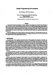
2.1 PVaniM On-Line Visualization Support Figure 1 presents a typical PVaniM program view. At the upper left is a Host List view, identifying the host machines used by the application and the placement of tasks (integer IDs) on each of these hosts. To the right of the Host List view is the Load Information view. This view provides insight into the aggregate load on the host machines by providing a graphical view of the average number of jobs in the run queue of the host. A novel feature of this view is its ability to account for external loads as well as PVM task loads. Next to the Load Information view is the Host Utilization view, where each host is 5
Figure 1: Snapshot of PVaniM runtime graphical views.
6
characterized by a green-yellow-red rectangle. Green is used to represent the percentage of time the host spends computing, yellow represents the percentage of time performing PVM message sends, and red represents the percentage of time the host is idle waiting to receive PVM messages. For each host, utilization is a composition of the statistics of all the PVM tasks running on that host. This information is also presented on a per-task basis in the Task Summary view.
Adjacent to the Host Utilization view is the Memory Use view, illustrating the aggregate amount of memory utilized by the PVM tasks on each host. By clicking the pointer on rectangles in the Memory Use view, more detailed textual usage statistics are displayed in PVaniM's output box in the lower left. Below the Task Summary view is the MESSAGES SENT/bytes sent view. Clicking the pointer on the view label toggles whether a message count or a bytes total is shown. This view presents interval rather than aggregate statistics. That is, the view illustrates how much message tra�c has occurred by a task since the last time it reported statistics to the monitor. The TOTAL MATRIX COMM/interval matrix comm view provides both aggregate and interval statistics regarding message communication between tasks (sender in row, receiver in column). In its default form, the view provides aggregate statistics and the message key scales automatically as the number of messages increases. By selecting the view label, one can change the view to provide this information on an interval basis as discussed with the prior view. In the interval mode, the user is allowed to interactively change the range values of the message legend to nd a range most appropriate for the phase of the application.
2.1.1 Achieving Views Tailored to Cluster Environments PVaniM's graphical views are tailored to executing in a cluster environment. PVaniM provides a load information view which presents external load information in addition to load incurred by PVM tasks. Providing this information is of great value because varied external loads are extremely prevalent in cluster environments. 7
Another common aspect of cluster environments is that workstations have various amounts of memory. With PVaniM's Memory Use view, the user is well aware of the amount of memory utilized by PVM tasks. Should a task begin to consume a large amount of memory on a workstation with minimal memory, this situation is identi able and hence recti able. Also prevalent in cluster computing is the use of multitasking workstations. Typically, this results in several PVM task executing on each host. PVaniM's graphical views aggregate statistical data to provide graphical views on a per workstation basis in addition to per task graphical views. For example, Figure 1 illustrates several PVM tasks executing on each host. In the Host List view all tasks are listed with the host on which they are executing. Furthermore, the Host Utilization and Memory Use views illustrate how the multiple PVM tasks utilize each workstation as well consume the memory resources of that workstation. In contrast, an equivalent ParaGraph view of this scenario would assume each PVM task was provided its own dedicated processor. Because of this lack of multitasking information, the ParaGraph view would be somewhat misleading.
2.2 Input/Output Views The PVaniM system provides routines similar to
scanf()
and
printf()
that allow for
rudimentary input/output with the executing application. When the graphical monitor is used, the output routines are directed to the PVaniM output box shown in the lower left of Figure 1 and input is mapped to the PVaniM input box which is shown adjacent to the output box. When the monitor is not in use, these routines default to standard printf() and scanf() if the PVM task is connected to a terminal. This allows for many programs to prompt correctly for application parameters whether or not the graphical monitor is being utilized.
2.2.1 Achieving Transparent I/O These views allow PVaniM to provide transparent I/O support for PVM tasks no matter where their location. In addition to supporting primitive debugging, this support is partic8
ularly apropos for PVM process migration systems such as CoCheck[9]. Under CoCheck, a migrated PVM task that is initially connected to a tty loses this connection after the task has migrated. This limits CoCheck's support for interactive applications. However, an application using PVaniM's transparent I/O support simply uses PVM messages to provide I/O. In this situation, interaction support would still be available.
2.3 Steering the Sampling Rate Towards the bottom of Figure 1 is a slider widget with a numerical eld above it. This slider allows the user to interactively \steer" the sampling rate of PVaniM. PVaniM utilizes periodic sampling instead of tracing to \drive" its on-line graphical views in order to minimize monitoring bandwidth requirements. With a higher sampling rate the graphical views are updated much more frequently with the result that more network bandwidth is utilized for monitoring and the application will experience more perturbation.
2.3.1 Achieving User Controllable Monitoring By allowing the user to interactively control the rate at which the views are updated, PVaniM allows the user to control the monitoring overheads incurred by the application. The user has the exibility of choosing a sampling rate and nd a value that is most suitable for the application. Applications which have a tendency to deadlock may utilize higher sampling rates to allow for frequent examination by the user. In contrast, more stable applications can utilize lower sampling rates and further minimize the monitoring overhead.
2.3.2 Achieving Interactive Steering PVaniM's support for steering the sampling rate is general enough to provide support for the steering of objects as well. Essentially, an interaction handler is provided which can pass steering data to more abstract steerable object primitives while guaranteeing this data is not mistakenly delivered as an application message. As discussed later in this paper, 9
e�orts are underway to support advanced steerable objects originally developed for shared memory parallel processors[12].
2.4 PVaniM Postmortem Visualization Support For postmortem visualization, PVaniM supports event tracing with a technique we refer to as bu�ered postmortem tracing[11]. With this technique, each workstation writes its trace events to its local disk (if available). After the application has nished executing, the individual trace les are collected automatically by PVaniM. This allows PVaniM to perform event tracing without severely impacting the network bandwidth available to the application. The consolidated trace le undergoes rigorous postprocessing to synchronize clocks and add a logical timestamp. The trace le is then used to \drive" PVaniM's detailed, ne-grain pro ling views. Figure 2 is a message passing view from PVaniM's postmortem graphical view library. In this view, all are tasks positioned around the outside circle. Messages are represented as circles that smoothly move into the center of the circle in neighborhood of the task who the message is intended to be received by. Circle size and color are used to represent message size and type, respectively. The messages also may be interactively queried by users to determine the exact size of the message, its type, etc. Furthermore, contrail lines are provided that allow the identity of the sender of the message to be easily determined. Lamport timestamps are utilized to provide a feasible concurrent ordering of events and this ordering is utilized to produce a concurrent animation of message tra�c. As discussed in [11], PVaniM's bu�ered tracing supports its own default library of visualizations and concurrent animations as well as allowing the user to develop applicationspeci c visualizations. Furthermore, PVaniM provides a converter which translates PVaniM trace les to the PICL[2] trace format utilized by ParaGraph[4]. This allows PVaniM to also support ParaGraph views in addition to the visualization capabilities mentioned above. In the remainder of this paper we focus on PVaniM's support for ParaGraph postmortem views to justify PVaniM's separation of on-line and postmortem visualization functionality. 10
Figure 2: Sample view from PVaniM's postmortem view library. PVaniM's own default postmortem graphical views and support for application-speci c postmortem visualizations are thoroughly described in [11].
2.4.1 Achieving Separated On-Line and Postmortem Functionality PVaniM's use of on-line sampling and bu�ered postmortem tracing allows it to achieve functionality at runtime and also used as a postmortem pro ling tool. The avoidance of on-line tracing and on-line graphical views which store substantial state allow PVaniM to support long running, communication-intensive PVM applications. Furthermore, the postmortem trace les support graphical views that allow for detailed (perhaps even tedious) examination of an application's behavior.
11
3 Experiences with PVaniM In this section we present the use of PVaniM on three PVM applications. The rst of these is NAS Parallel Benchmark Kernel MG[13], the second application is a branch and bound application which solves the N-puzzle as described in [7]. The third application is another branch and bound application which solves the traveling salesperson (TSP) problem. Each application utilizes partitioning and load balancing strategies discussed in [8] tailored to network computing environments to varying degrees. In this section we present how PVaniM is utilized as an aid to understanding the complexities of implementing a high performance heterogeneous network computing application. Speci cally, for each application, we provide snapshots of PVaniM's on-line graphical views as well as ParaGraph postmortem views that PVaniM provides via trace le conversion. We then compare PVaniM's view support to XPVM[5]. XPVM also provides on-line and postmortem visualization support but uses the same views in on-line mode as it does it postmortem mode. The version of XPVM used is 1.1, the most recent version of the software available.
3.1 Kernel MG Figure 3 shows NAS Parallel Benchmark Kernel MG executing under PVaniM. In this version, Kernel MG executes four iterations of the V-cycle multigrid algorithm to obtain an approximate solution to the discrete Poisson problem �2 u = v on a 64 x 64 x 64 grid. The implementation assumes a ring topology of communication and both near neighbor and far neighbor communication is present in the application. The algorithm is essentially a direct port of a version developed for the Intel hypercube. As shown in Figure 3, Kernel MG executes on buster and elmyra both SGI R4400 workstations, oakmont, a Sun Sparc 10, and decatur, a Sun Sparc 2 workstation. The Host Utilization view indicates a large amount of red indicating a substantial amount of idle time on the faster workstations buster and elmyra. Essentially, the tasks executing on the faster workstations are not performing enough computation to be fully utilized. This naive implementation, in addition to other factors (e.g. external loads) contribute to the poor performance of this algorithm in the 12
Figure 3: Snapshot of Kernel MG provided by PVaniM's on-line graphical views.
13
cluster environment. Figure 4 shows a snapshot of ParaGraph postmortem views of Kernel MG generated by PVaniM. At the top is the Critical Path view where lines are drawn to indicate message communication between processors and the critical path through the application is shown in red. In the middle is the Utilization Gantt Chart which illustrates processor utilization. Similar to the PVaniM Host Utilization view, green represents computation time, red represents idle time, and yellow represents overhead from performing message sends. At the lower left of Figure 3 is a Communication Matrix view where each square in the two-dimensional array represents message communication between processors. At the bottom right is a Concurrency Pro le view which shows the percentage of time that a certain number of processors are \busy" performing computation. The ParaGraph views provide much greater detail than the on-line views provided by the system, but the ParaGraph views lack external load information and memory utilization views provided by PVaniM's on-line component. Furthermore, because there is a one to one mapping of task to workstation, ParaGraph's utilization information is applicable for this application. Figure 5 shows an XPVM snapshot of the same application. At the top is a Utilization view. This view is an adaptation of ParaGraph's Utilization Gantt Chart but zooming and scrolling capabilities have been added. At the bottom of Figure 5 is a Space-Time view. Again, this is an extension of ParaGraph's Space-Time view that has been augmented with scrolling and zooming support. Although, XPVM also lacks PVaniM's ability to visualize external loads and memory utilization, it is extremely useful for this application for several reasons. First, since there is a one to one mapping of task to workstation, XPVM's utilization information is applicable just as ParaGraph's utilization views were. Second, this is a relatively small application that executes for a short amount of time. Since each task sends no more than 100 messages, and the application executes for about 45 seconds or so, the amount of state information that must be stored by XPVM to perform scrolling and zooming is minimal. XPVM is able 14
Figure 4: ParaGraph postmortem views of Kernel MG provided by PVaniM. to comfortably zoom and scroll with little interaction delay.
3.2 N-Puzzle Figure 6 illustrates an N-puzzle application executing in the PVaniM environment. The N-puzzle problem[7] is a branch and bound application which is solved by searching a state space tree that corresponds to puzzle derivations. A \bag of tasks" approach is utilized in which a master node is responsible for the distribution of puzzle states to the worker tasks. The worker tasks generate the two to four possible con gurations that are directly derived from the received puzzle con guration. They then send these puzzle states back to master node, who reorders them to be resent out to the worker nodes depending upon their feasibility of leading to a solution. The \bag of tasks" approach provides for dynamic load balancing as worker processes acquire more tasks to perform when they complete their current task. The algorithm has 15
Figure 5: XPVM views of Kernel MG.
16
potential to perform well in a cluster environment[8]. The application executes on a combination of SGI R4400 workstations, Sun Sparc 10's, and Sun Sparc 2's. The master node executes on buster, an SGI R4400, and worker nodes execute on the remainder of the workstations. Examination of PVaniM's on-line graphical views yields several interesting observations. First, all of the worker nodes have roughly the same percentage of utilization despite the various capabilities of the workstations and the wide range of external loads. The loadbalancing nature of the application is clearly having an e�ect. Unfortunately, however, the workstations are all being poorly utilized. The large amounts of red in the Host Utilization view indicate this to be so. Second, a large amount of memory is being utilized by the workstation buster. Although this workstation has two tasks executing on it, it is using ten times as much memory as any other workstation. Since node one performs identical operations as nodes two through six and node zero maintains the \bag of tasks", we conclude that the \bag" maintained by node zero is growing quite large. Since this bag is constantly reorganized, it appears likely that this may be a bottleneck in the application. At the very least, it is safe to assume that node zero should always execute on a workstation with a large amount of memory. Figure 7 illustrates ParaGraph postmortem views of N-Puzzle as generated by PVaniM. Here ParaGraph's utilization views are somewhat misleading because there is not a one to one mapping of task to workstation. Two tasks execute on buster, but ParaGraph assumes that each task executes on a dedicated processor. Hence, ParaGraph provides two di�erent processor utilization rectangles for buster in its Utilization Gantt Chart. According to task zero, the utilization rectangle is mostly green and therefore buster is extremely well utilized. According to task one, however, the utilization rectangle is mostly red and buster is appears to be extremely poorly utilized. Clearly, these two rectangle must somehow be compounded together to provide a more accurate representation of buster's utilization. In this application, the user is advised to rely on PVaniM's on-line utilization view because it correctly aggregates the statistics for task zero and task one since they execute 17
on the same workstation as well as doing this for tasks three and four. ParaGraph's other detailed views are still useful, however. For example, after examination with ParaGraph's detailed views, one is able to discern that a large number of small byte messages are prevalent in this application. Essentially, the tasks being distributed to workers are too ne grain and have a very poor communication to computation ratio. Figure 8 shows an XPVM snapshot of the same application. The usefulness of XPVM for this application su�ers for several reasons. First, since XPVM assumes one to one mapping of task to workstation, its utilization view is misleading for the same reason as ParaGraph's utilization views. Speci cally, XPVM also provides two di�erent processor utilization rectangles for buster. Furthermore, although the N-puzzle application only executes for a few minutes, it is communication-intensive. The large amount of communication requires XPVM to store and process a large amount of state to support its zooming and scrolling capabilities. In fact, as seen in Figure 8, the zooming feature became inoperative as we were unable to zoom in and acquire a more detailed view that lled the entire drawing area. Essentially, usability problems occurred due to large interaction delays with the XPVM interface which are a result of XPVM attempting to provide such detailed graphical views on-line. Finally, XPVM does not illustrate task zero's large need for memory nor the external loads present on the workstations.
3.3 TSP An application that solves the traveling salesperson problem e�ectively uses advanced strategies for executing in a network computing environment. In this branch and bound application, a set of partial tours are generated and are searched concurrently. A work queue stores partial tours, and a master node is responsible for distributing partial tours to worker nodes. This algorithm shares the dynamic load balancing properties of the N-puzzle above as worker nodes obtain more tasks (i.e., a new partial tour) upon completing their current task. Figure 9 illustrates the execution of the TSP application in the PVaniM environment. 18
Figure 6: Snapshot of N-Puzzle provided by PVaniM's on-line graphical views.
19
Figure 7: ParaGraph postmortem views of N-Puzzle provided by PVaniM.
20
Figure 8: XPVM views of N-Puzzle.
21
Figure 9: Snapshot of TSP provided by PVaniM's on-line graphical views. In this example, the master task executes on buster, and tasks one through six are worker nodes executing on workstations of various capabilities and loads. As shown in the Host Utilization view, all worker nodes are again approximately equally utilized. However, in this
case, the large amount of green in the view indicates that the workstations are extremely well utilized. Essentially, the tasks in this application are much more coarse-grained. This results in a much better computation to communication ratio. Not surprisingly, this application exhibits extremely good speedup. Figure 10 and 11 are snapshots of TSP executing under ParaGraph and XPVM, respectively. Again, because the mapping of tasks to workstations is not one to one, the utilization views from these systems provide multiple utilization rectangles for some of the workstations. Hence, these views provided by ParaGraph and XPVM are of limited value. Furthermore, PVaniM's illustration of both external loads and aggregated utilization allows us to conclude that this algorithm's use of dynamic load balancing is particularly e�ective. 22
Figure 10: ParaGraph postmortem views of TSP provided by PVaniM.
23
Figure 11: XPVM views of TSP.
24
4 System Implementation Figure 12 is an architectural overview of PVaniM. PVaniM consists of a graphical user interface, monitoring routines which are transparently embedded into the application tasks using macros, and an environment probe which is instantiated for each PVM task. The following subsections provide implementation details for these primary components of PVaniM.
4.1 Graphical User Interface The visualizations associated with PVaniM's GUI were presented in a previous section. PVaniM's graphical user interface is a PVM task and uses standard PVM communication routines such as pvm recv() to receive monitoring data from the application tasks. The GUI also uses standard pvm send() to send steering messages to application tasks. The GUI is responsible for aggregating monitoring statistics from each host as well as parsing environment data produced by environment probes. Because the GUI utilizes PVM message passing capabilities to interact with application tasks, by default it inherits several advantages, namely heterogeneity and portability. However, this also implies that communication routines in the application must be modi ed to allow monitoring messages to safely coexist with standard application messages. The most di�cult aspect of this approach is enabling the GUI to send messages into the application while assuring all such messages are intercepted by the interaction layer and not mistakenly delivered as an application message. The interaction layer is integrated into the monitoring routines and therefore discussed in the following section.
4.2 Monitoring Routines As previously mentioned, PVaniM utilizes macros to embed monitoring support into the application. These routines record statistics regarding communication overheads, byte traf c, communication patterns, etc. The statistics are stored as trace events to local disk using bu�ered I/O. Aggregate statistics are stored in memory and require only a nite amount of space. 25
EP
EP
Data Pipes
11111 00000 00000 11111 00000 11111 00000 11111 00000 11111 PD 00000 11111 00000 11111 00000 11111 00000 11111 00000 11111
AP
AP: Application Process EP: Environment Probe PD: PVM Daemon
PVM Network
11111 00000 00000 11111 00000 11111 00000 11111 00000 11111 00000 11111 PD 00000 11111 00000 11111 00000 11111 00000 11111 00000 11111
AP
11111 00000 00000 11111 00000 11111 00000 11111 00000 11111 00000 11111 PD 00000 11111 00000 11111 00000 11111 00000 11111 00000 11111
PVaniM GUI
Figure 12: Architectural overview of PVaniM. An example aggregate statistic is Total Idle Time where a running total of the amount of idle time is stored in a scalar data structure. If the amount of time since the previous communication with the GUI is greater than the sampling interval time speci ed by the user, the routine determines it is necessary to send the updated monitored statistics to the GUI. If it is necessary to send statistics to the GUI, the routine performs a getrusage() system call to acquire other interesting resource information such as memory utilization and sends this data to the GUI. PVaniM uses techniques similar to Xab[1] to send satistics to the graphical user interface. Speci cally, PVaniM utilizes PVM's multiple message bu�er support so it may use PVM's message passing facilities without corrupting application message bu�ers. However, in order to allow PVaniM to send messages into the application, more support is required than that provided by PVM's multiple message bu�ers. This is a result of PVM allowing wildcard receives. That is, an application may specify that a pvm recv() simply deliver a message of any type from any PVM task. Many applications with simple communication patterns are written this way and they do not anticipate that a graphical monitor such as PVaniM may also be sending PVM messages into the application. Support is necessary to allow this interaction and wildcard receives to safely mutually coexist. We refer to this support as 26
call regular pvm_recv routine; while (message received is from GUI monitor) { call interaction_handler to perform steering; call regular pvm_recv routine; } /* message received is an application message */ perform appropriate tracing and sampling return bufferid of message to application
Figure 13: Pseuocode for a two-phase PVM receive. PVaniM's interaction layer and its details are discussed below.
4.2.1 Interaction Layer PVM provides several library routines that allow the application to receive a message. These routines fall into two categories, two-phase receives and single phase receives. Twophase receives require a separate PVM routine to place message data into a user-space bu�er after the explicit receive has been performed. Single phase routines are those that automatically place message data directly into user-space when the message is received. Examples of the former are pvm recv(), pvm trecv(), pvm nrecv() and examples of the latter are pvm precv().
Two Phase Receives Two-phase receives are relatively straightforward to modify to allow interaction. Since data is not unmarshaled during the receive, it is acceptable to rst perform the standard PVM receive routine. If this message is determined to be from the graphical user interface, an interaction handler is called to perform the necessary steering as determined by the type of message received from the GUI. The handler returns and the standard PVM receive routine is performed again. When the receive yields a message that is determined to not be from the GUI, this message is clearly a normal application message and is delivered to the application. Figure 13 provides pseudocode for PVaniM's macro wrapper for a two-phase receive. 27
use function parameters to determine expected message length call pvm_recv (which is a two phase receive) while (message received is from GUI monitor) { call interaction_handler to perform steering; call regular pvm_recv routine; } /* message received is an application message */ unmarshal data and place in user-space buffer perform appropriate tracing and sampling return
Figure 14: Pseuocode for a single phase PVM receive.
Single Phase Receives Providing interaction with single phase receive routines is more complicated than two-phase receives because should they use a wildcard in the routine, they risk the chance of atomically delivering steering data to the application. Not only will the steering data be lost, but the potential exists for steering data to overwrite memory in user-space. This will happen if the length of the steering message is greater than the length of the message the application is expecting to receive. The atomic nature of
pvanim precv()
requires PVaniM to provide its own custom
version of this routine. This version guarantees that steering messages are not delivered to the application but instead to the interaction handler. Figure 14 provides pseudocode for PVaniM's macro wrapper for a single phase receive. Essentially, PVaniM utilizes PVM's pvm recv() (a two-phase receive)
to implement the desired single phase receive. This allows
it to intercept messages from the GUI and call the interaction handler if necessary. Upon receiving an application message, PVaniM unmarshals the data and places it in user-space at the speci ed location.
4.3 Environment Probe While PVaniM's monitoring routines utilize system calls such as getrusage() to obtain monitoring data, some integral workstation \environment data" is not available from a system call on standard Unix systems. For example, load average (i.e. average number of jobs 28
in the run queue), is stored in kernel memory and is only available from the Unix command uptime.
Other useful information such as process statistics are also only available from
a Unix command and not a system call. This presents a dilemma because cluster environments typically utilize standard commercial operating systems (and thus only standard system calls are available) yet the environment data discussed above is particularly useful to understanding complex factors of a cluster environment. PVaniM uses an environment probe to provide load average information only available from the Unix command uptime. The environment probe is a Unix process which forks and execs uptime and redirects the output of this command through a pipe connecting the environment probe to a PVM application task. PVaniM reduces the latency of this by prefetching the execution of uptime. This is performed by rst informing the environment probe to instantiate an uptime call. Only during the next entrance to PVaniM's monitoring macros (i.e., the next PVM routine used by the application) is an attempt made to read from the pipe uptime's output. Furthermore, a nonblocking read is also used and if the data is not available, PVaniM attempts the read at a later point in time. Once the data is successfully read from the pipe, the monitoring routines send it to the graphical user interface which parses the data and generates PVaniM's Load Information view.
5 Related Work Several previous visualization systems have been developed for use in cluster computing environments. Xab[1] utilizes on-line event tracing to provide textual informational views available at run-time. Xab utilizes no bu�ering in its gathering of trace events and therefore not only requires a large amount of network bandwidth but also does not use it e�ectively. XPVM[5] provides graphical views of PVM applications, some similar to PVaniM. XPVM provides the same graphical views on-line as in postmortem mode. All of XPVM's graphical views are trace event based (and therefore utilize substantial network bandwidth). However, XPVM incorporates bu�ering which increases the e�ciency of network bandwidth 29
utilization over other on-line tracing systems such as Xab. Nonetheless, XPVM's on-line graphical views store large amounts of state because it views are very detailed and allow the user to zoom and scroll back in the view to see a detailed history of the execution. For long running or communication-intensive applications, the graphical views may fail due to memory constraints and their zooming and scrolling capabilities exhibit large delays when updating the graphical views. While these delays may be perfectly acceptable and understandable in a postmortem pro ling session, they are not acceptable during on-line analysis. The Hence environment[1] provides graphical development tools for composing parallel programs as well as providing on-line trace event based graphical views. Hence allows a user to draw a graph to describe the dependencies between user-de ned function from which it automatically generates the parallel program. PVaniM distinguishes itself from the systems above because its on-line graphical views are based on periodic sampling and not event tracing. As a result, less network bandwidth is required for on-line visualization. PVaniM reserves event tracing for postmortem graphical views and therefore defers the collection of trace les until after application execution. PVaniM also di�ers because it incorporates external load information, a relatively complex procedure in typical cluster environments. PVaniM also provides support for transparently and safely sending steering messages into an application. Several systems also provide steering support in addition to monitoring. The Falcon environment[3] provides sampling, tracing, and interactive steering for high performance applications executing on shared memory parallel processors. The PVMAVS system[6] provides a library using PVM and AVS for the (scienti c) visualization and steering of distributed simulations. In this system, steering is performed through the visualization stub portion of the library.
30
6 Discussion The PVaniM visualization environment provides extensive monitoring and visualization support to help aid in understanding network computing applications and the complex environments they execute in. PVaniM minimizes its monitoring impact on available network bandwidth as well as provide enlightening graphical views and useful facilities. Our initial experiences with PVaniM are encouraging and have shown the system to be extremely useful for debugging, performance tuning, and program understanding. Several avenues for future work exist with PVaniM. PVaniM's transparent steering support has great potential and we are currently investigating supporting steerable objects such as those provided by the Progress toolkit[12]. Also being investigated is the addition of interactive load migration facilities. These are particularly apropos due to PVaniM's ability to gather external load information from the cluster environment. Furthermore, PVaniM's environment probes should be enhanced to provide more extensive environment data such as what types of applications are being executed by other users logged in. Finally, PVaniM would bene t greatly from extensions that allow it to monitor and visualize threads, objects, and distributed shared memory systems, all of which are becoming more prevalent in network computing environments.
Acknowledgments This research was supported in part by the National Science Foundation grants NSF ASC9527186, NSF ASC-9214149 and CCR-9121607, the U. S. Department of Energy grant DE-FG05-91ER25105, and the National Aeronautics and Space Administration grant NAG 2-828.
References [1] Beguelin, A., Dongarra, J., Geist, A., and Sunderam, V. Visualization and debugging in a heterogeneous environment. Computer. 26, 6, (June 1993), 88{95. 31
[2] Geist, G. et al. PICL:A Portable Instrumented Communication Library, C reference manual. Technical Report ORNL/TM-11130, Oak Ridge National Lab., Oak Ridge, Tenn., 1990. [3] Gu, W., Eisenhauer, G., Kraemer, E., Schwan, K., Stasko, J., and Vetter, J. Falcon: On-line monitoring and steering of large-scale parallel programs. Technical Report GIT-CC-94-21, Georgia Institute of Technology, Atlanta, GA, 1994. [4] Heath, M. T. and Etheridge, J. A. Visualizing the performance of parallel programs. IEEE Software. 8, 5, (September 1991), 29 {39. [5] Kohl, J. A. and Geist, G. A. The PVM 3.4 tracing facility and XPVM 1.1. 29th Hawaii Int'l Conference on System Sciences (HICSS-29). Maui, Hawaii, January 1996. [6] Kohl, J. A. and Papadopoulos, P. M. A library for visualization and steering of distributed simulations using PVM and AVS. High Performance Computing Symposium. Montreal, CA, July 1995. [7] Quinn, M. Designing E�cient Algorithms for Parallel Computers. McGraw-Hill, New York, NY, 1987. [8] Schmidt, B. K. and Sunderam, V. S. Empirical analysis of overheads in cluster environments. Concurrency: Practice & Experience. 6, 1, (February 1994), 1{33. [9] Stellner, G. and Pruyne, J. CoCheck users' guide V1.0 PVM version. Technical report, Technische Universitat Munchen, November 1995. [10] Sunderam, V. PVM: A framework for parallel distributed computing. Concurrency: Practice & Experience. 2, 4, (December 1990), 315{339. [11] Topol, B., Stasko, J. T., and Sunderam, V. The Dual Timestamping methodology for visualizing distributed applications. Technical Report GIT-CC-95-21, Georgia Tech, Atlanta, GA, May 1995. Submitted to IEEE Parallel & Distributed Technology, Systems & Applications. [12] Vetter, J. and Schwan, K. Progress: a toolkit for interactive program steering. Proceedings of the International Conference on Parallel Processing. Oconomowoc, Wisconsin, August 1995.
32
[13] White, S., Alund, A., and Sunderam, V. Performance of the NAS parallel benchmarks on PVM based networks. Journal of Parallel and Distributed Computing. 26, 1, (April 1995), 61{71.
33