sensors. The aim is to use IR image sequences to detect moving objects (humans ... with IR sensors and present two approaches for object detection. The first.
Chapter 5 Moving Object Detection and Compression in IR Sequences ? Namrata Vaswani, Amit K Agrawal, Qinfen Zheng, and Rama Chellappa Center for Automation Research, University of Maryland, College Park, MD (namrata,aagrawal,qinfen,rama)@cfar.umd.edu Summary. We consider the problem of remote surveillance using infrared (IR) sensors. The aim is to use IR image sequences to detect moving objects (humans or vehicles), and to transmit a few ”best view images” of every new object that is detected. Since the available bandwidth is usually low, if the object chip is big, it needs to be compressed before being transmitted. Due to low computational power of computing devices attached to the sensor, the algorithms should be computationally simple. We present two approaches for object detection - one which specifically solves the more difficult long range object detection problem and the other for objects at short range. For objects at short range, we also present techniques for selecting a single best view object chip and computationally simple techniques for compressing it to very low bit rates due to the channel bandwidth constraint. A fast image chip compression scheme implemented in the wavelet domain by combining a noniterative zerotree coding method with 2D-DPCM for both low and high frequency subbands is presented. Comparisons with some existing schemes are also included. The object detection and compression algorithms has been implemented in C/C++ and their performance has been evaluated the using Hitachi’s SH4 platform with software simulation. Key words: Object Detection, Image Compression, Zerotree Coding, Wavelet Transform, DPCM, IR imagery
1 Introduction Remote monitoring of activities of stationary or moving vehicles and humans is a critical component in surveillance applications. The sensors used in practice ?
Prepared through collaborative participation in the Advanced Sensors Consortium sponsored by the U. S. Army Research Laboratory under the Collaborative Technology Alliance Program, Cooperative Agreement DAAD19-01-2-0008. The U.S. Government is authorized to reproduce and distribute reprints for Government purposes notwithstanding any copyright notation thereon.
154
Namrata Vaswani et al.
are typically of low quality and the available bandwidth for transmission is quite limited. We consider the problem of remotely monitoring a battlefield with IR sensors and present two approaches for object detection. The first approach is useful when the objects are at large distances, are very small, appear to move slowly and their signatures have low contrast over background. In such cases, traditional methods based on the analysis of the difference between successive frames and/or image and background or image intensity change will not work. We present a novel algorithm (referred to as the MTI algorithm) based on variance analysis which is useful at long ranges, when the object is small and slowly moving. The algorithm uses temporal variance to detect potential moving spots, spatial variance analysis to suppress false alarms cause by sensor vibration, and object geometrical constraints to filter out false alarms caused by tree branches and sensor noise. In other scenario, when the objects are not so far away, the problem of moving object detection is formulated as one of segmenting an image function using a measure of its local singularity as proposed in [1]. When the detected objects are very small (see Figs. 5.1, 5.2), all views are equally good or bad and hence the problem of best view selection becomes irrelevant. Also since the object chip is already very small, compression is not necessary and hence any chipped image of the object can be transmitted. Thus, in such cases all the computational power available on the sensor can be used to solve the object detection problem. When the object chips are larger so that over time the object pose changes, we choose one best view of the object, compress it using computationally simple techniques and then transmit the compressed best view chip. The challenge here is to solve the best view selection problem and to develop techniques which can compress the image to very low bit rates and are yet computationally simple since they have to be implemented in real-time and on hardware with limited computing power. Note that in this work, we do not study techniques for channel coding since we assume a reliable channel is available for transmission. Performance evaluation of algorithms is critical for determining the memory and computation needs of the algorithm. We present these measures for the algorithms using the Hitachi’s SH-4 microprocessor. The rest of the chapter is organized as follows. Section 2 describes the MTI object detection algorithm for long range, small size object detection along with results followed by the technique for detecting short range and larger objects. Section 3 describes techniques for best view selection for large objects. Section 4 discusses compression techniques for real-time, low power and very low bit rate compression of object chips. Simulations results on SH4– 7751 microprocessor for performance characterization are presented in Sect. 5 and conclusions in Sect. 6.
Chapter 5 Moving Object Detection and Compression in IR Sequences
155
2 Object Detection We present two object detection algorithms, the first one deals with the more difficult problem of long range object detection when objects are very small and the second one for detecting objects at short range. 2.1 Long Range Object Detection (MTI) Techniques based on optical flow and image intensity analysis may not work well for long range object detection. In typical scenarios, a moving object size can be as small as 2×3 pixels and the motion between two adjacent frames can be less than 0.1 pixels. Several challenging issues need to be addressed. The first challenge is to compensate for sensor motion using electronic stabilization methods. Over the years, two dominant approaches have been developed, flowbased and feature based. The feature-based methods extract point, edge or line features and solve for an affine transformation between successive frames, while the flow-based methods compute optical flow and then estimate an affine model. These methods do not perform well in IR images as feature extraction in IR images is not reliable and flow estimates for IR images suffer from severe bias due to noise. Also, these methods are too complex for real-time computation. Even if stabilization can be solved using one of these approaches, the problem of separating moving objects from the stabilized background is challenging due to low signal to clutter ratio in surveillance applications. Other factors that complicate the problem are changes in the background as the sensor is panning, false motion detection due to atmospherics and other confusing motion (motion of tree leaves etc). We assume a stationary sensor. The proposed algorithm uses a variance analysis based approach for moving object detection that can effectively integrate the object motion information over both temporal and spatial domains. Each input frame is first checked for possible errors and then used to update the temporal variance. When the variance for a pixel increases above a given threshold, the pixel is labelled as corresponding to a potential moving object. All candidate-moving pixels are then grouped to form disjoint moving objects. The detected potential moving objects (regions) are verified for their size, shape and orientation to filter out false detection. After false detection verification, the remaining change regions are reported as moving objects. The temporal variance at a pixel (i, j) at frame k is computed as 2 σi,j,k = Si,j,k − µ2i,j,k
where
1 2 L−1 fi,j,k + Si,j,k−1 L L 1 L−1 = fi,j,k + µi,j,k−1 L L
(1)
Si,j,k =
(2)
µi,j,k
(3)
156
Namrata Vaswani et al. 2 Si,j,1 = fi,j,1
(4)
µi,j,1 = fi,j,1
(5)
fi,j,k is image value at frame k and location (i, j) and L is the temporal window parameter. A pixel is detected as belonging to potential moving object if the following conditions are satisfied
2 σi,j,k
2 2 σi,j,k ≥ σi,j,k−1
(6)
≥ T0 (i, j) + Th
(7)
or 2 2 ≥ σi,j,k−1 σi,j,k 2 σi,j,k
max
−1≤δx ≤1,−1≤δy ≤1
2 σi+δ x ,j+δy ,k
(8)
≥ T0 (i, j) + Tl
(9)
≥ T0 (i, j) + Th
(10)
where T0 (i, j) =
max
|fi+δx ,j+δy ,0 − fi,j,0 |
(11)
σt = vari,j∈N ×N (T0 (i, j)) Th = γh × σt Tl = γl × σt
(12) (13) (14)
−2≤δx ≤2,−2≤δy ≤2
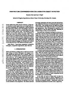
In our experiments, we set γh = 3.4, γl = 0.8 ∗ γh and L = 16. 2.2 MTI Algorithm Results Figure 5.1 shows the object detection result for frame 200 and 300 on an IR sequence (IRseq10) for the case of people walking at far away distance. Eventhough the width of the objects (people) is 2-3 pixels, the algorithm correctly detects and tracks them. In this sequence, the sensor was stationary and its direction was fixed. Figure 5.2 shows the detection of a moving vehicle for frames 160 and 250. In this case sensor pans and stops and is quickly able to find the object again. Hence, the algorithm is capable of recovering after sensor panning motion. As a comparison with background subtraction techniques, Fig. 5.3 shows the result using background subtraction based on non-parametric background modelling [2] on IRseq10. We can see that there are a lot of false detections whose sizes are same or even greater than the object size. So, the objects cannot be detected reliably. Also background subtraction techniques need some number of frames for background modelling before they can start the detection process. Figure 5.4 shows the ROC curve for the MTI algorithm for different IR sequences for γh varying from 3.0 to 5.5. The detection percentage is calculated as the ratio of object detections in all frames and the total objects
Chapter 5 Moving Object Detection and Compression in IR Sequences
157
Fig. 5.1. Object Detection: Frame 200 and 300 of IRseq10 along with detected objects
Fig. 5.2. Frame 160 and 250 of a moving vehicle IR sequence along with detected objects (sensor recovering after panning motion)
actually present in all frames. The false alarms percentage is calculated as the ratio of the false alarms in all frames and the total objects in all frames. Since we do not have ground truth, it was generated manually as follows. For all the sequences considered, the objects are far away and are moving approximately parallel to the image plane with uniform speed. The objects locations were hand-picked every thirty frames and are interpolated in between assuming constant object velocity. Table 1 shows the effect of parameter L on detection rates and false alarms for different sequences.
158
Namrata Vaswani et al.
Fig. 5.3. Detection Result using background subtraction on IRseq10 ROC for MTI algorithm 1
0.9 IR seq 1 IR seq 2 IR seq 9 IR seq 10 IR seq 14
0.8
0.7
Detection %
0.6
0.5
0.4
0.3
0.2
0.1
0
0
0.1
0.2
0.3
0.4
0.5 0.6 False Alarms %
0.7
0.8
0.9
Fig. 5.4. ROC curve for the MTI algorithm for different IR sequences
1
Chapter 5 Moving Object Detection and Compression in IR Sequences
159
Table 1. Effect of parameter L on Detections and False Alarms for various IR sequences Sequence L Detections(%) False Alarms(%) IRSeq1 IRSeq1 IRSeq9 IRSeq9 IRSeq2 IRSeq2
8 16 8 16 8 16
98.33 99.83 97.70 97.70 99.80 99.60
13.8 28.3 2.24 0.05 32.09 57.33
The MTI algorithm has been implemented on a Dual Pentium 550MHz personal computer. It can perform moving object detection for 974×436 image sequences at a sustained rate of twelve frames per second (including reading data from hard drive and sending image to video display). The algorithm has been tested on fourteen 974 × 436 × 3600 sequences with objects at various distance, moving speed, moving direction, and motion patterns, and with different number of moving objects. From the ROC curves (Fig. 5.4) and Table 1, we see that the MTI algorithm gives good results (high detection rate and very low false alarm rate) on almost all of the test sequences with no running parameters to be adjusted. 2.3 Short Range Object Detection The problem of object detection is formulated as one of segmenting an image function using a measure of its local singularity as proposed in [1]. The method combines the problem of stabilization, object detection and tracking into a single process when interframe motions are restricted to lateral translations or tilts and scale changes, and has the advantage of exploiting these sensor motion constraints for performing simultaneous activity detection and stabilization. The algorithm makes use of the Holder exponent of a hybrid capacity (derivative of Gaussian along the X and Y axis). Using this measure, Lipschitz signatures which reflect the singularity of the image function along each spatial axis are defined. The Lipschitz signatures are used for detection and tracking of objects. The proposed measure is obtained by applying the operators Gx,σ and Gy,σ to the images which are the derivatives of the Gaussian applied along x and y axes, respectively. The Lipschitz signatures can then be defined as the projection of the these measure along the x and y axes. The main assumption of the algorithm is that the ”active regions” of the image exhibit some higher level of singularity in the Lipschitz signatures. In other words, the singularities can be detected and tracked over time. The algorithm is robust to image scale variations and can handle multiple moving objects. It also involves projection along spatial axis and hence can be done in real time. Spatio-temporal information on the objects in the scene can also be inferred.
160
Namrata Vaswani et al.
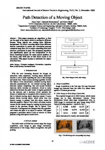
3 Best View Selection As mentioned earlier, the best view selection is not required when the detected object chip is small in size (few pixels), but becomes important in case object chip is large and the object pose changes from time to time. Three different techniques were tried for best view selection. We work on the assumption that the side view is the ”best view” since it has most of the identifiable features (See Fig. 5.5). Eigenspace classification has successfully been used for pose detection [3] and face recognition applications [4][5]. In the first approach, we formulate the best view selection problem as a pose matching problem in eigenspace. Another approach to best view selection would be to wait while the object size keeps increasing (it is approaching the sensor) and transmit the largest sized image or transmit the last frame before the object takes a turn. This can done by estimating the Focus of Expansion (FOE) which can be used to calculate the velocity direction. Since both techniques mentioned above are computationally intensive, they are not suitable for real-time hardware implementation. The eigenspace technique also suffers from the drawback that it is not generalizable, i.e. to use it for a different type of vehicle it would require a new training phase. It works well only when similar objects are available in its training database. Hence, the third approach, a size based detection method was finally implemented. In what follows, we describe these techniques in detail. 3.1 Eigenspace Classification This technique is useful for best view selection when there are multiple sensors capturing an object from different orientations and a database of multiple views of the object is available. In our experiments we have used multiple views of tanks taken from different directions. A view closest to the side view is classified as the best view.
Fig. 5.5. Tank2 (side view)
Chapter 5 Moving Object Detection and Compression in IR Sequences
161
Algorithm Construct an eigenspace using images of tank in various orientations. Place the camera at forty-five degree spacings around the tanks to obtain eight possible views of each tank. Obtain the mean image of each of the eight orientations and save its coordinates in eigenspace. For a query image, classify it in eigenspace and calculate the distance from each of the orientations using a distance metric. Since the required data for doing this was not available, we constructed an eigen space using all the tank images available and obtained class means corresponding to front, side and back views. On classification of a query image, it got mapped to the correct class most of the times. Eigenspace Construction Instead of directly obtaining the eigenvectors of an N 2 ×N 2 covariance matrix, the first M (M is the number of training vectors) eigenvectors can be obtained by first calculating the eigenvectors of an M × M covariance matrix of the transpose of the image data and then obtaining the image eigenvectors by taking linear combinations of the training images weighted by the eigenvector component as described in [4][5][6]. Scale and Intensity Invariance Since eigenspace classification is sensitive to scale variations, all images were scaled down to a fixed size before classifying and since the image chip contained the tank only, scaling down the image to a fixed size implied obtaining the tank image of a fixed size. Both for eigenspace construction and classification, the images were normalized by their total energy. Distance Metrics The distance metric can either be the simple Euclidean distance(ED) or the distance along each component normalized by the corresponding eigenvalue (ND). The latter gives better results since it gives more weight to those directions where the noise variance is lower. A better solution is to obtain variance along each component in each class and calculate the distance from a particular class using those eigenvectors which have low variance in that class but overall high variance in eigenspace. For scaling the distance from class k, the variance in class k is used rather than the global eigenvalue for scaling. In this way, the intra-class variance can be suppressed while the inter-class variance can be emphasized. We call this measure the Class Normalized Distance (CND). All the three distance metrics for some sample images are tabulated in Table 2. It can be seen from the results that the CND is the best metric for classification for the reason stated above.
162
Namrata Vaswani et al. Table 2. Eigenspace Classification Results Class
Class Normalized Euclidean Normalized Distance(CND) Distance(ED) Distance(ND)
tank2 tank6 tank9 btank12 sftank5
4 15 15 30 17
10 20 19 44 21
24 35 28 56 31
3.2 Focus of Expansion Estimation The Focus of Expansion is the point in the image sequence of a moving body from which all the motion vectors appear to diverge. The FOE may not always lie inside the image boundary. Mathematically, the FOE(Xf ,Yf ) is define as Xf =
Tx Tz
(15)
Yf =
Ty Tz
(16)
where Tx ,Ty , Tz are the translational motion vectors. Therefore, assuming the ground is the X-Z plane, the direction of motion (velocity angle) of the tank is given by Vx Tx θ = tan−1 = tan−1 = tan−1 Xf (17) Vz Tz A modification of the partial search technique for FOE estimation developed by Srinivasan in [7] was used. The equations to be solved are u(x, y) = −(x − xf )h(x, y) + xyωx − (1 + x2 )ωy + yωz
(18)
v(x, y) = −(y − yf )h(x, y) + (1 + y 2 )ωx − xyωy − xωx
(19)
where u(x, y) and v(x, y) are the optical flow estimates at (x, y), xf , yf are the x and y coordinates of the FOE in the image(pixel) coordinates, h(x, y) is the inverse of the depth at point (x, y) and ωx , ωy , ωz are the x, y and z direction rotations. The FOE estimation algorithm requires calculation of optical flow which is done using the overlapped basis functions technique developed by Srinivasan and Chellappa [8]. The FOE in the world coordinates is given by Xf =
xf + xof f set − (N − 1)/2 f
(20)
which is used for direction of motion calculation in (17). In the modified partial search FOE estimation technique, we use only the optical flow estimates of the part of the image containing the moving object
Chapter 5 Moving Object Detection and Compression in IR Sequences
163
since the flow estimates of the background are unreliable. Since the size of the image for which optical flow is available is smaller, the FOE is also searched over a smaller region. This speeds up the FOE calculation. Also, the FOE estimate of the previous frame can be used to select an initial offset for the FOE in the current frame to speed up the FOE calculation over successive frames. The direction of motion is estimated at regular intervals and we keep waiting if the tank is approaching towards the camera. The frame at which the tank takes a turn away from the camera or the tank’s size increases above a certain threshold could be chosen as the ”best view” in this approach. 3.3 Size based Best View Selection Since the application requires best view selection and compression to be done in real-time on hardware with low computing power, we need very simple techniques for best view selection. Thus the final algorithm that was implemented simply waits till the size of the image chips exceeds a pre-defined threshold. If the size starts decreasing, it simply chooses the maximum size frame in the last 90 frames and sends it. Actually a single frame buffer is used to store the maximum sized chip in the last few frames and as soon as the size starts decreasing or increases beyond the threshold, the stored frame is compressed and transmitted. The algorithm rejects chips which are very close to the image boundary (the tank may not be complete). Spurious frames (produced as a result of wrong object detection) are also rejected based on thresholding the height to width ratio. 3.4 Best View Selection Results In this section, we present the results of best view selection using the three approaches discussed above. Eigenspace Classification An eigenspace of front, side and back views of various tanks is constructed and the class means for each class are precalculated. In Table 2 results for distances from the perfect side view (”tank2”) class are shown. Figure 5.6 shows the mean image of the tank2 class. Distance of a query tank2 image (side view, see Fig. 5.5) is a minimum. Distance of tank6 (sideback view) shown in Fig. 5.8 is higher than tank2 but lower than tank12 (back view) shown in Fig. 5.7. Hence tank2 is the ”Best View” in this case. As can be seen from Table 2, the CND (Class Normalized Distance) has the maximum variation (4 for perfect side view and 30 for back view) and thus it is the best metric for classification among the metrics used. The eigenspace classification is not a very good method for best view selection because it is sensitive to the lighting conditions, the type of IR sensor
164
Namrata Vaswani et al.
Fig. 5.6. Mean Image of the tank2 class
Fig. 5.7. Query Image 3: tank12 (Back view)
Fig. 5.8. Query Image 2: tank6 (Back-side view)
used, and to the scale of the image. If the actual sensor is different from the sensor used in the database, classification could fail. Moreover a very large database of tank images in various poses is required for a robust eigenspace construction which may not be feasible. Focus of Expansion Estimation The FOE estimation algorithm was run on IR video sequences of the tanks. Since most of the tanks are moving almost horizontally in front of the camera in the test sequences, the FOE values are very large (tending to infinity). The FOE in pixel coordinates for a sample sequence is shown in Table 3. The
Chapter 5 Moving Object Detection and Compression in IR Sequences
165
Table 3. FOE Estimates using the optical flow shown in Fig. 5.10 Frame No F OEx F OEy 121 123 125 127 129 131
-244 -369 -201 -253 -553 -583
145 152 140 136 110 110
optical flow estimate for the full Frame 125 is shown in Fig. 5.9. The region of 0
50
100
150
200
0
50
100
150
200
250
300
Fig. 5.9. Optical Flow Estimate of a typical frame (125) for FOE Estimation
significant motion that is segmented out and used for FOE estimation finally is shown in Fig. 5.10. The FOE estimation technique is not very suitable for our application because both optical flow calculation and FOE estimation are computationally intensive. Also for the IR images, the optical flow estimates are not very accurate and as a result the FOE estimates are also not accurate enough. Size Based Best View Selection Figure 5.11 shows a best view selected by this approach.
166
Namrata Vaswani et al. 0
10
20
30
40
50
60
70
80
90 0
20
40
60
80
100
120
140
160
180
200
Fig. 5.10. Segmented Optical Flow Estimate for frame 125 which is finally used in FOE Estimation (Magnified view)
Fig. 5.11. Size based Best View Selection
4 Compression For long range objects, since the detected image chip is already very small, compression is not really necessary. Also since the object chip contrast can be very low compared to the background, it is preferable to just transmit the binary image of the object (instead of transmitting a grey scale one) which itself provides an 8 : 1 compression ratio. If more computational power is available, the binary image could be compressed by run-length coding else just the raw bits can be transmitted. For objects at short range (which are large), the image chip chosen by the ”Best View Selection” algorithm has to be compressed before transmission.
Chapter 5 Moving Object Detection and Compression in IR Sequences
167
Since the available channel bandwidth is low, we have tried to develop compression schemes which can provide very high compression ratios while at the same time maintaining a reasonable image quality. Since the algorithm is to be implemented in real-time using limited computing hardware, the computational complexity should be low. We have developed real-time algorithms for image compression in the wavelet domain. We first provide a background of existing image compression schemes and discuss the theoretical background for wavelet transforms and the compression techniques. Following that, we discuss the compression schemes implemented and compare against other techniques. We compare our scheme, Combined Zerotree and DPCM Coding against three existing schemes all of which have low computational complexity, viz. Scalar Quantization (SQ), Zerotree coding and DPCM coding. The more efficient compression schemes like JPEG and LZW are not compared here because they have a much higher computational cost associated with their implementation. We then provide a performance analysis of the coding schemes. Finally experimental results are provided followed by computational cost analysis. We use PSNR (Peak Signal to Noise Ratio) which is a standard metric for image compression schemes to compare de-compressed image quality. 4.1 Previous Work A wavelet zerotree coding scheme for compression is presented in [9] but since it uses Vector Quantization (VQ), it cannot be used for our application due to high computational cost. Reference [10] presents an embedded predictive wavelet image coder. But it uses arithmetic coding which is not suitable for implementation on a embedded processor such as Hitachi’s SH4. So we have developed algorithms using the Haar wavelet transform followed by non-iterative zerotree coding [9] and 2D-DPCM for all subbands. The computational complexity of these algorithms is only marginally higher than simple scalar quantization (SQ) of the entire image. 4.2 Wavelet Transform Properties The wavelet transform is an atomic decomposition that represents a signal in terms of shifted and dilated versions of a prototype bandpass wavelet function and shifted versions of a low pass scaling function. In discrete time, the bandpass wavelet function is a high pass filter at different scales and the scaling function is a low pass filter. The image is low pass and high pass filtered first along rows and then along columns to generate LL, LH, HL and HH images each of which is subsampled by two. This process is repeated on the subsampled LL image. The wavelet transform has the following properties which make it suitable for compression. •
Multiresolution: The image is decomposed into wavelets at N scales and only the top few coarsest scales need to be transmitted to obtain a reasonable image quality. Depending on the available channel bandwidth, more
168
•
•
Namrata Vaswani et al.
finer scale coefficients can be transmitted to improve the reconstructed image quality. Entropy Reduction: The wavelet transform of a real image generates a large number of small coefficients (which can be set to zero) and a small number of large coefficients which can be encoded. This property is based on the fact that a real world image will not have information in all frequencies at all points in space. At most points except edges, the higher frequency information is almost zero. Clustering and Persistence: The wavelet transform attempts to decorrelate the image but the decorrelation is not complete (since the filters are constant, not data dependent). There is a residual dependency between adjacent coefficients at the same scale (clustering) and between coefficients in adjacent scales but the same spatial location (persistence). Our coding schemes attempt to remove these correlations in the image.
4.3 A-DPCM for Scaling coefficient(LL) encoding The scaling coefficients (LL subband) contain the maximum information and thus more bits are allocated for its encoding. But it is also the most highly correlated subband and this fact can be exploited to maximize compression. An Adaptive-DPCM scheme is used for encoding the LL subband. The current pixel is predicted based on a linear combination of three causal nearest ˆ is obtained as neighbors. The predicted value of the pixel, X X ˆ = l(Q) ¯ = w. ¯= X ¯Q wk Qk (21) The predictor coefficients w ¯ are calculated to minimize the mean squared prediction error as follows ¯Q ¯ T )−1 E(X.Q) ¯ w ¯ = E(Q
(22)
where X is the pixel to be predicted, Qi are the quantities based on which the pixel would be predicted (in this case the nearest neighbors), and w ¯ are the predictor coefficients. Instead of quantizing the pixel value, the error between ˆ is quantized, which requires fewer the actual and the predicted value (X − X) bits since the error would be much smaller than the original pixel value if the prediction is good. Calculation of LMSE predictor coefficients can be done offline on a set of similar images. 4.4 Zerotree Coding In multiresolution wavelet decomposition, each coefficient Xi , except those in the LL subband and the three highest subbands, is exactly related to 2 × 2 coefficients of the immediately higher subband. These four children coefficients correspond to the same orientation and spatial location as the parent
Chapter 5 Moving Object Detection and Compression in IR Sequences
169
coefficient Xi . Each of the four children coefficients is in turn related to 2 × 2 coefficients in the next higher subband and so on. These coefficients are collectively called the descendants of the parent Xi . All coefficients with magnitude less than threshold T are called insignificant coefficients and their collection is known as a zerotree. In order to obtain a real-time implementation [9], the search for insignificant coefficients is started in the lowest frequency subbands except baseband and continued in higher frequency subbands. When a coefficient is decided as insignificant and set to zero, all its descendants are also set to zero. Thus one need to transmit only the escape code for the zerotree root vector besides encoding the non-zero coefficients. The zerotree root positions at each scale can be encoded efficiently using the Run-length Coding(RLC). The non-zero coefficients can be scalar quantized and transmitted. This type of simple threshold based zerotree coding, RLC and SQ are computationally simple algorithms for hardware implementation. However, it is possible that there are significant descendants even though their parent is insignificant. These mispredictions are inevitable in a noniterative search method but the conditional probability of this happening is very small as discussed in [9]. The misprediction error can be reduced by predicting the value of a ”zero” coefficient based on its nearest non-zero neighbors (causal and non causal) while decoding. 4.5 DPCM on Wavelet Coefficients The zerotree coding exploits the persistence property of wavelet coefficients. But there is also a residual correlation in the high frequency subbands especially the LH and the HL bands with horizontal and vertical neighbor respectively. Hence applying a A-DPCM scheme like that discussed for the LL subband can give additional compression. Also while obtaining the prediction value for the current pixel we can exploit both clustering and persistence properties, i.e. obtain a prediction for the current pixel based on its vertical (for HL) or horizontal neighbor(for LH) and its parent coefficient. Again as in the case of the LL subband, the predictor coefficients can be calculated offline for a sequence of similar images using (22). In this case the predictors are the parent coefficient at the same spatial location and the horizontal or vertical neighbor. This scheme is motivated by a similar scheme discussed in [10] for visual images. 4.6 Compression Schemes Four different schemes for encoding the wavelet coefficients were compared. In all cases the LL subband was encoded using the A-DPCM scheme discussed in Sect. 4.3.
170
Namrata Vaswani et al.
Scalar Quantization This scheme involves scalar quantization (SQ) of the wavelet coefficients and DPCM encoding of the LL coefficients. Variable bits are allocated to the subbands based on their variances as discussed in [9]. Zerotree Coding Zerotree coding is applied as discussed in Sect. 4.4. This not only gives a significantly reduced bits per pixel (BPP) value than the SQ (as expected), but also gives reduced MSE value compared to SQ. The reason is that the quantization error is higher than the thresholding error for high frequency subbands which are coarsely quantized. 2D Predictive DPCM on Wavelet Subbands Only DPCM coding is applied as discussed in Sect. 4.5 with no zerotree coding. The performance of this scheme is bad because the ”noisy data” close to zero, cannot be predicted correctly and hence the prediction errors obtained are sometimes larger than the original pixel value. Hence the MSE is significantly higher. Combined Zerotree and DPCM coding We propose to combine zerotree coding and the DPCM encoding (ZT/DPCM) of wavelet coefficients to achieve maximal compression. First a simple zerotree coding is applied to the subbands. This is followed by DPCM coding of the ‘non-zeroed’ coefficients. The value of a ‘zeroed’ neighbor is predicted as follows. If we predict Cx,y based on Cx−1,y which is ‘zeroed’ and the zeroing threshold is T , we estimate Cx−1,y as follows S = Cx−2,y + Cx−1,y−1 0 if S = 0 Cˆx−1,y = −T if S < 0 +T if S > 0 This is based on the assumption that since the next coefficient is non-zero,the previous one would be close to the threshold. DPCM combined with zerotree coding works much better because the noisy coefficients have been set to ‘zero’ and we do not try to predict their value. The prediction model is applicable only to those subbands for which enough (> 2) bits have been allocated and the prediction error energy obtained while calculating the predictor coefficients is less than 25% of the subband energy. For other subbands, SQ is used.
Chapter 5 Moving Object Detection and Compression in IR Sequences
171
4.7 Performance Analysis The aim of any compression scheme is to minimize the mean squared error (maximize the PSNR) and the entropy per pixel (entropy rate, ER). In SQ, each pixel is coded independently and the correlation in the image is not exploited. So the entropy rate is higher. Entropy rate will be minimized if each pixel is coded based on all past pixels on which it depends, i.e. (for a 1D signal) h(Xn ) > h(Xn |Xn−1 ) > h(Xn |Xn−1 , ..., 1) (23) If we assume a one step Markov model, h(Xn |Xn−1 ...1) = h(Xn |Xn−1 )
(24)
For 2D data (assuming a Markov Random Field model), this translates to Xn,n depending only on Xn−1,n and Xn,n−1 . The quantization MSE will be minimized for a given bit rate if the mean square value of the quantity to be quantized is minimum. Hence instead of quantizing Xn,n , in 2D Predictive DPCM, we predict a value (Xˆn,n ) based on past values and quantize the difference (Xn,n − Xˆn,n ) . Xˆn,n is calculated as discussed in (21) to minimize E[Xn,n − Xˆn,n ]2 and hence the quantization MSE over all linear estimators. Also for a given quantization step size (fixed MSE), reduced data variance means reduced entropy. In zerotree coding, the PSNR is higher than SQ because the zeroing error is lower than the quantization error for high frequency subbands which are coarsely quantized. Zeroing also reduces entropy since the number of symbols to be compressed is reduced. The 2D MRF model with second order dependencies (correlations) fits well for the LL subband but does not fit well for the wavelet subbands and the prediction fails completely for very small values (only noise). This is the reason why DPCM on wavelet subbands gives the worst PSNR values. Combined zerotree and DPCM (ZT/DPCM) gives best results in terms of PSNR and entropy rate. The noisy coefficients are zeroed and hence not predicted and thus the quantization error remains low. Because of LMSE prediction, the entropy is minimum and zerotree coding further reduces the entropy rate by reducing the number of symbols to be coded. 4.8 Image Compression Results Various types of low pass and high pass filters satisfying the prefect reconstruction property can be used. In our implementation, the Haar transform is used because of its simplicity and ease of hardware implementation. Using a longer length filter will not be useful because the low pass filter will tend to average over a very large area and thus loose the localization property of wavelet transforms. The Haar wavelet is built using a two tap low pass filter [1, 1] and a two tap high pass filter [1, −1].
172
Namrata Vaswani et al.
Figure 5.5 shows the original tank2 image and Fig. 5.12 shows the compressed tank2 images using Combined Zerotree/DPCM coding and Zerotree coding.Table 4 shows the compression results for two sample IR images and the Lena image. Table 4. The bpp, PSNR[10 log10 2552 /M SE] and Entropy for three sample images using Zerotree (ZT), Zerotree & DPCM (ZT/DPCM), Scalar Quantization (SQ) & only DPCM coding schemes Image Coder
Total PSNR Entropy RLC BPP (Non-zero) BPP
tank2 ZT/DPCM ZT tank12 ZT/DPCM ZT lena ZT/DPCM ZT SQ DPCM
0.5628 0.5628 0.5232 0.5232 0.5066 0.5066 0.7947 0.7947
31.73 31.61 31.75 31.65 29.40 29.30 13.07 25.34
0.0920 0.2112 0.0880 0.2045 0.0851 0.1542 0.3156 0.1508
0.2757 0.2757 0.2649 0.2649 0.2286 0.2286
Fig. 5.12. Compressed tank2 by (a) Combined zerotree & DPCM coding (b) Zerotree coding
Chapter 5 Moving Object Detection and Compression in IR Sequences
173
The results have been obtained by allocating a total of 0.5 BPP to various subbands proportional to the logarithm of their variances. Since for this low value of BPP, the lowermost subbands get negative bits allocated to them (which are set to zero), the actual BPP obtained is higher than 0.5. In Table 4 we have compared the total BPP, PSNR, BPP for RLC coding and entropy rate for three different images (two from IR sequence and the Lena image). The entropy rate is the minimum bits/pixel that can be theoretically achieved for the image. Due to hardware constraints we have not implemented any form of entropy coding (Arithmetic/Huffman). As can be seen from the values of RLC BPP, almost half the bits are used up in encoding the zerotree information. More efficient binary encoding schemes can be employed to reduce this value and this could considerably improve the BPP. Also, in most cases the combined zerotree and DPCM scheme gives the best results both in terms of PSNR values and entropy. In some cases like the Lena image, the PSNR is higher for simple zerotree coding but the entropy of the combined scheme is less. Ideally, one would assume that applying a DPCM encoding would cause a significant reduction in PSNR. This is definitely true for the LL subband but the reduction for higher frequency subbands is not so much because of lesser correlation. Another reason is the uncertainty in predicting the value of a pixel based on a neighboring ”zeroed” pixel. We are experimenting with better methods to improve the prediction model for combined zerotree and DPCM encoding. The BPP without zerotree coding is consistently higher for all the images and hence the zerotree coding is advantageous even though half the BPP is used up in RLC coding of the zerotree. Also surprisingly, the PSNR for SQ is lower than for zerotree coding even when the BPP is higher. The reason for this is that the quantization error in SQ is higher than the zeroing error for the high frequency subbands which are coarsely quantized. From Table 4, we observe that DPCM encoding without zeroing is the worst scheme. This is because a lot of the coefficients below the zeroing threshold in the high frequency subband are actually ”noise”. Thus in DPCM we are trying to predict the value of these ”noise” pixels or use them to predict other pixels and hence the predictions are very bad thus leading to a higher PSNR. Hence the DPCM model fails in the absence of zerotree coding, while it provides a reasonably good model for the image when combined with zerotree coding. 4.9 Computational Complexity: Hardware issues The entire coding scheme is computationally very simple. The Haar wavelet transform involves a single addition operation per pixel. Zerotree coding requires one comparison to a threshold (per pixel) and a multiplication by two (a shift operation) to calculate the descendant position. The DPCM operation involves three real multiplications and two additions to calculate the predicted vale and one subtraction to obtain the error. Run-length coding is
174
Namrata Vaswani et al.
again a counting operation requiring one addition per pixel. Thus the additional cost over scalar quantizing the entire image is (which is the minimum one has to do to compress an image) is three multiplications and a few additions per pixel. For an N 2 xN 2 image with a three level wavelet decomposition, the additional cost for our scheme is given by ACHaar = (N 2 + N 2 /4 + N 2 /16)CA 2
2
(25)
2
(26)
ACRLC = N CA
(27)
ACZeroing = (N + N /4 + N /16)(CC + CS ) 2
2
ACDP CM = N (3CM + 3CA )
(28)
where AC is additional cost. CA is the cost for one addition, CM is the cost for one multiplication, CC is the cost for one comparison, and CS is cost for one shift (multiply by two) operation . Since comparison and shift are single operations, CC = CS = 1. Hence, total additional cost is AC = (N 2 + N 2 /4 + N 2 /16)(CA + 2) + N 2 (3CM + 4CA )
(29)
5 Performance Evaluation of Algorithms We have developed a C/C++ implementation of the object detection and compression/decompression algorithms. The C/C++ implementation of image compression part of the system currently uses zero-tree coding with SQ and RLC. Performance evaluation of the C/C++ code was done using the Hitachi’s SH4–7751 microprocessor. SH4–7751 is a high performance superscalar RISC microprocessor designed for embedded applications. Some of the features of SH4 include 167MHZ clock frequency, upto 360 MIPS capability and on-chip cache for instruction and data. More information on SH4 can be found at http://semiconductors.hitachi.com. We evaluated the code performance using the Hitachi Embedded Workshop (HEW) which is an SH4 simulator provided by Hitachi. The results were obtained using the Profile utility of HEW. Note that these results are obtained by directly cross-compiling the C code using Hitachi’s cross-compiler. Hence, certain features of SH4 architecture (such as floating point unit) which can enhance real-time performance are not used. In practice, the performance can be improved by designing the assembly language code for computationally expensive procedures so as to take advantage of such features of object microprocessor. The performance results of the algorithms in terms of code size, run-time memory requirement and instruction cycles on SH4 are as follows. 5.1 MTI Algorithm The code size required for the MTI algorithm was 9.8 KB. For an input frame size of 120 × 160 maximum run-time memory required was 1.086 MB. Cycles required per frame were equal to 8.5M which corresponds to 19.54 frames per second (30 fps frame rate).
Chapter 5 Moving Object Detection and Compression in IR Sequences
175
5.2 Image Chipping Algorithm Motion Detection and Best View selection For motion detection using technique described in Sec. 2.3 and best view selection, the code size required was 16 KB. The run-time memory required for frame size of 240 × 320 was 2.4MB and the processing frame rate (for 120 × 160 frame size) was 4-5 frames per second. Compression The compression part of algorithm required a code size of 30.5 KB. For a typical image chip of size 60×120, run-time memory required was 0.75MB and cycles on SH4 needed to compress the images was 31.5M which corresponds to run-time of 0.188 sec. The run-time is calculated as Cycles/Clock frequency. Decompression Decompression required a code size of 21.5 KB and for a typical image chip of size 60 × 120, run-time memory required was 0.75MB. Note that this memory requirement will increase with chip size. Table 5 gives the instruction cycles required for different PSNR values of reconstructed sample tank chip. Table 5. Cycles and run-time required for decompression of a sample target chip of size 60 × 120 for different PSNR PSNR(db) Cycles(million) Runtime on SH4(sec) 30.21 34.36
20.73 21.00
0.120 0.125
6 Conclusions A novel variance analysis based algorithm has been presented for moving object detection. The algorithm is especially suitable for detection of long range, small, slow moving objects. An initial test on several IR sequences has revealed high detection rates with low false alarms for vehicles at distances of several kilometers. The algorithm is robust and requires no tuning of parameters by the operator. For object at short distances, technique based on detecting and tracking image singularities have been discussed. Also for objects at short range, methods for best view selection and compression were presented. Three different approaches to the best view selection problem were compared. The
176
Namrata Vaswani et al.
approach based on classification in eigenspace is suitable when multiple views of the same object are available but has limitations when significant scale and illumination variations are present. The FOE estimation approach would be a useful method for direction of motion calculation but is computationally expensive. The size based technique is the fastest and gives reasonable results and is used in our implementation. A new scheme combining non-iterative zerotree coding with 2-D DPCM for LL and for the high frequency subbands was presented. This method gives better results than simple scalar quantization and simple zerotree coding both in terms of BPP and PSNR at a marginally increased computational cost. The algorithms were implemented in C and their performance results on SH4 processor were presented. The image compression results can be further improved by using some form of entropy coding (since the entropy rate of our scheme is significantly lower) and by replacing the run length coding method with more efficient binary coding techniques. Also the zeroing thresholds can be calculated for the required PSNR values.
References 1. Shekarforoush H, Chellappa R (2000) A Multi-fractal Formalism for Stabilization, Object Detection and Tracking in FLIR Sequences. International Conference on Image Processing 3:78-81 2. Elgammal A, Harwood D, Davis LS (2000) Nonparametric Background Model for Background Subtraction. Proc 6th European Conf Computer Vision 2:751– 767 3. Murase SK, Nayar SK (1995) Visual Learning and Recognition of 3-D Objects from Appearance. IJCV 14:5–24 4. Turk M, Pentland A (1991) Eigenfaces for Recognition. J Cognitive Neuroscience 3:71–86 5. Turk M, Pentland A (1991) Face Recognition Using Eigenfaces. Proc IEEE Conf on Computer Vision and Pattern Recognition 586–591 6. Sirovich L, Kirby M (1987) Low Dimensional Procedures for the Characterization of Human Faces. Journal of Optical Society of America 4:519–524 7. Srinivasan S (2000) Extracting Structure from Optical Flow Using Fast Error Search Technique. Int Journal of Computer Vision 37:203–230 8. Srinivasan S, Chellappa R (1999) Noise-resilient Optical Flow Estimation Using Overlapped Basis Functions. Jl Optical Society of America 16:493–509 9. Paek SK, Kim, LS (2000) A Real-time Wavelet Vector Quantization Algorithm and its VLSI Architecture. IEEE Trans on CSVT 10:475–489 10. Buccigrossi RW, Simoncelli EP (1999) Image Compression via Joint Statistical Characterization in the Wavelet Domain. IEEE Trans on Image Processing 8:1688–1700 11. Shapiro JM (1993) Embedded Image Coding Using Zerotrees of Wavelet Coefficients. IEEE Trans on Signal Processing 12:3445–3462 12. Burt P, Adelson E (1983) The Laplacian Pyramid as a Compact Image Code. IEEE Trans on Comm 4:337–343
Chapter 5 Moving Object Detection and Compression in IR Sequences
177
13. Podilchuk C, Jayant N, Farvardin N (1995) Three Dimensional Subband Coding of Video. IEEE Trans on Image Processing 2:125–139 14. Vaswani N, Chellappa R (2001) Best View Selection and Compression of Moving Objects in IR Sequences. Proc ICASSP 3:1617–1620 15. Cutler R, Shekhar C, Burns B, Chellappa R, Bolles R, DavisL (1999) Monitoring Human and Vehicle Activities Using Airborne Video. 28th Applied Imagery Pattern Recognition Workshop Washington, D.C. 16. Davis L, Fejes S, Harwood D, Yacoob Y, Hariatoglu I, Black M (1998) Visual Surveillance of Human Activity. Asian Conference on Computer Vision 267–274 17. Haritaoglu I, Harwood D, Davis L (1998) W4: A Real Time System for Detecting and Tracking People in 2.5D. Proc 5th European Conf on Computer Vision 877-892 18. Li B, Chellappa R (1999) Dynamic Object Identification and Verification from Video. Proc ICASSP, Arizona 19. Rajagopalan AN, Burlina P, Chellappa R (1999) Detection of People in Image. IEEE Conf on Neural Networks 4:2747–2752 20. Zheng Q, Chellappa R (1993) Motion Detection Using Image Sequences Acquired From a Moving Platform. Proc ICASSP, 5:201–204 21. Zheng Q, Chellappa R (1995) Automatic Feature Point Extraction and Tracking in Image Sequences for Arbitrary Camera Motion. Intl Journal of Computer Vision, 15:31–76