Full connectivity is achieved by enabling stations to merge their row and column ..... The diagonal stations also merge for about 10% of the time. One might ...
Multi-Access Mesh (Multimesh) Networks Terence D. Todd McMaster University Hamilton, Ontario L8S 4K1 Canada
Abstract
Ellen L. Hahne Bell Laboratories Murray Hill, NJ 07974-0636 USA
This paper introduces the multi-access mesh (or multimesh) network. Stations are arranged in a two-dimensional mesh in which each row and column functions as a conventional linear LAN or MAN subnetwork. Full connectivity is achieved by enabling stations to merge their row and column subnetworks, under the coordination of a Merge Control Protocol. A twodimensional token-passing protocol is considered, and a more complex protocol motivated by max-min fairness is also presented. Like conventional LANs and MANs, the multimesh requires no transit routing or store-and-forward bu�ering. The multimesh is a generalization of the token grid network [1]. Using analysis and simulation, we study the capacity of multimeshes constructed of token rings and slotted rings, under uniform and nonuniform loads. A multimesh can support much higher throughput than conventional linear LAN and MAN networks with the same transmission hardware. Moreover, the multimesh capacity grows with the number of stations. We also present a healing mechanism that ensures full network connectivity regardless of the number of failed stations.
This paper appears in IEEE/ACM Transactions on Networking, Vol. 5, No. 2, April 1997, pp. 181-189.
Multi-Access Mesh (Multimesh) Networks Terence D. Todd Communications Research Lab., Rm. 204 McMaster University Hamilton, Ontario L8S 4K1 Canada
Ellen L. Hahne Bell Laboratories 600 Mountain Ave., Rm. 2A-234 Murray Hill, NJ 07974-0636 USA
Abstract This paper introduces the multi-access mesh (or multimesh) network. Stations are arranged in a twodimensional mesh in which each row and column functions as a conventional linear LAN or MAN subnetwork. Full connectivity is achieved by enabling stations to merge their row and column subnetworks, under the coordination of a Merge Control Protocol. A two-dimensional token-passing protocol is considered, and a more complex protocol motivated by max-min fairness is also presented. Like conventional LANs and MANs, the multimesh requires no transit routing or store-and-forward bu�ering. The multimesh is a generalization of the token grid network [1]. Using analysis and simulation, we study the capacity of multimeshes constructed of token rings and slotted rings, under uniform and nonuniform loads. A multimesh can support much higher throughput than conventional linear LAN and MAN networks with the same transmission hardware. Moreover, the multimesh capacity grows with the number of stations. We also present a healing mechanism that ensures full network connectivity regardless of the number of failed stations.
1
Introduction
Most Local Area Network (LAN) and Metropolitan Area Network (MAN) products have been based on linear topologies such as bi-directional and uni-directional buses and rings [2, 3], because very simple and economical station attachment units may be realized. In a typical bus or ring adapter, for example, little or no transit bu�ering is necessary. The maximum throughput of linear rings and buses is severely restricted by the data rate of the shared channel. It would be much more desirable if the network capacity grew with the number of stations. To implement such a design, a network topology must be used that permits multiple concurrent packet transmissions. Unfortunately, in existing mesh networks, the station simplicity of a bus or ring LAN must be sacri ced to achieve this improved performance. For example, in multihop networks [4, 5], high-speed transit routing and bu�ering and associated controls must be provided at each station. To simplify the station design, de ection routing may also be used [6]. In a de ection-routed network, transit bu�ering requirements are reduced in the station by misrouting packets when multiple packets contend for
the same outgoing link. This, however, generates a need for resequencing bu�ers at the destinations to recover from misordering due to de ections. In both cases the station cost may be much higher than in conventional ring and bus networks. This paper introduces a network design called the multiaccess mesh or multimesh, in which stations form a two-dimensional grid. Each row and column can function as a separate one-dimensional subnetwork. The Subnetwork Media Access (S-MAC) protocols used on these row and column subnetworks are conventional multiaccess protocols. To enable communication among di�erent rows and columns, each station can merge its row and column subnetworks into a single subnetwork on which the same S-MAC protocol is used. A Merge Control Protocol (MCP) coordinates the merging and decoupling of row and column subnetworks. Because many subnetworks may be active at once, a multimesh can support much higher throughput than conventional linear LAN and MAN networks with the same station transmission hardware. The complex routing, ow control and bu�ering procedures of other store-and-forward and de ection-routed mesh designs are not required. The multimesh is a generalization of the token grid network [1].
2
Topology
Like dual-bus [2] and dual-ring [3] stations, multimesh stations have physical attachments for two media access subnetworks. These stations are arranged in a two-dimensional grid with and
M
columns. (For convenience,
N
=
M
N
rows
in this paper.) Every row and column has its own
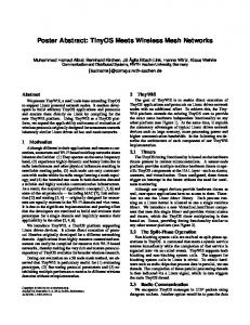
media access subnetwork, and each station is attached to its row and column subnetworks. The subnetworks might be CSMA/CD buses, token buses, token rings, or slotted rings [2, 3, 7]. (Similar topologies have been used in [5, 6].) A 4x4 ring multimesh is shown in Fig. 1, with each station identi ed by its row/column index ( ). r; c
In a multimesh, there are two basic con gurations for each station. In the double-subnetwork (DS) state, a station accesses its two subnetwork attachments separately. The DS state in a ring multimesh is shown in Fig. 2a. Fig. 3 shows a ring multimesh with all stations in their DS con gurations. In this situation, simultaneous transmission may be achieved on all row and column 2
subnetworks, but communication is only possible between stations on the same row or column. Full network connectivity is achieved as follows. Each station can merge its two subnetworks by assuming the single-subnetwork (SS) con guration. The SS state for a station in a ring multimesh is depicted in Fig. 2b. An example is illustrated in Fig. 4, where station (1 2) has entered the SS ;
state, thus merging row 1 and column 2. The result is a single subnetwork (a ring in this example) that includes all stations that were attached to the two original ones. (See [8, 9] for similar merging concepts.) Bus subnetworks can also be merged. For instance, a station can merge two DQDB [2] subnetworks (each a logical dual-bus network built atop physical rings) by declaring itself head and tail of each DQDB, then joining the two DQDBs end-to-end. A station can merge two bi-directional buses by retransmitting on one bus whatever it receives on the other bus; to obviate bu�ering at the merging station, the S-MAC protocol should guarantee that only one station in the entire merged subnetwork is transmitting at a time. For example, in a CSMA/CD [2] multimesh, when the merging station hears a transmission starting on one bus and is repeating it on the other bus, if this collides with a nascent transmission on the second bus, then the merging station should force a collision on the rst bus to keep the two synchronized. In a multimesh it is important to note that the subnetwork selection that occurs during mergings is performed at the media access layer and is transparent to the higher layer routing protocols.
3
Basic Merge Control Protocol
This section presents a basic token-passing protocol to ensure that subnetwork mergers are performed e�ciently and without con icts. Each row subnetwork and each column subnetwork has its own token, which is passed among the stations on that subnetwork. Whenever station ( ) r; c
receives the column- token, the station seizes the column token, then waits to seize the row- token c
r
also. Once holding both tokens, the station is permitted to merge its row and column subnetworks. The exact timing involved depends on the S-MAC protocol; Sec. 4 will give examples. After an appropriate amount of time in the merging state, station ( ) switches state, decoupling row r; c
3
r
and column c. Again, the timing depends on the S-MAC protocol. The row and column tokens are then released on their respective subnetworks. The token mechanism ensures that a given row can be merged with only one column at a time and vice versa. Over time all row/column mergers are e�ected, thereby providing full connectivity among all stations. There are many possible variations of system operation. For example, depending on the type of subnetworks and protocols used, a station may need to suspend media access activity on its subnetworks before performing a merging or decoupling operation and then reactivate S-MAC activity after the switch. Another variation concerns the transmission of packets whose source and destination stations are on the same row (or column). Such transmission may be permitted when that row (or column) is not merged with any column (or row). Alternatively, such transmission may be prohibited, forcing all communication to take place over merged row/column subnetworks. A third variation, assumed herein, is the use of a reservation mechanism [1] to prevent mergers when there is no tra�c to be sent.
4 Ring Multimesh Examples This section presents two examples of multimeshes, both composed of ring subnetworks, but with di�erent protocols for media access. The rst example, called a token ring multimesh, uses token passing for ring media access. Since tokens are used for both merge control and subnetwork media access, the two sets of tokens are combined into one as in [1]. A station is permitted to transmit onto an unmerged ring whenever the appropriate token is captured. After a column token is captured, it is not released but is held until the row token appears. Once the row token is also seized by the station, it is permitted to transmit a packet onto the row. Then the station switches to the merging (SS) state and initiates media access by releasing a special row/column token onto the newly formed ring. This token is propagated around the merged ring enabling station transmissions. It also carries the identities of the two merged rings so that stations know which packets can be transmitted. When the token nishes its rotation, the merging station seizes it, decouples the two rings, then releases the two individual row and column tokens. 4
The second example, called an Orwell multimesh, is based on the Orwell protocol [7]. The subnetworks are slotted rings with destination slot release. Transmission activity under Orwell is organized into cycles in which each station is permitted to transmit a quota of D slots. A distributed mechanism, using a Reset signal, determines the end of a cycle and authorizes transmission activity for the next cycle. To adapt the Orwell protocol to the multimesh, we insist that all stations on a ring cease transmission at the end of each Orwell transmission cycle. During the ensuing quiet interval, tra�c is cleared from the rings, and the rings can be merged or decoupled. Then the merging station initiates a new Orwell transmission cycle by sending a special RESTART signal using an additional slot header bit. In our simulations in Sec. 6, we assume that stations count Orwell Resets to decide when to switch ring merging con gurations. Speci cally, before a station permits itself to merge its row and column rings, it makes sure that it has seen at least one Orwell Reset on each of these rings individually since the last time it merged them together. Once the rings are merged, the station waits until it sees one Orwell Reset on the merged ring before decoupling it.
5 MCP Throughput, S-MAC Throughput, and Total Throughput This section investigates the throughput performance of multimesh networks. Delay performance of similar networks has already been studied extensively in [1]. For any row, column or merged ring �, let n� denote the number of times communication over the ring is enabled by the MCP during a T -second time interval. Let L� (k) denote the duration of the kth enabling. Then the total normalized MCP throughput over T is de ned by n� 1 XX L� (k ): T
S MCP (T ) �
Rewriting the right-hand side as
� k=1
i
P� n h Pn �
T
1 n�
k=1 L� (k ) �
5
(1)
, assuming ergodicity (i.e., that temporal
and probabilistic averages match), and assuming the averages exist, we have: S MCP
where E
f�g
�
X f� E L� ;
lim S MCP (T ) = T !1
is the expectation operation and f� is the
�
�
f
(2)
g
enabling frequency
of ring �. In the case
where the merge times are xed, i.e., L� (k) = l, the MCP throughput is l times the sum of the merge rates. Let S�S MAC (k; L� (k)), called the usage factor , denote the sum of all successful station transmission times during the kth enabling of ring �, divided by the duration L� (k). The conditional mean, given that L� (k) = l, will be denoted by S�S MAC (l). Note that S�S MAC
�
lim S S MAC (l) l!1 �
is the steady-state capacity normally associated with media access protocols [10]. In an N -station IEEE 802.5 token ring, for example, S S MAC =
1 1 1+ (1+ N )+ token
a
a
, where a is the ratio of total
ring latency to mean packet transmission time, and atoken is the ratio of token transmission time to mean packet transmission time. Using these de nitions, we can write the total throughput including media access overhead as 1 S Total (T ) �
X Xn L�(k) S�S MAC (k; L�(k)): �
T � k=1
�
(3)
Assuming ergodicity and that the averages exist, it can easily be seen that S Total
�
lim S Total (T ) = T !1
X f� E nL� S�S MAC (L�)o : �
�
�
(4)
Various special cases will now be discussed. Consider the case where the usage factor is approximately constant, that is S�S MAC (L� ) � for all � and L� . From Eqns. (2) and (4), �
S Total � � � S MCP :
6
(5)
In particular, if the S-MAC protocol is very e�cient and does not permit any transmission concurrency, then � 1 and S Total �
�
S MCP . Alternatively, if the S-MAC protocol uses slotted rings and
destinations release their slots, then � values of two or higher are possible. For another special case, let communication takes place on merged rings only. Assume the protocols and tra�c are such that merge activity occurs in xed-length cycles of duration tcycle. Interpret n� as the number of creations of merged ring � per cycle. Suppose that the merge duration L� and the S-MAC throughput S�S MAC (L� ) are the same every time ring � is formed. n� and S MCP = Then f� = tcycle
P� n�L�
and S Total =
P� n��L��S�S MAC L�
. When conditions are tcycle tcycle symmetric, i.e., L� = L and S�S MAC (L) = S S MAC (L) for all merged rings �, and when each 2L S MAC (L). �S station is permitted one merger per cycle, then S Total = S MCP � S S MAC (L) = tNcycle (
)
Since there are N 2 mergers to perform and only N can be concurrent, it takes at least N phases for a complete cycle, with each phase taking time L plus the MCP token's transmission time ttoken plus its link propagation delay �L . Hence tcycle N (L + ttoken + �L ) and �
S Total
�
N � S S MAC (L) 1 + (ttoken + �L)=L :
(6)
6 Throughput Under Uniform Tra�c We now compare the capacities of the ring multimesh networks of Sec. 4 under uniform load with those of their dual token-ring and slotted-ring counterparts. The multimeshes have the same total transmission hardware as the conventional ring LANs, and the stations can be designed with about the same latency. In a wiring concentrator layout [2], the amount of ber required is also identical. Fig. 5 compares simulated 4x4, 6x6, and 10x10 token-ring multimesh networks with a conventional dual token ring. To simplify the MCP, all communication took place on merged rings, and the merging station could not transmit any of its own packets. The token length was 10% of the mean packet length. If stations are located 100m from a wiring hub, and packets are 1000 bits, then the link delay range in the graph corresponds to transmission rates from 105 -1011 bps. The 7
gure shows that the capacity of the conventional token ring drops o� from a value slightly less than 2. However, the throughputs of the multimeshes are much higher. In the 100-station case, when propagation delay is small, the multimesh has more than 4.5 times the throughput of the dual ring. Note that multimesh capacity increases with the number of stations, unlike conventional LANs. Fig. 5 also shows the capacity bound (6). Here L = 2(N 1)tpkt + 2N (ttoken + �L ) is the time to transmit 2(N 1) packets, each taking tpkt , plus the token passing overheads for a single merger, S S MAC (L) = 2(N 1)t2(pktN+21)Nt(pkt ttoken +�L ) , and S Total
�
1 + ((NN
N
1 +2) 1)
�
ttoken +�L ) tpkt
(
:
(7)
The gure shows that the bound is reasonably tight and hence useful as an approximation. In Fig. 6, computer simulation was used to determine the capacities of Orwell multimeshes (MM) and Orwell dual rings (DR) of various sizes. Using the same physical parameters as before, the link delay range in the graph corresponds to transmission speeds from roughly 108 -1010 bps. In the dual ring networks, the permit quota D was set to 50 for each station on each ring. In the multimesh networks, D was varied (within the range of 0-50) for each station on each subnetwork, in order to produce uniform tra�c loads across the system. On row rings and column rings, D was 50 for every station. On row/column rings, the average value of D over all the stations was 25. Intra-row and intra-column tra�c was transmitted only on unmerged rings. Ring directions alternated from row to row and from column to column; whenever two routes for a packet were available, the shorter path was used. As shown in Fig. 6, the dual ring capacity at 0.1 slots/link was 7, while the maximum simulated capacity of a 20x20 Orwell multimesh was 36. As the propagation delay increases to 10 slots/link, the dual ring capacity drops to 5 and the capacity of the 20x20 Orwell multimesh drops to 14. Note that the method used to achieve uniform loading results in a smaller average permit quota D in the multimesh than in the dual ring. For this reason, the capacity rollo� occurs earlier for the multimesh. The rollo� of both systems can be improved by 8
increasing . D
Let us roughly analyze the capacities of the Orwell dual ring and the Orwell multimesh. The dual ring capacity is at most 8, i.e., two rings o�er a raw capacity of 2, which is doubled because of slot reuse, then doubled again because the shorter path is chosen. This bound is fairly close to our maximum simulated capacity of 7. In the Orwell multimesh, individual row and column rings have usage factors of 2, because there is no choice of route. Merged rings have reuse factors no better than 2, because the merging station is a bottleneck: all tra�c originating on the \row" portion of the ring is destined for the \column" portion of the ring, and vice versa. The symmetric tra�c conditions and the synchronizing constraints of the MCP guarantee that all row, column and merged rings have the same enabling frequency , so by Eqn. (4): f
2 Total = f � 64 S
X
(50 � ) + 2 unmerged rings
X
N
N
N
2
(25 � [2 merged rings
N
3 2])75 = 50N 2 (N + 1)f
(8)
To bound , note that all 2 row and column rings could run concurrently, each requiring an f
N
average of 502N slot times (for of 2). Of the
N
2
�N N � N
1
� N
N
could run concurrently, each requiring at least
N
25(2
2)
2
2 sources to transmit 25 packets each with a usage factor of 2). Hence
N
�
sources to transmit 50 packets each with an average usage factor
row/column rings,
slot times (for 2 f
N
N2)
(50 )(2 ) (25 [2 2])( + 2 (2 ) 2
�N
= 251N and 2
S
Total � 2(N + 1):
(9)
For an 8x8 multimesh, this bound is 18, somewhat larger than the maximum simulated capacity of 13. For a 20x20 multimesh, the bound is 42, fairly close to the maximum simulated capacity of 36. From the above results, it can be seen that the uniform capacity of a multimesh scales in proportion to . A multimesh is thus much more scalable than a conventional shared-media LAN. N
However, multimesh performance is not as good as that of a two-connected multihop network with 9
optimal topology, where each station performs bu�ering and optimal routing [4]. As previously discussed, the station design in such a system is far more complex.
7 Throughput Under Non-uniform Tra�c Under non-uniform tra�c, a multimesh can also achieve much higher capacities than in conventional LANs or MANs. In [1] experiments were performed on a 6x6 token-ring multimesh with various non-uniform tra�c models corresponding to servers and communities of interest. The multimesh throughputs
S
Total
were about 2 to 4 times higher than for a corresponding dual-ring network.
In a ring multimesh under skewed load, unnecessarily low throughput may result if undue global fairness is enforced. The 10x10 example shown in Fig. 7 illustrates this point. Suppose that communication takes place only on merged rings and that the shaded stations are the only ones that want to merge their rings. Assume that ring propagation delays are much smaller than merge times, which are of xed duration. As in Eqn. (5), an e�cient media access protocol is assumed, and we focus exclusively on the MCP throughput
S
MCP .
The rst row of Table 1 summarizes
various results for this example. With the basic MCP protocol of Sec. 3, each station along row 0 merges for about 10% of the time. The diagonal stations also merge for about 10% of the time. One might argue that this is fair, since all 19 desired merges happen with the same frequency, but this is not very e�cient, since
S
MCP
� 1 9. (In fact, a computer simulation of this example showed :
an MCP throughput of 1.8.) It should be possible to give the diagonal stations much larger merge throughputs without reducing the merge throughput of the row-0 stations. The problem is that the basic MCP allows too many column tokens to wait too long on the congested row 0. To motivate improved MCPs, we will adopt a max-min merge-rate criterion as our de nition of the ideal tradeo� between fairness and e�ciency [10, 11]. Optimal MCP throughputs can be computed by starting with the most congested row or column. Available capacity is divided among stations on that row or column that are competing for mergers, and the used capacity is subtracted from the current amount available on each subnetwork. The algorithm then repeats with the next most congested row or column. For the example just presented, the ideal max-min 10
S
MCP
=
(10 � 0:1) + (9 � 0:9) = 9:1. The Appendix presents an enhanced protocol MCP-E that comes closer to a max-min capacity allocation than does the basic protocol, hereinafter called MCP-B. MCP-E is more e�cient because it permits only one column token at a time to wait for a given row token. In the same skewed example with MCP-E, each column token c > 0 spends only about 1 time unit out of 10 waiting at row 0, and another time unit merging at row 0, leaving 8 time units for authorizing mergers by the diagonal station (c; c). Thus S MCP should improve from about (10 � 0:1) + (9 � 0:1) = 1:9 to about (10 � 0:1) + (9 � 0:8) = 8:2. Simulation shows that, in fact, the enhanced protocol increases the MCP capacity from 1.8 to 7.9. Fig. 8 gives more complete simulation results that assume 1000-bit slots, 100Mbps links, and a wiring-concentrator layout with 100m between each station and the hub. Here S MCP is plotted as a function of the station merge durations. For Example 1, which uses the same skewed load pattern discussed above, MCP-E's throughput remains much higher than MCP-B's over a broad range of merge times. Example 2 includes some background load: in addition to the 19 stations highlighted in Fig. 7, whose merge durations are given on the x-axis, every other station also wishes to merge for a small duration of 20 �sec. The performance of MCP-E is much better in this case, too. The enhanced protocol has also tested favorably under other highly skewed load conditions [11].
8 Throughput Improvement Under Variable Merge Durations The distribution of merge durations also a�ects the MCP throughput S MCP . First we simulated a 10x10 network where communication occurs only on merged rings, merge demands are uniform across all stations, merge durations are xed, and merge durations are much longer than ring propagation delays. As shown in the second row of Table 1, MCP-B's throughput is 9.1 and MCPE's throughput is somewhat lower at 7.0. (The ideal max-min MCP throughput is 10.) However, we shall see that when merge durations are random, MCP-E can perform signi cantly better than MCP-B. Consider a multimesh where all column rings rotate in same direction. Assume that MCP-B 11
is used, all tra�c is carried on merged rings, and merge demands are uniform across all stations. Let the merge durations have an exponential distribution, with the same mean
1
�
at all stations.
Suppose the ring propagation delays are negligible compared to � . This system can be modeled as 1
a closed Markov queueing network where the MCP column tokens are the \customers", the MCP row tokens are the \servers", and a row/column merger constitutes a \service". The network state is (q ; q ; :::; qN ), where qr is the number of column tokens using or waiting for row token r. Note 0
1
1
that q + q + ::: + qN 0
1
1
= N and the number of states is
(2N N !(N
1)! 1)!
. The number of outgoing
transitions from state (q ; q ; :::; qN ) and the number of incoming transitions are both equal to 0
1
1
the number of rows r for which qr > 0. Therefore, the steady-state probability distribution � that solves the balance equation for each state (q ; q ; :::; qN ), viz., 0
�(q ; q ; :::; qN ) 0
1
1
X
frjqr > g
� =
0
1
X
frjqr > g
1
� �(q ; q ; :::; qr 0
1
1
+ 1; qr 1; :::; qN );
(10)
1
0
is the equiprobable distribution: �(q ; q ; :::; qN ) = 0
1
1
N !(N (2N
1)! 1)!
. The probability that row token
r has no column tokens using it or waiting for it equals the fraction of states for which qr = 0.
The number of such states is
(2N N !(N
2)!
the utilization of each row token is
2)!
. Hence the idle probability of each row token is
N N
2
1
. The total MCP throughput S MCP =
N2 N 1
2
N N
2
1 1
, and
� N . In 2
other words, with MCP-B, about half of the multimesh capacity is consumed by token congestion. However, MCP-E allows at most one column token to wait while its desired row token is busy with another column token. In other words, the average congestion level of MCP-B matches the worstcase congestion level of MCP-E. Thus the average performance of MCP-E should be even better.
To corroborate these predictions, we simulated a 10x10 network with geometrically distributed merge durations. As shown in the third row of Table 1, MCP-B has a simulated throughput of 5.3, matching the value
100 19
= 5.3 predicted by the Markov model. The throughput of MCP-E is 6.3.
As expected, MCP-E does better than MCP-B when the merge durations are random. MCP-E is much more robust to variations in the merge time distribution. As the distribution changes from 12
deterministic to geometric, MCP-B's throughput drops from 9.1 to 5.3, while MCP-E's throughput only moves from 7.0 to 6.3.
9
Reliability
This section presents a novel technique to maintain full connectivity in a multimesh in the presence of station power failures. It is assumed that a station may be precon gured to fail in either the SS or the DS state. While this selective bypass feature may not be feasible for all multimeshes, it is very straightforward for a ring multimesh; e.g., optical bypass switches can be used. For this fault-tolerance scheme, an arbitrary row or column in the multimesh is designated as the \failure-backbone"; let us choose column 0. Each station ( 0) on column 0 is physically con gured r;
so that if it fails, it enters the SS state. This action concatenates row and column 0 into a single r
subnetwork for the duration of the failure. We refer to this as \fusing", in contrast to the temporary \merging" that is done under active station control. Conversely, when any non-backbone station (
r; c >
0) fails, it assumes the DS orientation and no fusion occurs. In addition, whenever a station
( 0) on the failure-backbone detects the failure of another station on the same row , station ( 0) r;
r
r;
forces itself into the SS con guration, fusing row and column 0 for the duration of the failure; r
station ( 0) may still send and receive packets. As a result of these procedures, multiple failures r;
produce a comb-like structure in which several rows are fused with column 0. This comb forms a single subnetwork, and it may be accessed by the connected stations using the S-MAC protocol. This is illustrated in Fig. 9, where stations (0,0) and (3,3) have failed. Since (0 0) is on the failure;
backbone, it has entered the SS state, whereas station (3 3) has failed in the DS state. In addition, ;
station (3 0) has forced itself into the SS state in response to the failure of station (3 3). The ;
;
resulting comb is a single ring consisting of column 0 fused with rows 0 and 3. To enable stations on di�erent row, column, and comb subnetworks to communicate, the subnetworks can be temporarily merged by their attached stations. For instance, when the comb is as shown in Fig. 9, station (2,0) can merge the comb with row 2 by switching from the DS to the SS state. This merger is shown in Fig. 10. As another example, station (0,2) can merge the comb 13
with column 2 by switching from DS to SS, as shown in Fig. 11. It requires a merger of at most two row, column or comb subnetworks to construct a path from any source to any destination [12]. The basic MCP of Sec. 3 is adapted as follows. A row or column that is not in the comb functions just as before. The merging operations of the comb are controlled by a unique comb token that is passed among the stations on the comb. Whenever the comb token is received over column 0 by a failure-backbone station ( 0), the station treats the comb token like a column token. That is, r;
the station holds it and waits for the row- token to arrive. When the station holds both tokens, r
it merges the comb with row (cf. Fig. 10). Eventually station ( 0) decouples the comb from r
r;
row and forwards the comb token and the row- token over their respective subnetworks. On the r
r
other hand, when the comb token is received over a row by a non-backbone station ( r
r; c >
0),
the station treats the comb token like a row token. That is, the station must rst have seized the column- token before capturing the comb token. When the station holds both tokens, it merges c
the comb with column (cf. Fig. 11). Eventually station ( ) decouples the comb from column c
c
r; c
and forwards the comb token and the column- token over their respective subnetworks. This c
MCP cannot deadlock [12]. The robustness of a multimesh to transmission medium breakdowns is largely determined by the robustness of the row and column subnetworks and their native recovery procedures. For example, if a subnetwork is a single ring, then the failure of one link will disable the subnetwork. Fortunately, this results in connectivity loss only among stations on the damaged row or column, so only about N
2
10
out of
N
4
source/destination pairs are a�ected.
Conclusions
This paper introduced the multimesh network. In this design, stations are arranged in a twodimensional mesh. Each row and column can function as a separate one-dimensional subnetwork, and row and column subnetworks can also be merged temporarily into row/column subnetworks. A merge control protocol with two-dimensional token-passing coordinates the merging and decoupling of rows and columns. Conventional linear media access protocols are used for communication 14
among stations along any row, column, or row/column subnetwork. Two multimesh examples were presented, one using token passing for subnetwork access, and the other using a slotted ring protocol. Because multiple subnetworks can be active at once, a multimesh can have much higher throughputs than conventional linear LAN and MAN networks using the same station hardware. Moreover, the multimesh capacity grows with the number of stations. These claims were supported through simulation and analysis. A multimesh station requires no transit routing or store-and-forward bu�ering. Station adapters similar in complexity to those found in conventional LANs and MANs are possible. Certain multimesh networks can be made resilient to station power failures. A technique was presented in which failures cause various row and column subnetworks to fuse. System capacity degrades gracefully as more stations fail, and full connectivity is maintained regardless of the number of failures.
Appendix: Enhanced Merge Control Protocol The enhanced merge control protocol MCP-E is motivated by a max-min merge-rate criterion. MCP-E tries to prevent more than one column token from waiting for a given row token. A column- token arriving at a row c
r
must compete for the right to wait there, based upon the
measured frequency ( ) of row- /column- mergers. f r; c
r
c
Each row has a \row level" control signal r
( ). This represents the merge frequency of some
RL r
station currently holding a column token and waiting for the opportunity to merge its column with row . The current value of r
r
( ) is written into every packet or slot header transmitted on row
RL r
. (If row is currently merged with a column , then the merging station ( ) must erase the r
c
r; c
( ) value from the header of each packet or slot coming in on row , because that packet or slot
RL r
r
is about to be switched over to column . The merging station ( ) then writes that erased c
r; c
()
RL r
value into the header of the next packet or slot outgoing on row .) A station ( ) may update the r
row level
r; c
( ) in passing headers by overwriting it with the station's current value of ( ). The
RL r
f r; c
15
rules for this overwriting are as follows. When the column- 1 token arrives at a station ( c
station compares its row level
( ) with its merge frequency (
f r; c1
RL r
there must be some other station on row with a lower r
token. In this case, station ( ()
RL r
(
> f r; c1
r; c1
), then station (
with its merge frequency ( (
f r; c2
r; c2
) overwrites the
f r; c2
), then
value that is also holding its column
( ) eld in each passing packet or slot header
RL r
). Suppose that station (
), station (
r; c2
r; c2
) is the station whose merge frequency
( ). In the absence of other competing stations, this
RL r
) will eventually see the updated value of
its merge frequency (
(
< f r; c1
c
) was re ected in the earlier value of
station (
()
RL r
), the
) releases its column- 1 token immediately. On the other hand, if
r; c1
f r; c1
f
). If
r; c1
( ). Since this new value is smaller than
RL r
) will realize that it has lost the competition for row
r
and will release the column- 2 token. This release will happen at most one ring propagation delay c
from the time that station (
r; c1
) overwrote the header information.
A station currently in the merging state may compete for the use of its row in the next merger. If the merging station is successful, it repeats the merge cycle without releasing the row and column tokens. The merging station must update its value to re ect the current merger prior to f
competing for the next, and the station should overwrite the new value into those headers that it had previously written. Similarly, each column has a \column level" control signal c
( ) that is maintained in a
CL c
distributed fashion and carried in the header of each packet or slot. The current value of
( ) is
CL c
used to preplan which station should receive the column token the next time the token becomes free. A station ( ) that is free to compete and has ( ) r; c
f r; c
( ) will begin overwriting its value
< CL c
into each passing header. At this time, the station perceives itself as the winner of the column competition. When the column- token becomes available, it may only be captured by such a c
winning station. As in the row prioritization, a merging station may continue in the next column competition after the merger starts. As before, the merging station must overwrite its updated merge frequency into the slots that it previously wrote. The row and column mechanisms are coupled by having a station immediately withdraw from any competition (row or column) when 16
it is certain that it cannot win both. When a withdrawal occurs, the station resets the values of
CL(c) and RL(r) that it wrote to the maximum value possible.
References [1] T. D. Todd, \The Token Grid Network," IEEE/ACM Trans. on Networking, Vol. 2, No. 3, June 1994, pp. 279-287. [2] ANSI/IEEE Standards 802.3, 802.4, 802.5, and 802.6. [3] ANSI Standard X3.139, \FDDI Token Ring Media Access Control (MAC)," 1987. [4] A. S. Acampora, M. J. Karol and M. G. Hluchyj, \Multihop Lightwave Networks: A New Approach to Achieve Terabit Capabilities," Proc. ICC'88, Vol. 1, 1988, pp. 1478-1484. [5] S. V. Kartalopoulos, \A Manhattan Fiber Distributed Data Interface Architecture," Proc. of GLOBECOM'90, pp. 141-145, San Diego, CA, Dec. 1990. [6] N. F. Maxemchuk, \Regular and Mesh Topologies in Local and Metropolitan Area Networks," AT&T Tech. Journal, Vol. 64, Sept. 1985, pp. 1659-1686. [7] R. M. Falconer and J. L. Adams, \Orwell: A Protocol for an Integrated Services Local Network," Br. Telecom Tech. Journal, Vol. 3, No. 4, Oct. 1985, pp. 27-35. [8] T.-M. Tsai and L. Merakos, \Interconnection of High Speed Token Ring LANs: A SwitchConnection Approach," Proc. of INFOCOM'90, San Francisco, CA, 1990, pp. 989-996. [9] F. Borgonovo, \ExpressMAN: Exploiting Tra�c Locality in Expressnet," IEEE J. Select. Areas Comm., Vol. 5, No. 9, Dec. 1987, pp. 1436-1443. [10] D. Bertsekas and R. Gallager, \Data Networks," second edition, Prentice-Hall, 1992. [11] T. D. Todd and E. L. Hahne, \A New Merge Control Protocol For Multimesh Networks," Proc. 2nd Internatl. Conf. on Comp. Comm. and Networks (IC3N), June 28-30, 1993, San Diego, CA. [12] E. L. Hahne and T. D. Todd, \Fault-Tolerant MultiMesh Networks," Proc. of GLOBECOM'92, pp. 627-632, Orlando, Florida, Dec. 1992.
17
0,0
0,1
0,2
0,3
1,0
1,1
1,2
1,3
2,0
2,1
2,2
2,3
3,0
3,1
3,2
3,3
Figure 1: 4 � 4 Ring Multimesh Example
(a) Double-subnetwork Configuration (DS)
(b) Single-subnetwork Configuration (SS)
Figure 2: Ring Multimesh Station Con gurations
Figure 3: Ring Multimesh, No Stations Merging
1,2
Figure 4: Ring Multimesh, Station (1,2) Merging
12 4x4 Simulation 4x4 Capacity Bound 6x6 Simulation 6x6 Capacity Bound 10x10 Simulation 10x10 Capacity Bound Dual-Ring Capacity
10
Capacity
8
6
4
2
0 0.0001
0.001
0.01 0.1 1 Link Delay (in packets)
Figure 5: Token Ring Multimesh Capacity
10
100
50 64 Node MM
100 Node MM
196 Node MM
36 Node DR
196 Node DR
400 Node MM
Capacity
40
30
20
10
0 0. 05
0. 5
5
Link Delay (in packets)
Figure 6: Orwell Multimesh Capacity
Figure 7: Focussed Load Example
14 Example 1: Enhanced Example 1: Basic Example 2: Enhanced Example 2: Basic
Total Merge Throughput
12 10 8 6 4 2 0 20
40
60
80 100 120 140 160 Station Merge Times (usec)
Figure 8: Merge Control Throughput Examples
180
200
0,0
3,0
Figure 9: Comb of Column 0, Row 0 and Row 3
3,3
0,0
2,0
3,0
Figure 10: Comb Merged with Row 2
3,3
0,0
0,2
3,0
Figure 11: Comb Merged with Column 2
3,3
Merge Control Throughput S MCP Basic MCP Enhanced MCP Max-Min Simulation: 1.8 Simulation: 7.9 9.1 (Prediction: 1.9) (Prediction: 8.2) Simulation: 9.1 Simulation: 7.0 10.0
Non-Uniform Load, Fixed Merge Duration Uniform Load, Fixed Merge Duration Uniform Load, Simulation: 5.3 Random Merge Duration (Prediction: 5.3)
Simulation: 6.3
Table 1: MCP Throughput for a 10x10 Multimesh
10.0


![Military Mesh Networks - MeshDynamics [PDF]](https://m.moam.info/img/260x300/military-mesh-networks-meshdynamics-pdf_648a8950098a9e34068b45b0.jpg)