Structural Monitoring and Maintenance, Vol. 2, No. 3 (2015) 181-197 181
DOI: http://dx.doi.org/10.12989/smm.2015.2.3.181
Multi-class support vector machines for paint condition assessment on the Sydney Harbour Bridge using hyperspectral imaging 1,3
Cong Phuoc Huynh1,2a, Samir Mustapha
, Peter Runcie1b and Fatih Porikli1,2c
1
National ICT Australia (NICTA), Australia Research School of Engineering, Australian National University, Australia 3 Department of Mechanical Engineering, American University of Beirut, Lebanon 2
(Received March 20, 2015, Revised July 21, 2015, Accepted August 9, 2015) Abstract. Assessing the condition of paint on civil structures is an important but challenging and costly
task, in particular when it comes to large and complex structures. Current practices of visual inspection are labour-intensive and time-consuming to perform. In addition, this task usually relies on the experience and subjective judgment of individual inspectors. In this study, hyperspectral imaging and classification techniques are proposed as a method to objectively assess the state of the paint on a civil or other structure. The ultimate objective of the work is to develop a technology that can provide precise and automatic grading of paint condition and assessment of degradation due to age or environmental factors. Towards this goal, we acquired hyperspectral images of steel surfaces located at long (mid-range) and short distances on the Sydney Harbour Bridge with an Acousto-Optics Tunable filter (AOTF) hyperspectral camera (consisting of 21 bands in the visible spectrum). We trained a multi-class Support Vector Machines (SVM) classifier to automatically assess the grading of the paint from hyperspectral signatures. Our results demonstrate that the classifier generates highly accurate assessment of the paint condition in comparison to the judgement of human experts. Keywords:
paint assessment; civil structures; corrosion; multi-class SVM; hyperspectral imaging
1. Introduction 1.1 Paint condition monitoring Protective coatings are applied to the vast majority, if not all, steel structures located in outside environments. Coatings shield the structure from damaging aspects of the environment including sunlight, humidity, corrosive agents such as salts and windborne abrasives. Without protective coatings the life of steel structures would be severely shortened. It is crucial Corresponding author, Assistant Professor, E-mail:
[email protected] a Ph.D., E-mail:
[email protected] b MBA, E-mail:
[email protected] c Professor, E-mail:
[email protected] Copyright © 2015 Techno-Press, Ltd. http://www.techno-press.org/?journal=smm&subpage=7
ISSN: 2288-6605 (Print), 2288-6613 (Online)
182
Cong Phuoc Huynh, Samir Mustapha, Peter Runcie and Fatih Porikli
therefore that the protective coating is intact and working effectively at all times. The most common protective layers are polymer paints. However, polymer paint has a limited lifespan. It degrades as it ages, thus requires repairs and repainting. Paint can also be damaged by wear from abrasion or contact with vehicles, maintenance personnel and equipment. The effective life of the paint will vary significantly across a structure as different components experience varying amounts of UV exposure, moisture and physical wear. It is important to detect when paint is no longer effective as significant costs may be incurred as a result of the effects of corrosion and subsequent repair costs to the structure. Repairing damaged paint requires removal of the old paint, preparation of the surface, and application of the new paint. The cost of repair may in fact be higher than initial cost of painting. For difficult-to-reach-areas, substantial cost, effort and time may be involved in setting up scaffolding, gantries and other access equipment for maintenance personnel. An accurate assessment of paint condition allows asset owners to repaint only when necessary and before damage is done to structures due to failure of protective coatings. Thus, it is important to be able to accurately assess paint condition and make informed decisions about repainting at the appropriate time. The improvement in productivity from improved maintenance planning can have a significant financial benefit. Current assessment practises involve trained inspectors performing visual inspections and the paint and surface condition using a rating system. Several standards are currently in use for the assessment of the condition of protective coatings. These include ASTM D5065 – 13 for aged coatings, ASTM D610 – 08 to check the degree of rusting and ASTM D662 – 93 for evaluating the degree of erosion, those standards are based on visual inspection (ASTM-D662-93 2011, ASTM-D610–08 2012, ASTM-D5065-13 2013). These practises are labour intensive and can be subjective in many cases. A number of technology based approaches have been proposed for objective assessment of paint and coatings. These include Fourier transform infrared (FTIR) (Gerlock et al. 1998, Poliskie and Clevenger 2008), scanning electron microscope (SEM) ((Tiong and Clark 2011)), energy dispersive x-ray spectroscopy (EDS), and Auger electron spectroscopy (AES) (Bayer and Zamanzadeh 2004). These techniques are generally based on chemical analysis of samples and require very expensive devices beside a laboratory environment setup in order to obtain results. They are therefore not generally suitable for use in situ by maintenance personnel in the field. Hyperspectral imaging has been shown to improve the performance of many applications including mineralogical mapping of surface soils and crops, biomedical engineering, vegetation, etc. (Goetz 2009, Dundar and Landgrebe 2004) and skin biometrics (Huynh and Robles-Kelly 2010). Here, we investigate the use of inexpensive hyperspectral imaging for paint condition assessment. Our motivation is that paint condition degradations (rusting, flacking, and blistering) due to the changes in the chemical composition of the paint can be captured through the hyperspectral signatures. One of the greatest advantages of hyperspectral imagery lies in its capability of capturing visual data over hundreds or thousands of bands in and beyond the visible spectrum. This capability potentially offers extremely rich spectral attributes, some not observable by visible light cameras, for classification of with high accuracy. Furthermore, hyperspectral imaging is able to overcome the issue of metamerism, i.e., the possibility that two materials with different chemical decomposition exhibiting the same colour (Wyszecki and Stiles 2000). Metamerism has been known to significantly hinder the performance of material classification using trichromatic colour images. With hyperspectral and multispectral images, one can distinguish metameric materials by
Multi-class support vector machines for paint condition assessment…
183
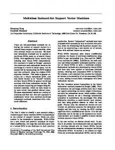
examining the shapes and spectral variation of their spectra, which is characteristic of their chemical compositions. 1.2 Hyperspectral imaging Conventional colour imaging sensors (“RGB” sensors) are able to capture the three primary colours perceived by human eyes. They operate by interlacing photodetectors sensitive to the red, green and blue regions of the spectrum on the same sensor array. In contrast with trichromatic sensors, multi-spectral and hyper-spectral imagers store colour information in a higher number of channels, each of which measures the amount of energy emitted within a specific band of wavelengths. The number of bands and the spectral density in such an image are determined by the hardware capability of the imaging sensor. In multi-spectral images, the number of bands is in the order of tens, whereas in hyperspectral images, there are hundreds or thousands of very narrow bands. Commonly, hyperspectral images are captured and digitised in a discrete form known as a three dimensional image cube, including two spatial dimensions and a spectral one. Fig. 1 illustrates this three-dimensional structure. As show on the left-hand side, a spectral image is indexed to the pixel location and the central wavelength of each band. In other words, a spectral image can be formalised as a function ℒ: ℝ3 ⟼ ℝ. The irradiance spectrum at an image pixel is the collection of image intensity (irradiance) values at that pixel across the entire wavelength range, as demonstrated on the right-hand side of the figure. The image intensity values captured by a camera, also known as irradiance values, are dependent on the illumination condition, the object shape and the surface material reflectance. The illumination at each surface location is determined by factors such as illumination intensity, illumination colour and shadow and is possibly spatially varying. The latter term, i.e., the surface material reflectance, is defined as the fraction of light from the illumination source that is reflected from a surface. This quantity is an objective measure of the underlying surface characteristics and is independent of the illumination condition. Due to this property, material reflectance has been employed as a robust feature for material classification. In hyperspectral imaging, the intrinsic colour of a material is captured by narrow-band spectral filters and resolved into a collection of values corresponding to various wavelengths in the spectrum. These wavelength-index values are referred to as the material reflectance spectrum or material spectral signature. Material spectral signatures have the advantage of being able to discern metamers, i.e., colours with different spectral power distribution but appear to correspond to similar trichromatic responses. Since material reflectance spectra are invariant to the illumination condition, it has attracted growing interests for applications in the areas of material classification and mapping in aerial imaging (Slater and Healey 1997, Healey and Slater 1999, Suen and Healey 2001) and terrestrial imaging (Angelopoulou 2000, Angelopoulou et al. 2001).
2. Case study: The Sydney Harbour Bridge The Sydney Harbour Bridge was opened to the public in 1932 and is one of the most iconic structures in Australia. It is the sixth longest spanning-arch bridge in the world and the tallest steel arch bridge, measuring 134 m from the water level to the top of the arch. The bridge plays a critical role in connecting the Sydney CBD with the Northern suburbs of Sydney. The total weight
184
Cong Phuoc Huynh, Samir Mustapha, Peter Runcie and Fatih Porikli
of the steelwork of the bridge, including the arch and approach spans, is 52,800 tonnes. The steel components are joined together by over six million rivets (NSW 2011a). Steel components on the Sydney Harbour Bridge introduces a very a significant challenge in terms of protection required to prevent corrosion. This is particularly true given the maritime location of the bridge. Over time the paint suffers degradation due to UV light and harsh weather conditions and must be replaced to ensure the steel is fully protected. There are approximately 272,000 litres of paint needed to paint the bridge (primer and final coat) (NSW 2011b). Therefore, ensuring a high quality protective coating to seal the steel is essential to prevent rusting from occurring. The inspection and replacement of paint is conducted as a regular task of bridge structure maintenance. Being able to accurately predict when repainting will be required would greatly aid maintenance planning and result in significant cost efficiencies particularly in the areas of site access and preparation. We collect data for the study from two locations on the eastern side of the Sydney Harbour Bridge. The first location was on the top of the lower arch were the short range images were captured. The second location was on the eastern side near the north pylon, in this location the mid-range images were captured (shown in Fig. 2). The main reason that those locations were chosen is the fact that they contain the four different levels of paint failures described below. Eventually any location on the bridge can be selected to capture the data. A four level rating system is commonly used for assessing civil structures in Australia – other countries and industries adopt similar systems but may have a different number of levels. The four rating levels used by bridge inspectors and in our study are as follows: ● Level 1: the protective coating is generally sound and unbroken. ● Level 2: the protective coating is exhibiting white or red rusting with minor speckles or localised pinhead rusting. ● Level 3: the protective coating is exhibiting speckled white rusting in areas greater than 2% and less than 5% of total surface area, or speckled red rusting in areas greater than 0:5% and less than 5% of total surface area. ● Level 4: the protective coating is no longer effective, with red and white speckled rust in areas larger than 5% of total surface area. Any given bridge component may have a mixture of different rating levels such as 70% Level 1, 20% Level 2 and 10% Level 3.
3. Data processing: algorithm development In this section, we present an image processing and classification procedure to arrive at an objective condition rating of steel surfaces. The classification of the acquired images is based on the four level rating system described above. We aim to design an automatic data-driven classifier based on exemplar surface areas belonging to each level as provided by human experts, e.g., bridge inspectors. Therefore we could avoid the need for handcrafting certain correlation criteria between rating levels and image features such as reflectance spectra. This strategy relieves some unnecessary manual work, while allowing for more generality of the resulting classifier. After collecting images on site, the data were processed in two phases, as illustrated in Fig. 3. In the training phase, a number of images were randomly selected for training and several image
Multi-class support vector machines for paint condition assessment…
185
regions are labelled with the respective rating levels.
Fig. 1 Left panel: a hyperspectral image is visualised as a data cube with three dimensions spanning both the spatial and spectral domains. Right panel: Intensity values at the same image pixel form the irradiance spectrum at that pixel
Fig. 2 Data capturing - Location 1: on the top of the lower arch and Location 2: near the bottom of the north pylon (Australia 2010)
Subsequently, the spectral reflectance spectra were extracted, which is invariant to the illumination condition, from the training regions. Taking these reflectance spectra as input, a Support Vector Machines (SVM) (Cristianini and Shawe-Taylor 2000) was trained in order to perform automatic classification of surface condition ratings. This process is depicted in Fig. 3(a). In the classification phase, reflectance spectra were first extracted from the image of a novel surface and treated as input to the classifier learned previously. At this point, the classifier assigns
186
Cong Phuoc Huynh, Samir Mustapha, Peter Runcie and Fatih Porikli
a surface rating label to each pixel based on its reflectance spectrum. The aggregation of all the labels in an image yields the proportion of the surface area belonging to each rating category. The classification phase is illustrated in Fig. 3(b). 3.1 Image region labelling For the labelling task, a number of images were selected randomly as training data and subsequently were provided to a human expert, e.g., a bridge inspector. To minimise mislabelling, the human expert was present at the collection site to make an observation of the actual surface being imaged. The labelling was performed shortly after the acquisition of each training image. At this point, the human expert selected pixel regions and assigned a label corresponding to their condition ratings, according to his observation of the actual surface. To facilitate this task, we have developed a graphical user interface for managing training images and rating labels as shown in Fig. 4 (This tool is part of the NICTA's Scyllarus hyperspectral image processing pipeline. See http://scyllarus.research.nicta.com.au). Using this tool, a human expert is able to select multiple polygonal regions in an image and provide a label for each of them. The “Polygon Labels” panel at the top right corner displays various region labels for each image and allows the selection and de-selection of region groups sharing the same label, by switching on and off the respective label item. The bottom-right panel presents the set of all training images to the user.
(a)
(b) Fig. 3 The process of hyperspectral image analysis for surface condition rating. Top: The (off-line) training phase consists of the labelling of image regions with surface condition ratings by human experts, the extraction of material reflectance features from the labelled image regions and the supervised training of a classifier. Bottom: in the (online) classification process, material spectral signatures are extracted from a novel image and passed to the learned classifier as features for classification
Multi-class support vector machines for paint condition assessment…
187
3.2 Extracting material reflectance In this section, we describe a method for extracting reflectance spectra from a given hyper-spectral image. As mentioned earlier, reflectance is a material intrinsic property that is invariant to the illumination variation. Therefore, we choose to employ reflectance as a robust feature for the classification of surface condition ratings. To this end, we depart from an image formation model that decomposes a hyper-spectral image into the illumination power spectrum and the underlying surface material reflectance. Here, we assume that the scene is uniformly illuminated by a single light source and the irradiance arriving at the camera sensor is proportional to the scene radiance. We denote the radiance reflected from a scene location 𝑢 and a wavelength 𝜆 as 𝐼(𝑢, 𝜆). In addition, 𝐿(𝜆) denotes the (spatially uniform) illumination power spectrum and 𝑆(𝑢, 𝜆) is the surface reflectance function at the above location and wavelength. The relationship between the scene radiance and the latter two terms is well-understood by numerous works in colour constancy (Land and McCann 1971), (Land 1986) and illumination recovery (Kimmel et al. 2003), and is mathematically expressed as follows 𝐼(𝑢, 𝜆) = 𝐿(𝜆)𝑆(𝑢, 𝜆)
(1)
The matter of separating the material reflectance from the illumination power spectrum given the irradiance image is closely related to the large body of works in computational colour constancy. This area of research aims to resolve the intrinsic material colour from images captured under varying illumination conditions. To this end, we leverage a simple and widely adopted approach known as the Grey-World method (Buchsbaum 1980). This method relies on the hypothesis that the spatial average of surface reflectances in a scene is achromatic, i.e., the illuminant spectrum can be estimated by taking the average of the sensor responses in the image. It is a member of a wider family of color constancy methods directly applicable to single images with no requirements for pre-processing or prior knowledge gathered from training data. Other popular methods in this group include the White-Patch approach (McCann et al. 1977), the Shade-of-Gray method (Finlayson and Trezzi 2004), and the Grey-Edge method (Van de Weijer et al. 2007). Using the Grey-World method, the illumination power spectrum is estimated as ̂𝐿(𝜆) = 〈𝐼(𝑢, 𝜆)〉𝑢
(2)
where 〈⋅ 〉𝑢 is an abbreviation for the average of the argument over all the pixel locations. With this estimate of the illumination power spectrum, the spectral reflectance can be computed as 𝑆(𝑢, 𝜆) =
𝐼(𝑢,𝜆) 𝐿̂ (𝜆)
(3)
3.3 Training a classifier In the previous section, we have obtained a reflectance spectrum 𝑆𝑢 ≜ ,𝑆(𝑢, 𝜆1 ), 𝑆(𝑢, 𝜆2 ) … 𝑆(𝑢, 𝜆𝑁 )- per pixel 𝑢 assuming that the input hyper-spectral images are sampled at 𝑁 wavelengths 𝜆𝑖 , 𝑗 = 1, 2, … 𝑁. At the training phase, we take input from these reflectance spectra and their associated labels, which have been provided by the human expert. Here, we denote the label associated with the spectrum 𝑆𝑢 as 𝑦𝑢 , where 𝑦𝑢 ∈ *1, … , 𝐾 + and 𝐾 is the number of condition rating levels. At
188
Cong Phuoc Huynh, Samir Mustapha, Peter Runcie and Fatih Porikli
this point, we tackle this multi-class classification problem by adopting the “one-against-one” approach in which we perform binary classification for every pair of classes. In other words, the approach constructs 𝐾(𝐾 − 1)/2 binary classifiers in total. For a pair of 𝑝-th and 𝑞-th classes, the optimal Support Vector Machines (SVM) binary classifier (Cristianini and Shawe-Taylor 2000) is represented as a separating hyperplane that maximises the margin between samples in the two classes. Formally, we find this classifier by solving the following problem. min
𝑤 𝑝𝑞 ,𝑏 𝑝𝑞 ,𝜉 𝑝𝑞
1 𝑝𝑞 2 ‖𝑤 ‖ + 𝐶 ∑ 𝜉𝑢𝑝𝑞 2 𝑢
subject to and
(𝑤 𝑝𝑞 )𝑇 ϕ (S𝑢 ) + 𝑏 𝑝𝑞 ≥ 1 − 𝜉 𝑝𝑞 , if y𝑢 = p (𝑤 𝑝𝑞 )𝑇 ϕ (S𝑢 ) + 𝑏 𝑝𝑞 ≥ −1 + 𝜉 𝑝𝑞 , if y𝑢 = q,
(4)
where 𝑤 𝑝𝑞 is the normal vector of the separating hyperplane between the classes, ‖ ⋅ ‖denotes the 𝑝𝑞 𝐿2 -norm of a vector, 𝑏 𝑝𝑞 is an offset from the origin, 𝜉𝑢 is a non-negative slack variable for each pixel 𝑢 and 𝜉 𝑝𝑞 is a vector formed by concatenating the slack variables over all the training pixels in the mentioned classes. In the case where the classes are non-separable, the slack variables accounts for margin 𝑝𝑞 violations caused by training samples. The total error due to margin violations, i.e., ∑𝑢 𝜉𝑢 , is weighted by a factor 𝐶. In the formulation above, we note that the function 𝜙 ∶ ℝ𝑁 ⟼ ℋ maps the reflectance spectra 𝑆𝑢 ∈ 𝑅𝑁 to a high-dimensional space ℋ, in which the training samples of the 𝑝-th and 𝑞-th classes are separable. The above problem is convex and can be reformulated in the dual form as follows (Boyd and Vandenberghe 2004) 1 𝑝𝑞 𝑇 (𝛼 ) 𝑄(𝛼 𝑝𝑞 ) − 𝑒 𝑇 𝛼 𝑝𝑞 2 subject to (𝑦 𝑝𝑞 )𝑇 𝛼 𝑝𝑞 = 0, 𝑝𝑞 0 ≤ 𝛼𝑢 ≤ 𝐶, min 𝛼𝑝𝑞
for pixel 𝑢 in the 𝑝-th and 𝑞-th classes where 𝑒 is the vector of all ones.
Fig. 4 The graphical user interface for labelling image regions with condition ratings
(5)
Multi-class support vector machines for paint condition assessment…
189
In the dual form, we aim to solve for the dual variable 𝛼 whose element 𝛼 𝑝𝑞 is indexed to a 𝑝𝑞 training pixel 𝑢 in the 𝑝-th and 𝑞-th classes. Here, 𝑦𝑢 is a vector indexed to the training pixel, 𝑝𝑞 𝑝𝑞 where 𝑦𝑢 = 1 if 𝑦𝑢 = 𝑝 and 𝑦𝑢 = −1 if 𝑦𝑢 = 𝑞 . We also denote the kernel function 𝐺 ∶ ℝ𝑁 × ℝ𝑁 ⟼ ℝ for each pair of pixels 𝑢 and 𝑣 as 𝐺(𝑢, 𝑣) = 𝜙(𝑢)𝑇 𝜙(𝑣). In addition, Q is an 𝑀 × 𝑀 matrix with rows and columns indexed to the training pixels in the 𝑝 − 𝑡ℎ and 𝑞 − 𝑡ℎ classes and 𝑀 is the number of training samples in both classes. Each element of Q is 𝑝𝑞 𝑝𝑞 𝑝𝑞 𝑝𝑞 related to the kernel function by 𝑄𝑢,𝑣 = 𝑦𝑢 𝑦𝑣 𝐺(𝑢, 𝑣) = 𝑦𝑢 𝑦𝑣 𝜙(𝑢)𝑇 𝜙(𝑣). In our experiment, we employ a linear kernel for the SVM classifier. To solve the problem in Eq. (5), we employ the Sequential Minimal Optimization (SMO) approach (Platt 1999) implemented by the LibSVM software library (Chang and Lin 2011). The SMO technique is an iterative one, modifying a subset of dual variables in each iteration. By exploiting the fact that the original problem in Eq. (5) can be decomposed into small sub-problems, the SMO approach is able to deal with its scale efficiently. 3.4 Classification of surface conditions The above section describes the process of training binary classifiers to distinguish every pairs of condition ratings. Given the classifier for the 𝑝 -th and 𝑞 -th condition ratings, the binary classification of a test reflectance spectrum 𝑆𝑥 is determined by the following decision function 𝑝𝑞 𝑝𝑞
𝑠𝑔𝑛(∑ 𝑦𝑢 𝑦𝑣 𝐺(𝑢, 𝑥)),
(6)
where the 𝑠𝑔𝑛(⋅) denotes the sign function. In order to perform multi-class classification, we adopt a voting strategy, where each binary classifier contributes a vote on the condition rating (class) of the test spectrum 𝑆𝑥 . In the end, the votes of all the classifiers are aggregated and the input sample is assigned a condition rating with the maximum number of votes.
4. Experimental results In this section, we aim to validate the consistency of the classification performance across two acquisition ranges and two lighting conditions. 4.1 Image dataset To validate our classification approach, we chose to examine two locations on the bridge, one at the top of the lower arch on the western side and the other at the north pylon on the eastern side. At each location, we collected a set of 14 images of surfaces exhibiting various degrees of corrosion, corresponding to the four rating levels described in Section 2. We aim to analyse the variation of classification results with respect to the acquisition distance, i.e., the distance from the camera and the surface to be imaged. For this purpose, the imaging conditions at these two locations differ in the range of acquisition distance and the acquisition time. Specifically, the distance was less than 5 metres at the former location and between 10 and 40 metres at the latter one. Hence, for convenience, we name these two data sets as the short-range
190
Cong Phuoc Huynh, Samir Mustapha, Peter Runcie and Fatih Porikli
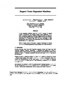
and mid-range image sets. In addition, we deliberately chose different acquisition times for the two sets, with the first one acquired in the morning and the latter one in the afternoon. This choice serves the purpose of validating the robustness of our data processing approach to the illumination variation throughout the day. The acquisition apparatus consists of a hyper-spectral camera equipped with an Acousto-Optics Tunable Filter (AOTF). The filter selects wavelengths using a quartz crystal attached to a transducer. When a radio frequency (RF) acoustic wave is applied to the transducer, it causes the compression and relaxation of an optically anisotropic crystal (Denes et al. 1998, Gupta et al. 2002). As a consequence, this mechanism tunes the refractive index of the crystal, creates diffraction and separates the broad spectrum of incident light into different bands of wavelengths. For the experiments, we opt for the wavelength range of 450-650nm with a 10 nm incremental step between successive bands. During our experiments, we found that this choice of sample wavelengths yields a sufficient number of bands, i.e., 21, to capture and distinguish the characteristic spectra of the four surface level ratings in this study. This number of bands also offers a good trade-off between classification accuracy and speed of computation. In Fig. 5, we show the typical transmission of the AOTF spectral filters we employed for data acquisition. We note that the filter response peaks in the middle of the wavelength range and diminishes significantly at both the low and high ends 4.2 Classification results Having collected data for our study, we aim to verify the consistency of classification performance across the short-range and mid-range distances and the illumination variation throughout the day. For this purpose, we first train a classifier with a (training) subset from each of the short-range and mid-range dataset, and subsequently classify the remaining images (i.e., the test set) with the constructed classifier.
Fig. 5 Optical transmission of an acousto-optic tunable filter (AOTF), depicted as a function of the wavelength
Multi-class support vector machines for paint condition assessment…
191
To obtain training data, we randomly selected four images from each of the short-range and mid-range image sets. As described in Section 3.2, reflectance spectra were extracted from the selected images and normalised to unit power. We then form the training data from the reflectance spectra of the labelled regions in the selected images. It is worth mentioning that, so far, the training data only concerns the example surfaces with one of the rating levels in our study. However, the data has not included examples of surfaces not falling into any of these categories. To gather prior knowledge of these unseen categories, we have added training data for a “background” class by randomly selecting image regions that correspond to sky areas, shadows etc. With this additional class, the background regions would be distinguished from those with the rating levels of interest. Therefore, the data in these regions would not interfere with the surface condition rating results. In Fig. 6, we present the training reflectance spectra from the mid-range images for the four rating levels in consideration. Here, we note that the mean reflectance spectrum for each rating level exhibits a distinct trend of spectral variation. Furthermore, when comparing two set of spectra belonging to each pair of rating levels (except level 3 and 4), we notice a significant difference in the reflectance value over a number of bands, i.e., the difference between the means is above one standard deviation of each set. This observation hints at the use of reflectance spectra for classifying surfaces into condition rating levels.
(a) Level 1
(b) Level 2
(c) Level 3
(c) Level 4
Fig. 6 Means and standard deviations of the training reflectance spectra belonging to surface rating levels between 1 and 4
192
Cong Phuoc Huynh, Samir Mustapha, Peter Runcie and Fatih Porikli
Table 1 Classification of pixels in the short-range images into rating levels. We report the percentage of pixels classified into the given classes and the overall classification rate Classified
Level 1
Level 2
Level 3
Level 4
Background
Level 1
57.87
32.78
0.15
0.71
8.48
Level 2
-
-
-
-
-
Level 3
0.07
31.1
0.68
68.14
0.005
Level 4
0.05
9.98
2.14
76.72
12.10
Background
3.43
1.72
1.47
0.86
92.52
Actual
Overall
75.19
Table 2 Classification of pixels in the mid-range images into rating levels. We report the percentage of pixels classified into the given classes and the overall classification rate Classified
Level 1
Level 2
Level 3
Level 4
Level 1
90.37
Level 2
Background
5.82
3.72
0.06
0.02
6.75
84.40
1.14
5.41
2.30
Level 3
16.77
9.21
49.66
24.33
0.01
Level 4
0.02
0.66
41.99
57.11
0.22
Background
5.42
1.41
0.04
1.80
91.32
Actual
Overall
85.54
With the above training data, we trained a soft-margin Support Vector Machines (SVM) classifier with a linear kernel. As shown in Eq. (4), this classifier is parameterised by the weight 𝐶 of the slack 𝑝𝑞 variables 𝜉𝑢 . We searched for the optimal 𝐶 value within the range of [1; 100] by a five-fold cross validation procedure. After training the SVM classifier with this optimal parameter value, we employed it to classify the reflectance spectrum at every pixel in novel test images. In our experiments, we selected four mid-range images and employed data from their labelled regions as input for training an SVM classifier. To quantify the accuracy of this classifier, we compare the predicted rating levels in the remaining images with the ground truth given by the human expert, at image regions where the expert labels are available. We then report the classification accuracy with respect to the ground truth labels in terms of the confusion matrix between the rating levels. In Tables 1 and 2, we report the classification accuracy for each class and the overall classification rate for both the short-range and mid-range images. The diagonal elements show the percentages of pixels correctly classified for each class, whereas the off-diagonal ones show the percentages of pixels misclassified into a class other than the ground truth one. Here, the rows correspond to the ground truth labels and the columns correspond to the predicted labels, respectively. We note that, since no pixels were labelled with a rating level of 2 in the short-range
Multi-class support vector machines for paint condition assessment…
193
dataset, the classification rate for rating level 2 is not reported in Table 1. For both the image sets, the background class is segmented with a high level of accuracy. In addition, the pixels of level 1 in the mid-range image set are recognised reasonably well. However, a significant proportion (32.78%) of level-1 pixels in the short-range images is misclassified as belonging to level 2. Furthermore, it is consistently observed that there is a high level of confusion between levels 3 and 4 in both image sets. This confusion can be explained by the fact that the training reflectance spectra for these two levels exhibit similar variations across wavelengths, as shown in Figure 6. This suggests that more training data is needed for the fine-grained classification between intact coating and minor rust, and between the two most severe levels of corrosion. Despite this confusion, the classifier is able to achieve reasonable overall classification rates of 75.19% and 85.54% for the short-range and mid-range images, respectively. Next, we visually examine the surface rating maps that results from the pixel-wise classification performed on novel images. Figs. 7 and 8 depict the rating maps for several sample short-range and mid-range images, respectively. The top rows of these figures show the input images rendered in pseudo-colour, whereas the bottom rows show the segmentation of these images into rating levels coded in distinct colours. The colour bar at the bottom displays the colour codes of the given rating levels along a scale between 1 and 5. Here, level 5 is an artificial label reserved for the “background” class, which is displayed in red.
Fig. 7 Surface rating maps of sample short-range images, resulting from the pixel-wise classification using an SVM classifier that we trained on a number of mid-range images. Top row: input spectral images rendered in pseudo-colour. Bottom row: surface rating maps of the above images, shown in colours corresponding to the rating levels as indicated by the colour bar. The “background” is shown in red, with a pseudo rating level of 5
194
Cong Phuoc Huynh, Samir Mustapha, Peter Runcie and Fatih Porikli
Fig. 8 Surface rating maps of sample mid-range images, resulting from the pixel-wise classification using an SVM classifier that we trained on other mid-range images. Top row: input spectral images rendered in pseudo-colour. Bottom row: surface rating maps of the above images, shown in colours corresponding to the rating levels as indicated by the colour bar. The “background” is shown in red, with a pseudo rating level of 5
We also ensure the robustness of classification performance to the variation of the viewing angle to the surface normal. This robustness is achieved as a result of normalising the reflectance spectra to a unit norm in the feature extraction step in Fig. 3. Therefore, the reflectance spectra in such a case as in the top-left panel in Fig. 8, are invariant to the viewing angle, yielding consistent features for both the learning and classification steps. The overall observation is that the classifier excels at distinguishing regions with intact coating (level 1) from those with corrosion (levels 3 or 4). In addition, the background class is well-segmented from the images in both the short-range and mid-range categories. However, the classifier appears to be confounded by surface areas with similar ratings, such as levels 1 and 2, and levels 3 and 4. These qualitative observations are consistent with the classification accuracy reported earlier. This suggests that additional cues are needed to assist the successful discrimination of these rating levels. To improve classification performance, our classification framework could be extended to include spatial features of a region, such as textures and gradients, in addition to spectral reflectance.
Multi-class support vector machines for paint condition assessment…
195
5. Conclusions In this study, we have explored the effectiveness of hyperspectral imaging in the assessment of paint conditions on the ionic Sydney Harbour Bridge. A multi-class Support Vector Machines classifier was developed for this purpose. We have investigated the classification performance on short-range and mid-range images captured on two different locations on the bridge, based on that the following conclusions were drawn:
● For both short-range and mid-range images, the “background” class, which consists of areas not falling into the four rating levels in our study, was segmented from the other classes with a high level of accuracy (more than 90%). ● The classification of level-1 and level-2 regions in mid-range images is also effective (with nearly 85% or more), given the use of training data from the same range. ● There is still some degree of confusion between level 1 and 2, and level 3 and 4. ● Despite this confusion, the overall classification rates are promising (over 75%). The overall classification accuracy using the developed classifier has demonstrated a potential application of hyper-spectral imaging to paint condition assessment. In future works, we would consider the inclusion of discriminative training data for the fined-grained classification between level 1/level 2 and between level 3/level 4. To enhance the classification accuracy, a possibility is to combine spatial features, such as texture or image gradients, with the existing spectral reflectance feature. To enhance the robustness of the above approach, we would investigate a technique of normalising reflectance spectra across different light conditions, such as shadow removal. We also envisage an extension of the technique and results described above for paint condition assessment of the entire bridge. The framework would involve mapping hyperspectral images onto a 3D model of the bridge with the location information of each image. This additional information can be obtained in a straightforward manner by incorporating GPS trackers into the image acquisition process. A further step is to fuse information from multiple overlapping images by stitching them into panoramas. Image stitching method has been well-research and developed into mature software such as the Microsoft Image Composite Editor (ICE) (for more information, see http://research.microsoft.com/en-us/um/redmond/projects/ice/). In this study, we have only acquired images from human-accessible locations with a portable camera system. For a comprehensive assessment of the bridge, it is necessary to develop a method for acquiring images from various viewpoints and distances. To perform acquire images of inaccessible areas, we would resort to an image system mounted on a climbing robot or an unmanned aerial vehicle (UAV) with additional telephoto lenses for far range imaging. This additional data would open up opportunities for remote inspection of surface areas not easily accessible.
Acknowledgments The authors would like to thank the New South Wales Department of Road and Maritime Services (RMS) for their assistance and access to Sydney Harbour Bridge during the data acquisition for this study. They also appreciate the work by Nariman Habili and Jeremy Oorloff,
196
Cong Phuoc Huynh, Samir Mustapha, Peter Runcie and Fatih Porikli
which enables the data labelling process through the Scyven software. NICTA is funded by the Australian Government as represented by the Department of Broadband, Communications and the Digital Economy and the Australian Research Council through the ICT Centre of Excellence program.
References Angelopoulou, E. (2000), “Objective colour from multispectral imaging”, European Conference on Computer Vision. Angelopoulou, E., Molana, R. and Daniilidis, K. (2001), “Multispectral Skin Color Modeling”, Computer Vision and Pattern Recognition, 2, 635-642. ASTM-D610–08 (2012), Standard Practice for Evaluating Degree of Rusting on Painted Steel Surfaces, ASTM International, West Conshohocken, PA. ASTM-D662-93 (2011), Standard Test Method for Evaluating Degree of Erosion of Exterior Paints, ASTM International, West Conshohocken, PA. ASTM-D5065-13 (2013), Standard Guide for Assessing the Condition of Aged Coatings on Steel Surfaces, ASTM International, West Conshohocken, PA. Australia, E.S. (2010), “Sydney Harbour Bridge”, Retrieved 9th of January, 2015, from http://www.experiencesydneyaustralia.com/sydney-australia-highlights/sydney-harbour-bridge/. Bayer, G.T. and Zamanzadeh, M. (2004), “Failure analysis of paints and coatings”, published internally by Matco Associates, 331. Boyd, S. and Vandenberghe, L. (2004), Convex Optimization, Cambridge University Press. Buchsbaum, G. (1980), “A spatial processor model for object colour perception”, J. Franklin Inst., 310(1), 1-26. Chang, C.C. and Lin, C.J. (2011), “LIBSVM: A library for support vector machines”, ACM T.Intell. Syst. Technol., 2(3), 21-27:27. Cristianini, N. and Shawe-Taylor, J. (2000), An Introduction to Support Vector Machines: And Other Kernel-based Learning Methods, Cambridge University Press, New York, NY, USA. Denes, L.J., Gottlieb, M.S. and Kaminsky, B. (1998), “Acousto-optic tunable filters in imaging applications”, Opt. Eng., 37(4), 1262-1267. Dundar, M. and Landgrebe, D. (2004), “Toward an optimal supervised classifier for the analysis of hyperspectral data”, IEEE T. Geosci. Remote, 42(1), 271-277. Finlayson, G.D. and Trezzi, E. (2004), “Shades of gray and colour constancy”, Color Imaging Conference, Society for Imaging Science and Technology. Gerlock, J.L., Smith, C.A., Cooper, V.A., Dusbiber, T.G. and Weber, W.H. (1998), “On the use of Fourier transform infrared spectroscopy and ultraviolet spectroscopy to assess the weathering performance of isolated clearcoats from different chemical families”, Polym. Degrad. Stabil., 62(2), 225-234. Goetz, A.F.H. (2009), “Three decades of hyperspectral remote sensing of the Earth: A personal view”, Remote Sens. Environ., 113(1), 5-16. Gupta, N., Dahmani, R. and Choy, S. (2002), “Acousto-optic tunable filter based visible to near-infrared spectropolarimetric imager”, Opt. Eng., 41(5), 1033-1038. Healey, G. and Slater, D. (1999), “Invariant recognition in hyperspectral images”, IEEE Conf. on Computer Vision and Pattern Recognition, 1438-1043. Huynh, C.P. and Robles-Kelly, A. (2010), “Hyperspectral imaging for skin recognition and biometrics”, IEEE International Conference on Image Processing (ICIP), 2325-2328. Kimmel, R., Elad, M., Shaked, D., Keshet, R. and Sobel, I. (2003), “A variational framework for retinex”, Int. J. Comput. Vision., 52(1), 7-23. Land, E.H. (1986), “Recent advances in Retinex theory”, Vision Res., 26(1), 7-21.
Multi-class support vector machines for paint condition assessment…
197
Land, E.H. and McCann, J.J. (1971), “Lightness and retinex theory”, J. Opt. Soc. Am., 61(1), 1-11. McCann, J.J., Hall, J.A. and Land, E.H. (1977), “Color Mondrian experiments: the study of average spectral distributions”, J. Opt. Soc. Am., 67, 1380. NSW, G. (2011a), “Sydney Harbour Bridge: Rivets”, Retrieved 9th of January, 2015, from http://sydney-harbour-bridge.bos.nsw.edu.au/engineering-studies/rivets.php. NSW, G. (2011), “Sydney Harbour Bridge: Corrosion”, Retrieved 9th of January, 2015, from http://sydney-harbour-bridge.bos.nsw.edu.au/engineering-studies/corrosion.php. Platt, J.C. (1999), Fast Training of Suport Vector Machines using Sequential Minimal Optimization, Advances in Kernel Methods: Support Vector Learning, Christopher J.C. Burges and A.J. Smola, Cambridge, MA, USA, MIT Press: 185-208. Poliskie, M. and Clevenger, J.O. (2008), “Fourier transform infrared (FTIR) spectroscopy for coating characterization and failure analysis”, Metal Finishing, 106(5), 44-47. Slater, D. and Healey, G. (1997), “Object recognition using invariant profiles”, Proceedings of the Computer Vision and Pattern Recognition, IEEE. Suen, P.H. and Healey, G. (2001), “Invariant mixture recognition in hyperspectral images”, Int. Conference on Computer Vision, IEEE. Tiong, U. and Clark, G. (2011), Aircraft Joints and Corrosion Control, ICAF 2011 Structural Integrity: Influence of Efficiency and Green Imperatives, J. Komorowski, Springer Netherlands, 625-634. Van de Weijer, J., Gevers, T. and Gijsenij, A. (2007), “Edge-based color constancy”, IEEE T. Image Process., 16(9), 2207-2214. Wyszecki, G. and Stiles, W. (2000), Color Science: Concepts and Methods, Quantitative Data and Formulae. Wiley.